What the iMeshh Roof Generator is and why it exists
An overview of the months-long roof generator release: what's included with the iMeshh subscription, where to report bugs, and how this version-one tool fits into the asset manager workflow.
Intro, credits and where to get the generator
Welcome to the iMeshh Roof Generator walkthrough. If you've already downloaded the generator and you're staring at a fresh roof object wondering which attribute does what, this post is the how-to guide that takes you from import to a finished, photoreal roof: tiles, ridges, gutters and all.

The generator is months of work, and it wouldn't exist without Kate White, who collaborated with iMeshh on the build. Full credit and a link to her socials live in the Tools, assets and credits section at the bottom of this post.
This is version one. We've squashed every bug we could reproduce, but roofs come in an infinite variety of shapes and edge cases, so if you hit something that misbehaves please let us know on Discord and we'll push a fix to everyone. If you're an iMeshh subscriber using the asset manager, you'll be notified automatically whenever a new version drops, and new features are being added on a rolling basis.

With the housekeeping out of the way, the rest of this post walks through the generator end-to-end: how the attribute system works, how to build and randomise a tile collection, how to wire up ridges, hips, valleys, fascia and soffits, how to add gutters that snap into place, and how to finish the roof with moss, snow guards and even a fully procedural metal panel build.
Attributes 101: the foundation of every roof control
Before touching any roof parameter, you need to understand how Blender mesh attributes drive the generator. This module shows how to assign edge and face attributes, set them with F3, and use them in place of any sliderable value.
Show emitter and selecting faces on the plane
Right at the top of the generator's panel sits the Show Emitter toggle. Switch it on, drop into edit mode and you'll see the bare plane underneath the finished roof. That's the surface the whole generator is built from. Turn the toggle back off and the helper geometry hides again, leaving just the generated roof on screen.
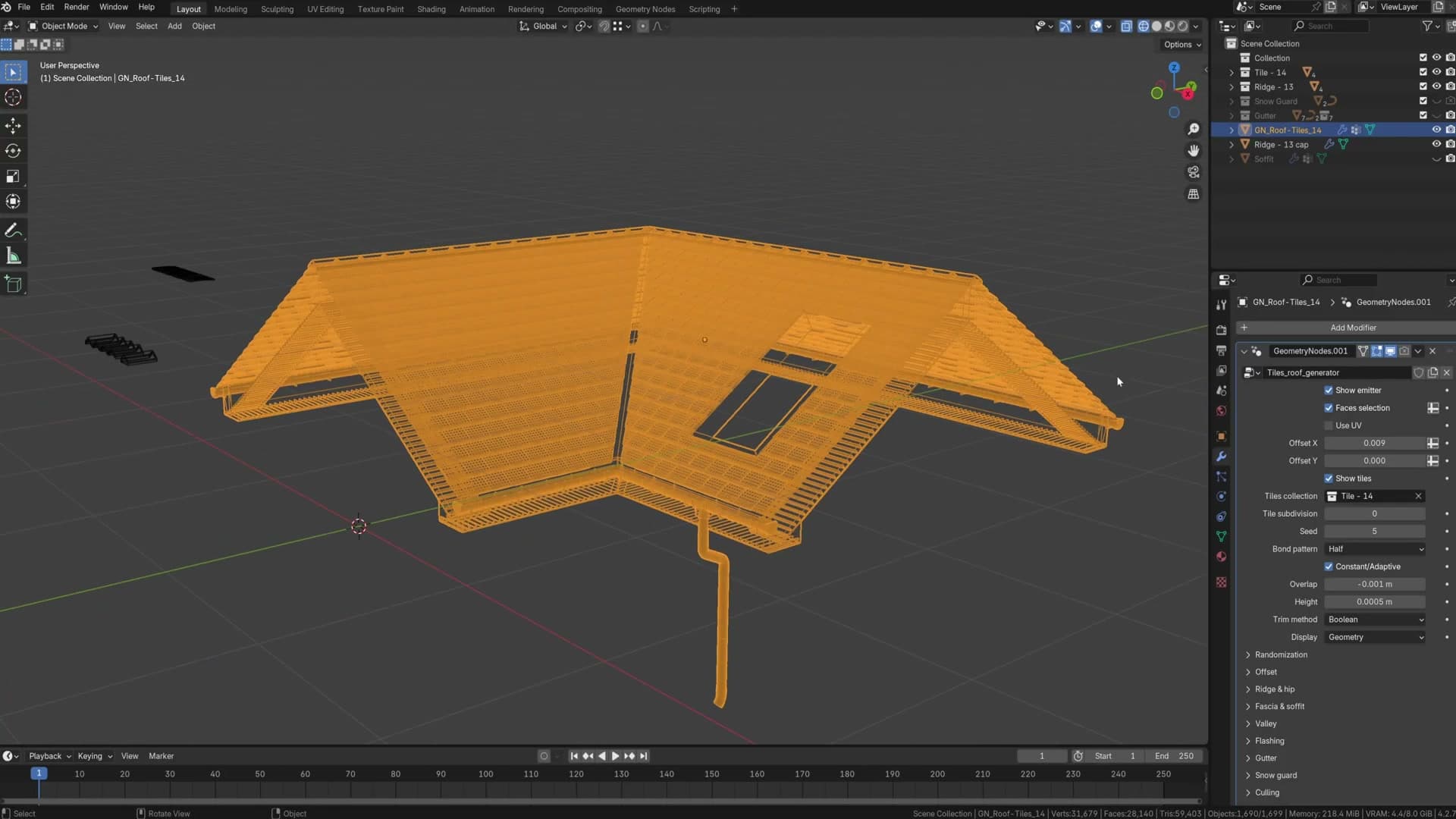
Next to Show Emitter is Face Selection, and that's your first clue about how the generator wants you to interact with it. Anywhere you spot one of these small attribute icons beside a parameter, the parameter can be driven by a mesh attribute instead of a single global value.
It's worth getting comfortable with that idea before going any further: almost every meaningful control on this generator funnels through attributes, so the upfront time you spend on this module pays back across every section that follows.
Attributes work like vertex groups
If you've ever used a vertex group, attributes will feel familiar. In Object Data Properties, scroll down to the Attributes panel. It sits in the same neighbourhood as the vertex group list, and the assign/select workflow is essentially identical.
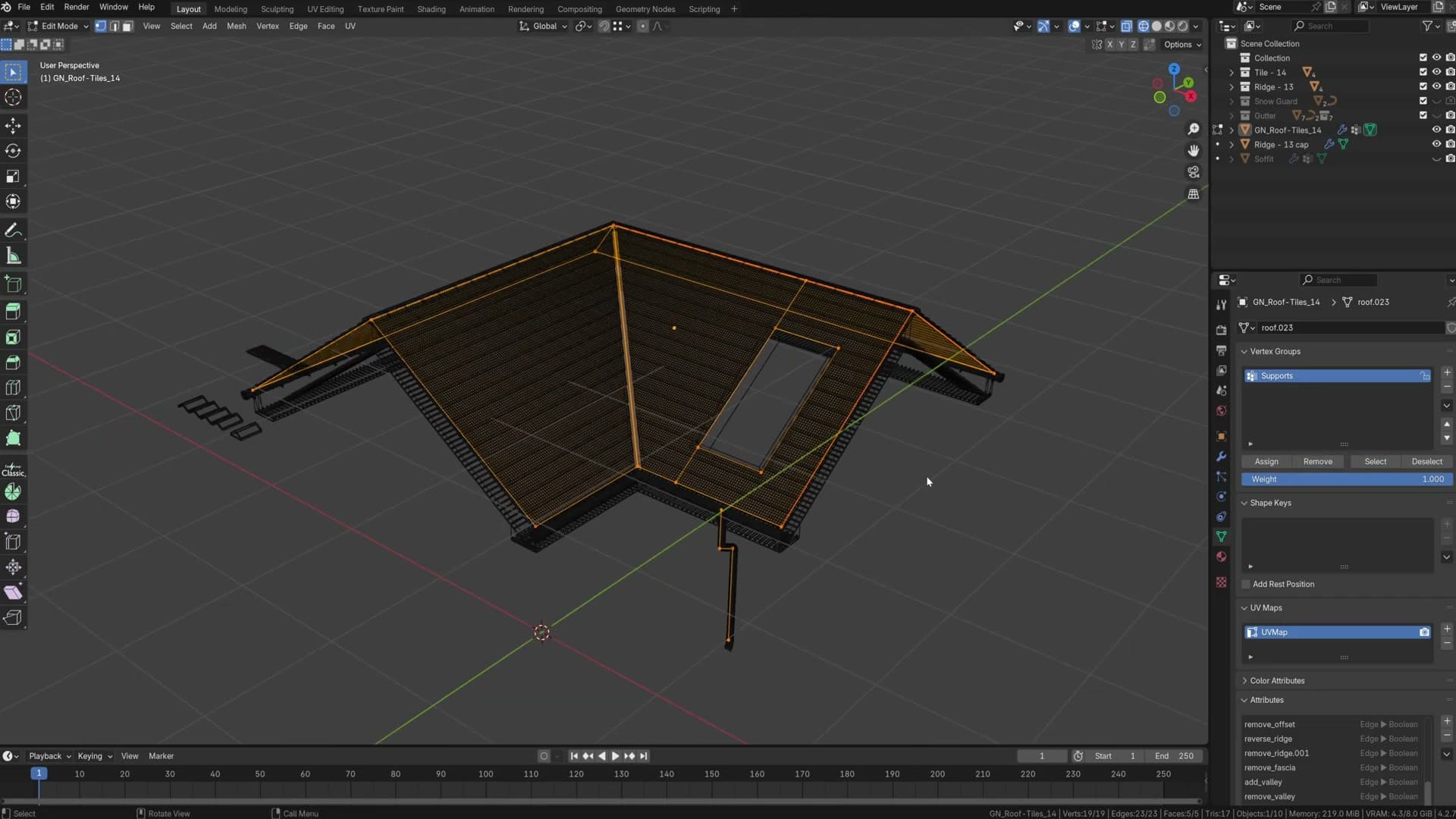
With a vertex group you'd select a vertex, click Assign to add it to the group, and click Select to confirm which vertices belong. Attributes follow the same pattern: pick the geometry you want, write it into an attribute, and that attribute now carries a flag the generator can read.
The mental shift is that each attribute drives one parameter. Where a slider gives every face or edge the same value, an attribute lets you flip a property on or off (or vary its value) per face, per edge, or per vertex on the emitter.
Assigning an edge attribute (add gutter example)
The cleanest way to see this in action is the gutter. Switch to edge select mode and pick the edge where you want a gutter to run along the roof.
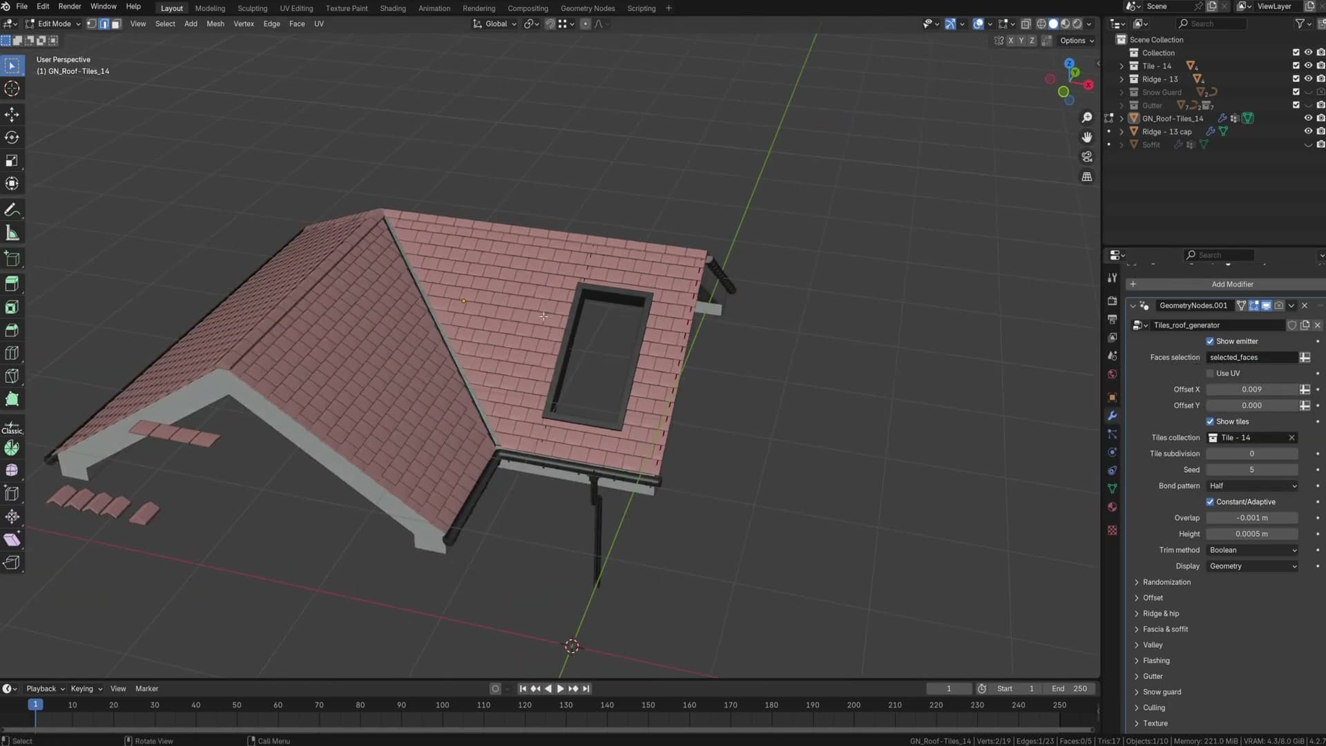
In the Roof Generator panel, find the Add Gutter parameter and click the attribute toggle button next to it (the icon flagged in the previous step). With the edge still selected, click Set Attribute and choose add_gutter. The gutter immediately appears along that edge.
The same three-step pattern works for any parameter that shows the attribute icon: select the geometry first, click the parameter's toggle button, then click Set Attribute and pick the matching attribute name.
Creating a custom attribute for per-face offset
Not every parameter ships with its own pre-named attribute. When you want to drive something like Offset Y on a per-face basis, you create your own attribute on the emitter and type its name into the parameter's field on the generator.
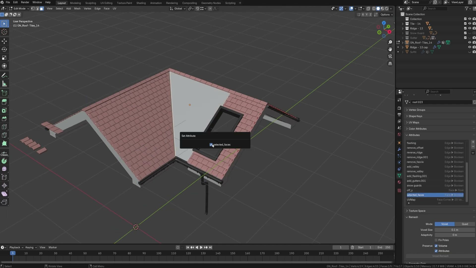
Press 3 to drop into face select, then click the faces you want this offset to apply to. Head down to the Attributes list in Object Data Properties and add a new one. The video uses off Y as a short stand-in for the Y offset, but the name itself is arbitrary as long as it matches what you type into the parameter.
With your faces still selected, press F3, search for Set Attribute, and run it. That writes your selection into the attribute you just made. Type the same name into the Offset Y field on the generator and the parameter starts respecting your per-face mask instead of applying globally.
Tile collection, origin points and UV offsets
How the roof generator picks tiles from a collection, why the origin point determines overlap and scale behaviour, and when to switch from X/Y offsets to per-face UV island manipulation.
Offset X and Offset Y tile shifting
Once tiles are showing, the two quickest controls you have are Offset X and Offset Y. Drag either slider and the whole tile field shifts along that axis. It always snaps in increments of the tile width, so the courses stay aligned and you never end up with half a tile dangling off the edge.
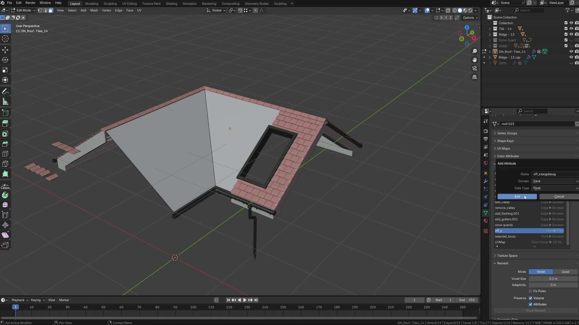
Both offsets can be driven by an attribute, which is how you get a different shift on each face of the roof. In edit mode, select the face you want to vary, press F3, search for Set Attribute, type the attribute name (for example off Y or off X) and run it. Back on the generator, point the offset property at that same attribute name and your per-face value takes over.
If nothing changes when you first do this, it's almost always because the attribute doesn't exist yet on the face you're editing. Open the Attributes panel, add it manually as a Face attribute, then run Set Attribute again. From there you can shift any individual face independently, which gives you per-face customisability across the entire roof system.
For most roofs you won't need any of this. The default X and Y offsets, with no attribute hooked up, are usually all you need to nudge the tile pattern into a sensible alignment.
Use UV mode for per-face rotation control
If the X/Y offsets aren't fine-grained enough, for example when you want one face of the roof to run its tiles in a different direction, turn on Use UV. The tiles will look wonky at first because they're now driven by the surface UVs rather than the global offset. That's exactly what you want.
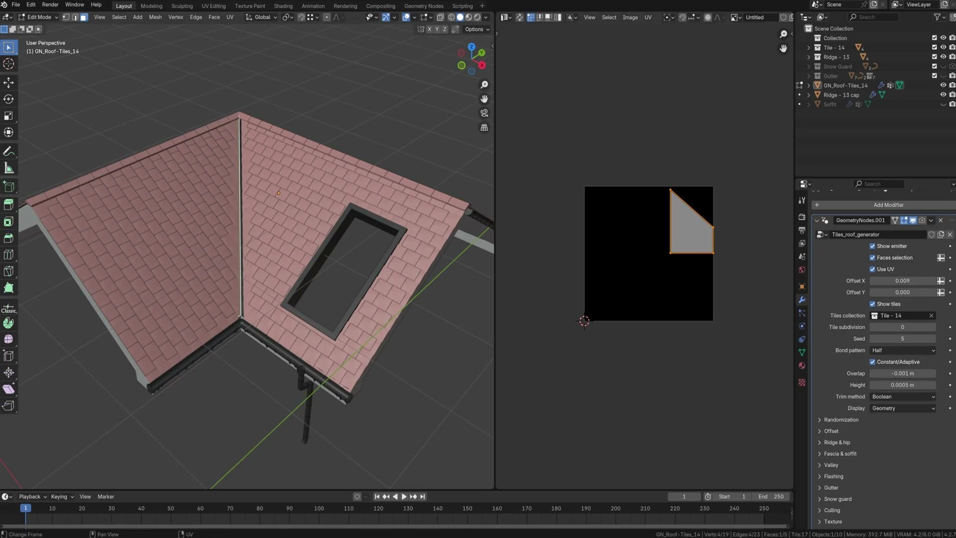
Open the UV editor and drop the roof mesh into edit mode. Every face of the roof is now its own UV island. Select a single island, rotate it 90 degrees, and that face's tiles rotate with it. You can also translate the island to shift just that face's tiles, all without touching the others.
It's the most powerful way to control tile direction on a complex roof, but it is fiddlier. For straightforward roofs I'd stick with the plain X/Y offsets and reach for Use UV only when a specific face needs to break from the rest.
How the tile collection randomises across the roof
The Show Tiles toggle turns the tile layer on and off, and right below it sits the Tiles collection slot. Whatever collection you point this at, the roof generator will scatter randomly across every face of the roof.
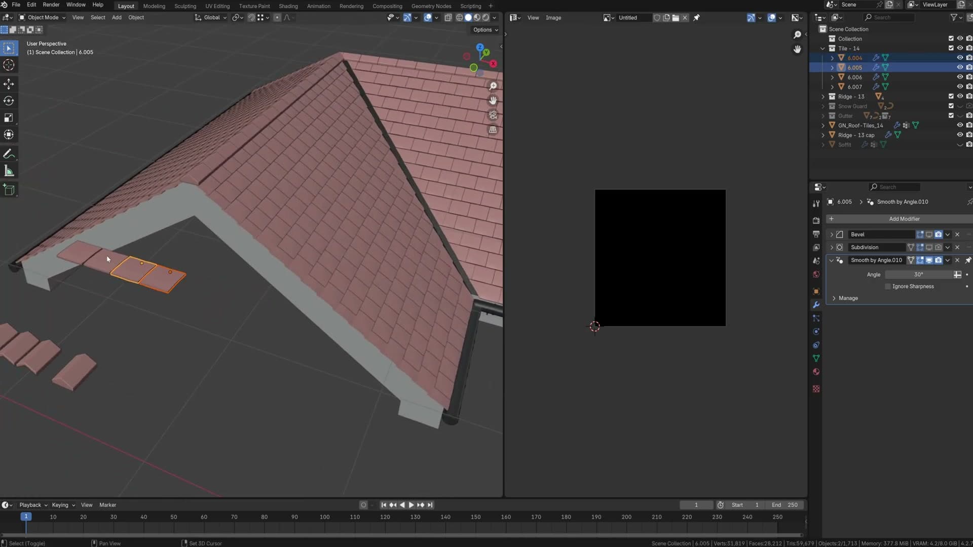
Open the collection in the outliner and you'll find it holds several tile objects. Pick that collection on the generator and all of those variations are randomised across the surface: one tile here, a different one there. That's what stops a roof reading as a tiled clone-stamp.
If you want to see exactly what a single tile looks like before adding variation, remove the others from the collection temporarily so only one remains. The generator will then place that same tile everywhere, which is the easiest way to dial in the origin point and overlap before you reintroduce the rest of the variations.
Why the tile origin point controls overlap
The single most important thing to get right on a custom tile is the origin point. The roof generator uses each tile's origin as the line where the next tile up will start overlapping it, so the gap between origin and the top of the tile is the visible overlap distance.
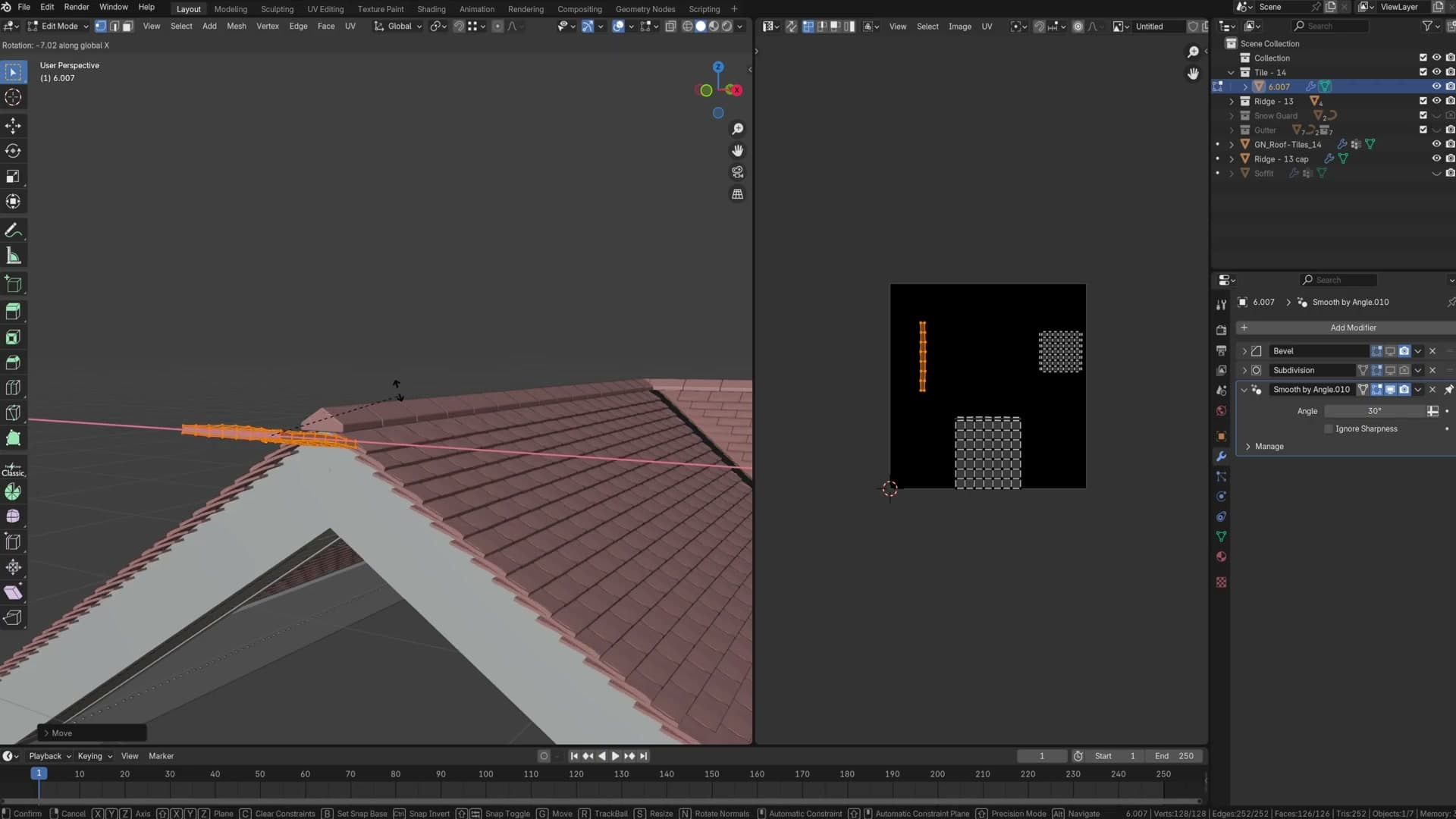
To prove it to yourself, drop into edit mode on a tile, press A to select all, and slide the geometry away from the origin. The origin stays put but the overlap point moves with the mesh. Push the geometry up and tiles bunch tightly; pull it down and they stretch out. That's how you get more tiles on a long roof, or more spacing on a short one.
Scaling needs the same care. If you grab a tile and scale from its centre, the origin ends up floating off the mesh and you'll get gaps where the tiles meet. The clean way is to snap the 3D cursor to the bottom edge first: select that vertex or edge, hit Shift+S and choose Cursor to Selected. Then set the pivot to 3D Cursor, press A and scale. The tile grows from the bottom edge and the origin stays exactly where the generator expects it.
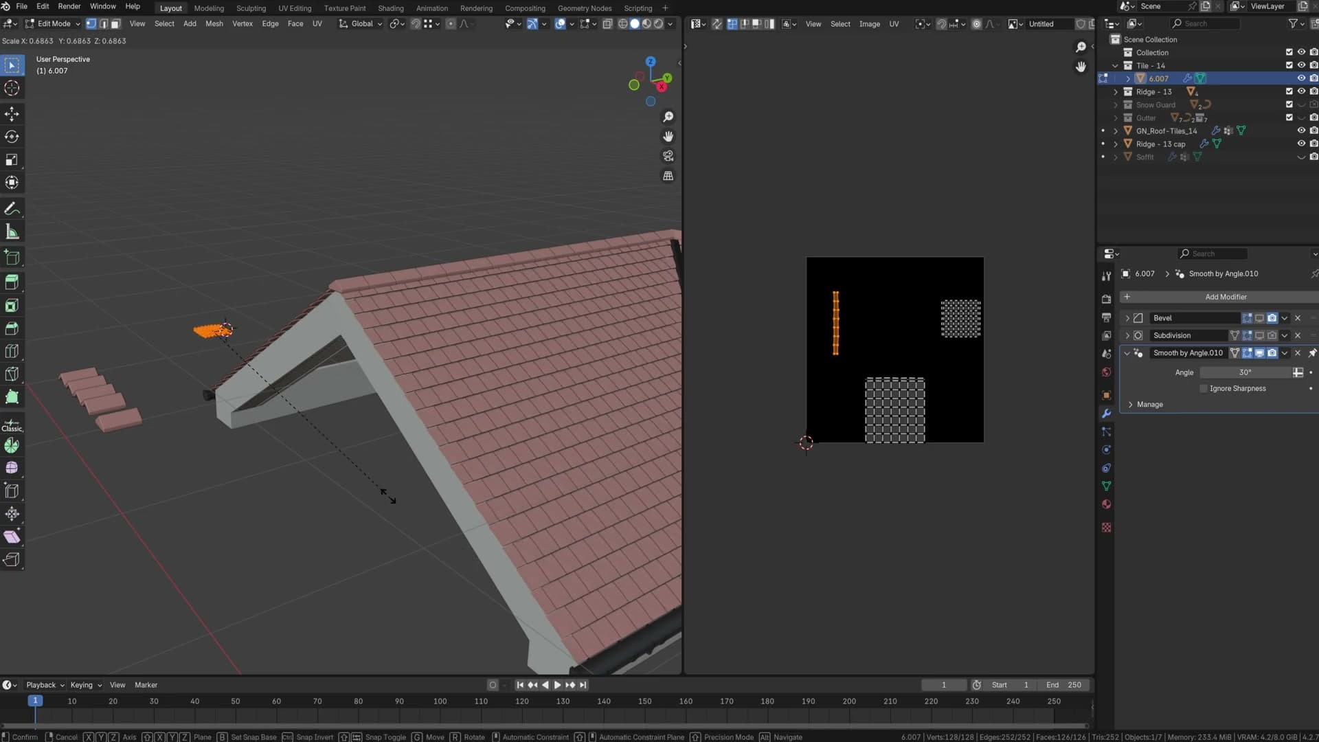
The takeaway is genuinely simple: model your tile, place the origin at the bottom edge where you want the next tile to start overlapping, drop the object into the tiles collection, and the roof generator will scatter and overlap it correctly without any further setup.
If you're still seeing gaps after scaling, the origin has drifted off the mesh. Move it back to the bottom edge and the overlap snaps back into place.
Tile subdivision, seed, pattern, overlap and height
The per-tile sliders that fine-tune how the scatter behaves, including the subdivision trick for stubborn Boolean failures, pattern modes (half / straight / quarter) and per-row overlap.
Tile subdivision as a Boolean rescue
Boolean trim is the most accurate way to clip tiles to the roof edge, but Blender's Boolean solver is occasionally janky and you'll get a stray tile poking through the surface or refusing to cut cleanly. The Tile Subdivision slider exists specifically to rescue these cases.
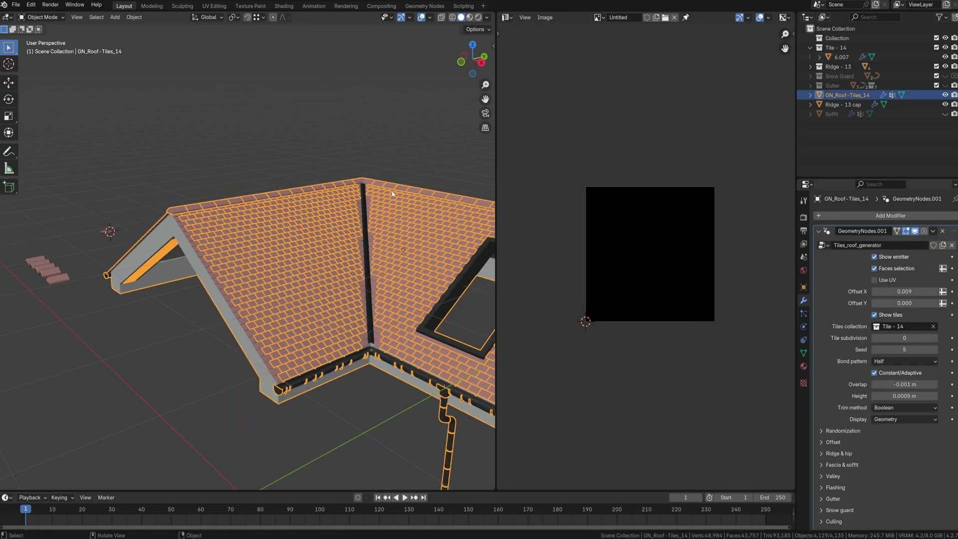
When you spot a misbehaving tile, bump tile subdivision up by one level and check whether the Boolean now resolves. The extra geometry gives the solver more vertices to work with, which is often enough to make a stubborn cut behave. If a single level doesn't fix it, you can also drop into the tile mesh itself and add subdivision there.
You won't usually need this on simple, mostly-square tile shapes. Those Boolean cleanly without help. Keep the slider in mind as the first thing to try whenever something looks wrong with a single tile rather than the whole roof.
Seed and tile pattern (half / straight / quarter)
The Seed slider re-rolls the per-tile randomisation. Drag it to shuffle which tile variants land where, until the distribution looks natural for the roof you're building.
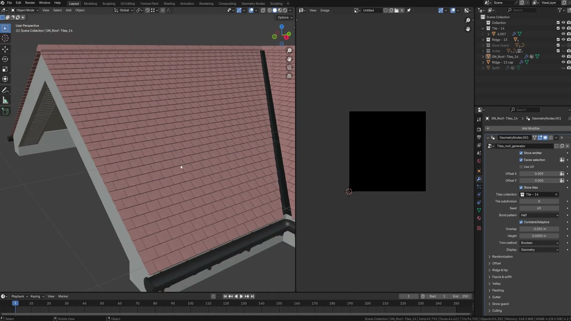
Tile Pattern sets the row-to-row offset. You get three options: Half, Straight and Quarter. Half staggers each row by 50% of a tile width, straight stacks every row flush, and quarter offsets by 25%.
Which pattern you reach for depends on both the roof and the tile mesh itself. Some tile profiles only sit correctly when staggered. They simply won't tile straight without visible seams, so if a tile looks broken in one mode, switch the pattern before you start tweaking anything else.
Overlap and height per tile
Some tile profiles (anything with a curved or stepped front edge) need to sit partly under the row above them. Tile Overlap controls that. Increase the value to push each tile back underneath its upper neighbour until the visible exposure looks right and there are no gaps showing.
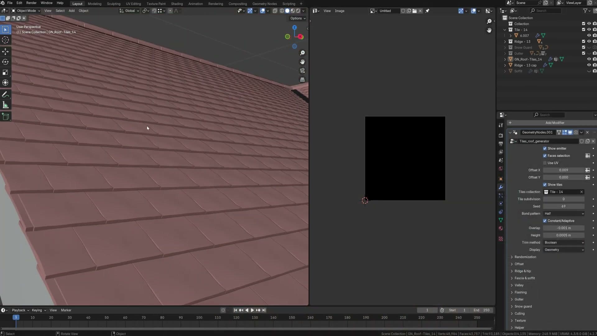
Tile Height simply lifts the whole scatter away from the roof surface. Use it when the tiles are clipping into the underlying mesh, or when you want a touch of breathing room between the tile geometry and the roof deck.
Trim methods: None, Boolean and Alpha Map
The three ways the generator can clean up tile edges: Boolean for final renders, None for the fastest viewport, Alpha Map for huge roofs. And the critical Cycles transparent-bounces setting that makes alpha map viable.
None vs Boolean trim and when each wins
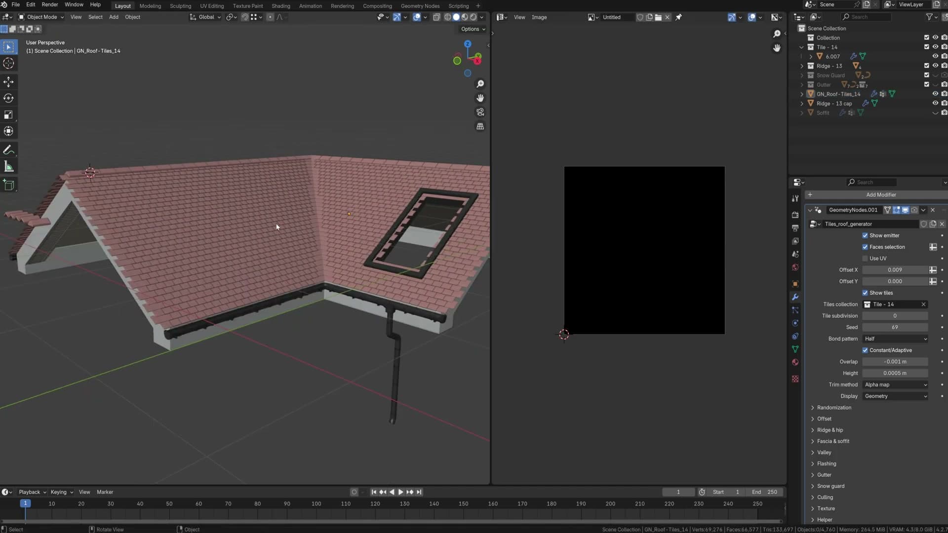
Boolean is the trim method to settle on for final renders. With it active, the tile geometry is cleanly cut at the roof edge, so what you see in the viewport is what you get when you render. No guessing at the silhouette and no surprises once the camera moves in.
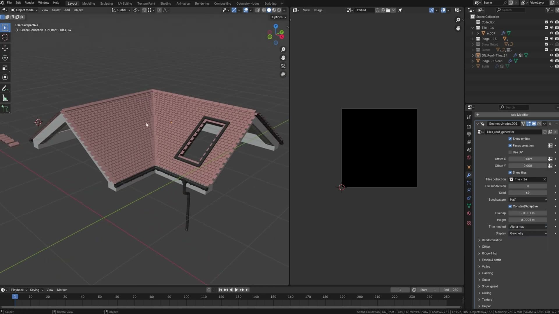
My rule of thumb: once the roof shape is locked in and you are no longer moving the underlying mesh around, switch to Boolean and leave it there. The other trim modes exist to keep the viewport responsive while you are still iterating, but Boolean is the one that produces the cleaner result on the way out.
Alpha Map trim for speed on huge roofs
Alpha map is the third option, and it exists for one specific scenario: a very big, very complicated roof where you need render-preview speed without paying the Boolean tax. Drop into render preview and the tiles read as cleanly trimmed at the roof edge, but no actual cutting is happening behind the scenes.
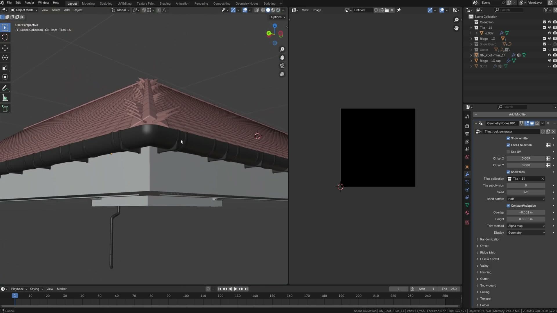
Instead, an alpha map applied to each tile is doing the trimming. The geometry still extends past the roof boundary, but the alpha texture hides everything outside it. Switch back to solid shading and the underlying mesh looks janky and jagged, with tile geometry visibly poking out where it should not be. From a typical camera angle in render preview, that mess reads as a perfectly clean roof.
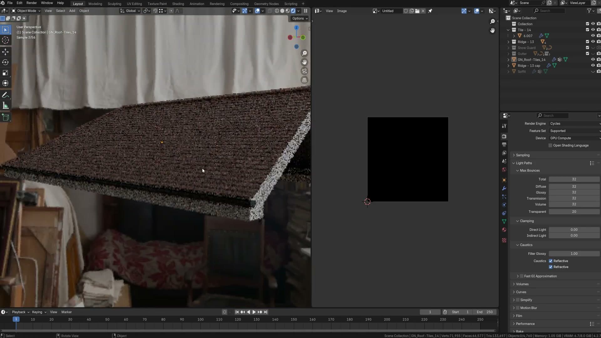
The pay-off is the speed. Because the modifier is not running any Boolean calculations, the whole stack evaluates much faster. That's the whole point on a huge roof system. There is a catch with overlapping tiles in Cycles, though, and that is what the next sub-lesson is about.
Why transparent bounces matter for alpha map mode
Alpha-map trim has a catch, and it lives in Cycles. Tiles that get hidden by the alpha map still exist as geometry. At any angle where tiles overlap heavily (on a tiled roof that means sighting flat along the surface) you can be looking through 20 or more transparent surfaces stacked on top of each other.
If your Cycles transparent bounces are set low, those stacked transparent faces will not fully resolve and you will see black edges showing through the roof. In the video I walk through this on screen: at a value of 5 the overlapping faces start to appear, and at 1 they are unmissable. The fix is to bump transparent bounces well above the default in Render Properties → Light Paths until the black edges clear.
The visibility of the problem also depends on the camera angle. Shoot the roof from a normal viewer's height and you will rarely have any issues, because you are only looking through one or two tiles. Tilt the camera so you are sighting flat along the surface and that is when the 20-plus overlaps stack up and you need the higher bounce count to clear them. A bit of fine-tuning per shot is sometimes needed, but a typical roof angle should be fine.
Tile randomisation and edge offsets
Adding subtle position, rotation and scale variation for a weathered roof, plus the per-edge offset attributes that let you stop overhang at specific edges.
Min/max randomisation on position, rotation and scale
Tile randomisation lives in its own panel and gives you minimum and maximum values for three transforms: translation, rotation and scale. Turn it on and the generator jitters every tile independently within the ranges you set. The gap between a freshly laid roof and one that has been sitting on a cottage for fifty years comes down to exactly this.
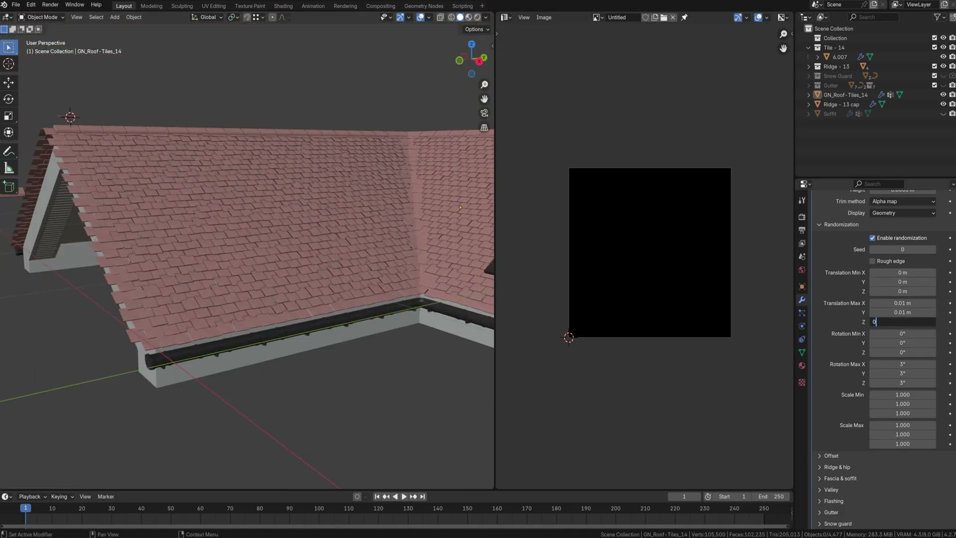
Start with translation. A maximum of 0.01 moves each tile by roughly one centimetre in Blender's default units. Small enough to feel natural, large enough to break up the regularity. Push the rotation maximum up at the same time and the roof starts to read as a properly broken, weathered surface rather than a perfect grid.
Drop the Z component of translation to zero. You don't want tiles floating upwards off the surface. What you do want is a gentle sideways shuffle along the roof plane, so leave X and Y free and lock Z to 0.
Finally bring in scale. A slightly smaller minimum and a slightly larger maximum gives you a mix of tile sizes across the surface. Combined with the position and rotation jitter, the result is the broken-roof effect: every tile sits at its own angle, its own height and its own size, and the eye stops reading the pattern as procedural.
Edge offsets and the remove_offset attribute
Turn randomisation back off and switch the trim method back to Boolean so you can see the offsets cleanly. The Roof Generator gives you three offset controls: an overall edge offset that pushes every tile outwards uniformly, a dedicated bottom-edge offset for when you want the tiles to hang further down past the eaves, and side offsets that push the tiles out past the gable edges.
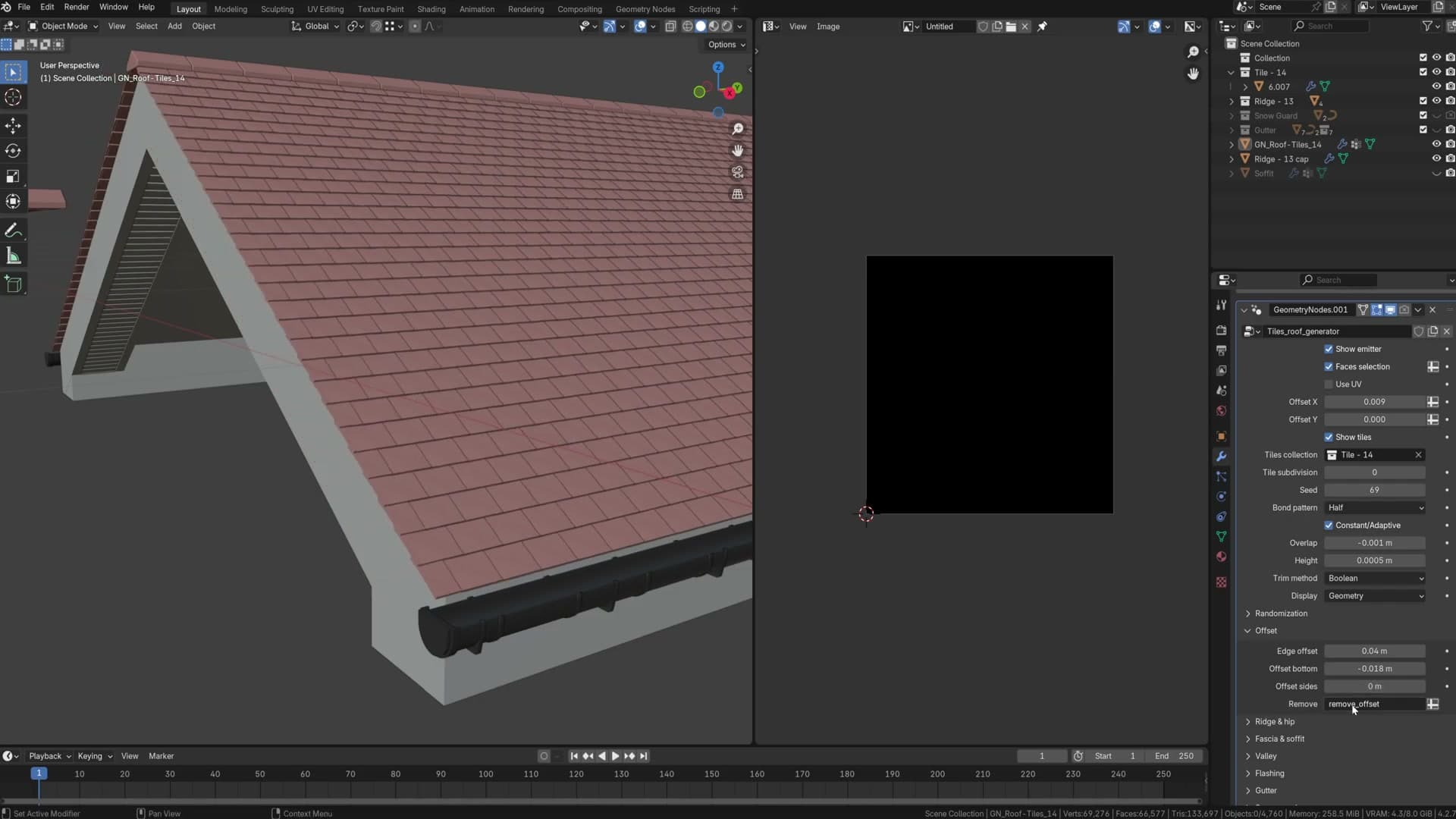
Drag the side offset up and the tiles march out past the wall on both sides. That is usually what you want on a gable end, but not always. Sometimes one edge butts up against another roof section or against a wall, and the overhang there needs to be killed while the opposite side keeps its offset.
That is what the remove offset attribute is for. It works per-edge: drop into edit mode, select the single edge where you don't want overhang, press F3, search for Set Attribute and run it with the attribute named remove offset. The generator reads that flag and pulls the offset back to zero on that edge only, leaving the rest of the roof alone.
Hip and ridge tiles with end caps
Two separate collections for the ridge run and the hip run, plus a dedicated cap object for the decorative end tile. Walks through scaling, overlap and overhang attributes.
Ridge collection and end-cap object
Ridges are wired up the same way as the main tile field: there's a dedicated ridge collection that the generator scatters along every ridge edge it finds. Drop whichever tile object you want to use into that collection and the addon will pick from it as it walks the run.
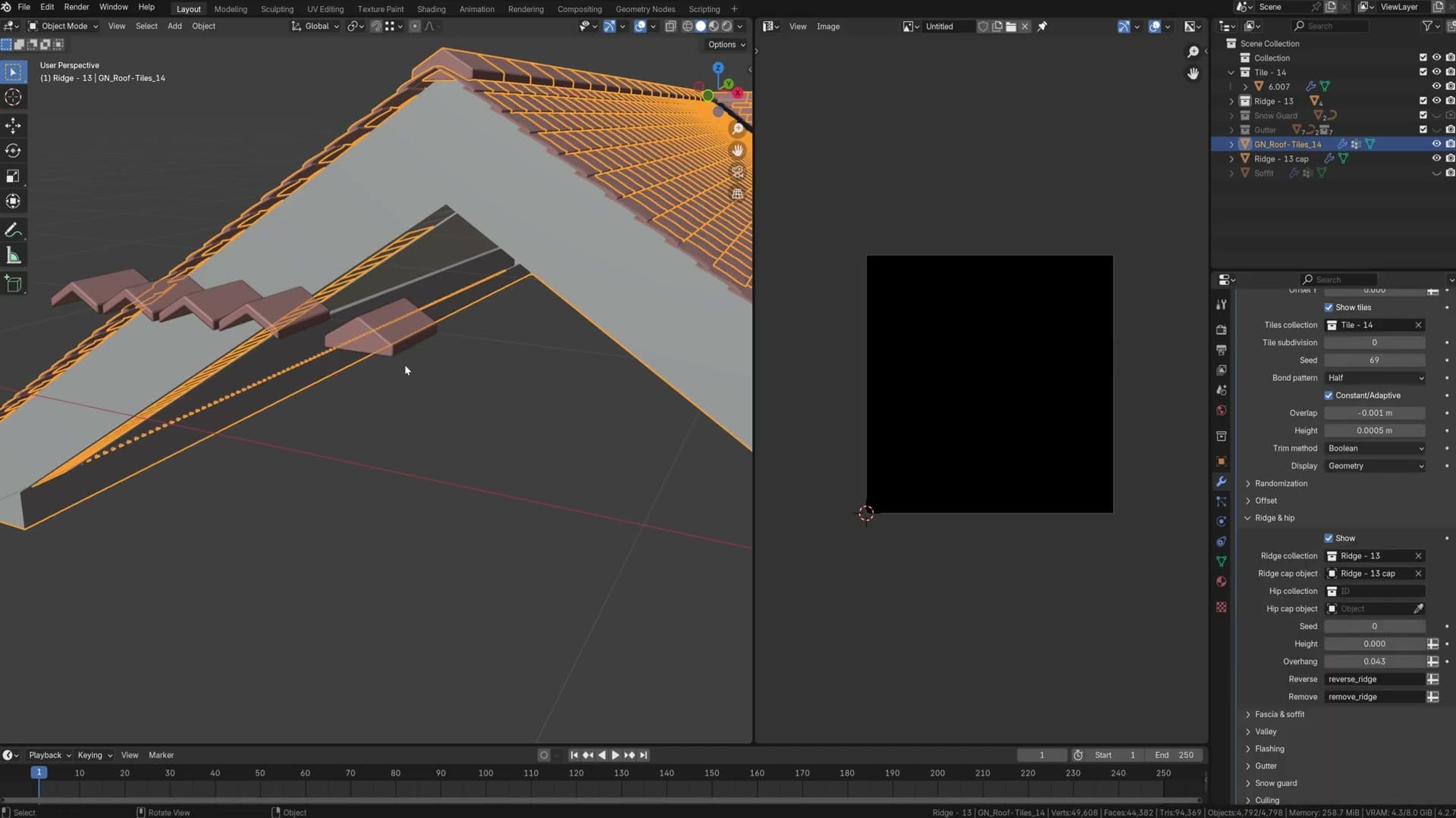
Alongside the running tile there's a separate cap slot. The cap is the object that sits on the very end of each ridge, usually a tile with a flat closing edge so the run terminates cleanly. You can just as easily point the cap at a more decorative piece if you want a feature tile finishing the ridge.
Building a separate hip collection
Hips often use a different profile to the ridge, so the generator gives them their own collection. Make a fresh object (a quick cube is enough to demonstrate), move it into a new collection, and then assign that collection to the hip slot on the generator. The placeholder along each hip edge swaps over to the new object straight away.
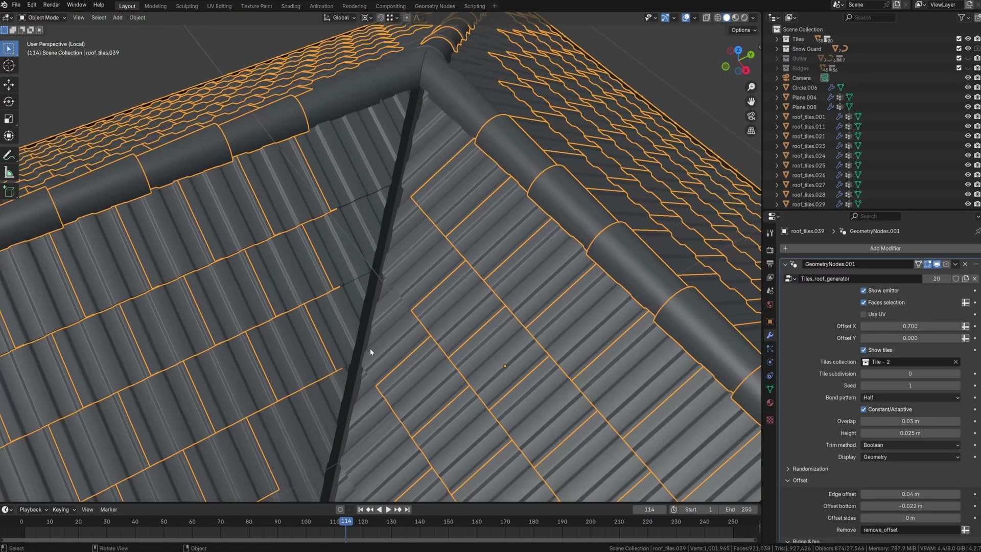
Sizing the tile down is a two-step move: scale it in object mode, apply the scale, then scale it again so the generator sees its true dimensions. From there you can switch into edit mode and start refining the shape against the roof.
Origin position is what controls overlap. The generator drops a tile at every step along the hip edge using that object's origin as the anchor, so if the origin sits in the centre of the mesh the tiles butt up against each other with no overlap at all. For most ridge and hip profiles you actually want overlap. The bottom of one tile needs to tuck inside the top of the next so the run reads as a continuous cap rather than a row of separate pieces. Move the origin towards the overlapping edge of the mesh in edit mode and the tiles immediately start nesting into each other.
Hips get their own cap object too. Duplicate the hip tile, pop it into the scene collection, reshape the end and assign it to the hip cap slot. The generator drops that variant on each hip terminus rather than the running tile. If you leave the cap empty the generator falls back to using the hip collection for the end as well.
Driving ridge overhang with a custom attribute
Ridges and hips have their own parameters sitting under the same panel. The two you'll reach for most often are height, which lifts the whole ridge profile up off the roof, and overhang, which pushes the tiles further past the edge they sit on. Nudge the overhang up and the ridge or hip tiles project a little more, sitting proud of the slope instead of tucked tight against it.
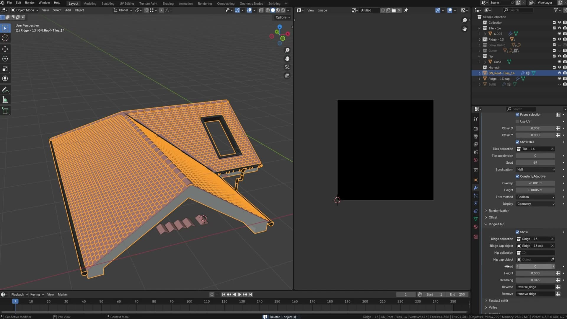
Like almost every other slider on the Roof Generator, height and overhang can both be driven by attributes rather than a single global value. That means you can vary the overhang along a single ridge, or reduce it on just one end where the geometry underneath demands it, by setting the value as a custom attribute on the specific edges you want to change. No need to commit the whole roof to one number.
Fascia and soffit board generation
The wooden trim that closes off the eaves, including the plank geometry on the soffit underside, height padding for gaps, and the material slots for each part.
Fascia board height, depth and material
The fascia and soffit are the trim that close off the bottom edge of the roof: the vertical board you see running along the eaves and the horizontal panel tucked underneath it. You can switch the whole assembly off if you want a bare tiled roof, but most real buildings have something here, so leaving it on is the usual choice.
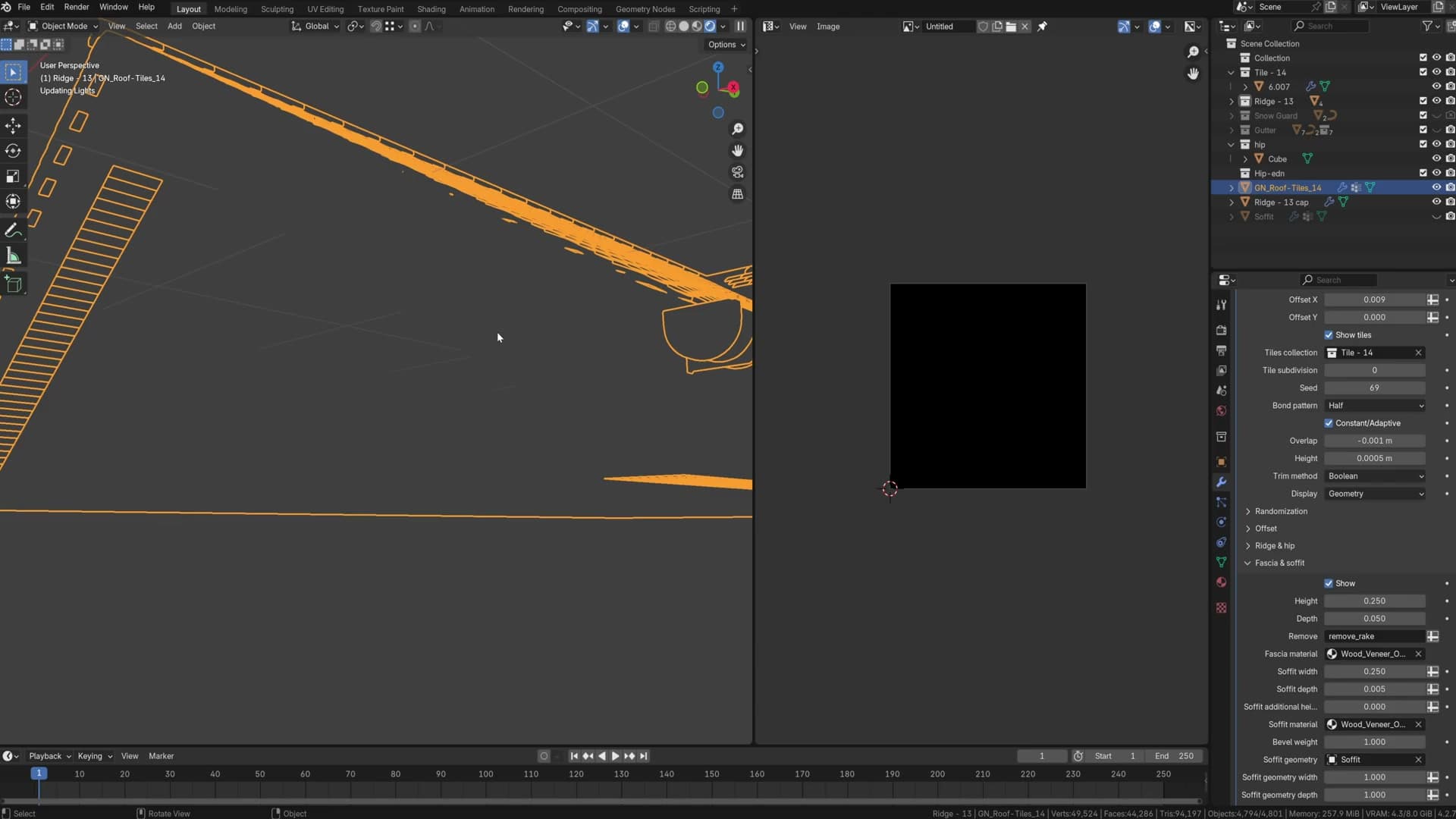
Working down the panel, you get a height, a depth and a material slot for the fascia board itself. In the demo file the material slot has a wood texture wired up that unwraps neatly along the edge, but you can swap it for anything you like: metal trim, painted board, render. Whatever the building calls for.
There is also an additional height value tucked alongside the main controls. If your roof leaves a small gap between the tile line and the top of the fascia, push this value up until the board closes the gap cleanly. The exact amount depends on the geometry of the building underneath, so treat it as a per-project tweak rather than a fixed number.
Soffit plank geometry on the underside
The soffit is the piece that sits horizontally underneath the fascia, capping off the underside of the eaves. It carries its own material slot (in the demo file it uses the same wood as the fascia) and it can be styled independently if you want a different finish on the underside.
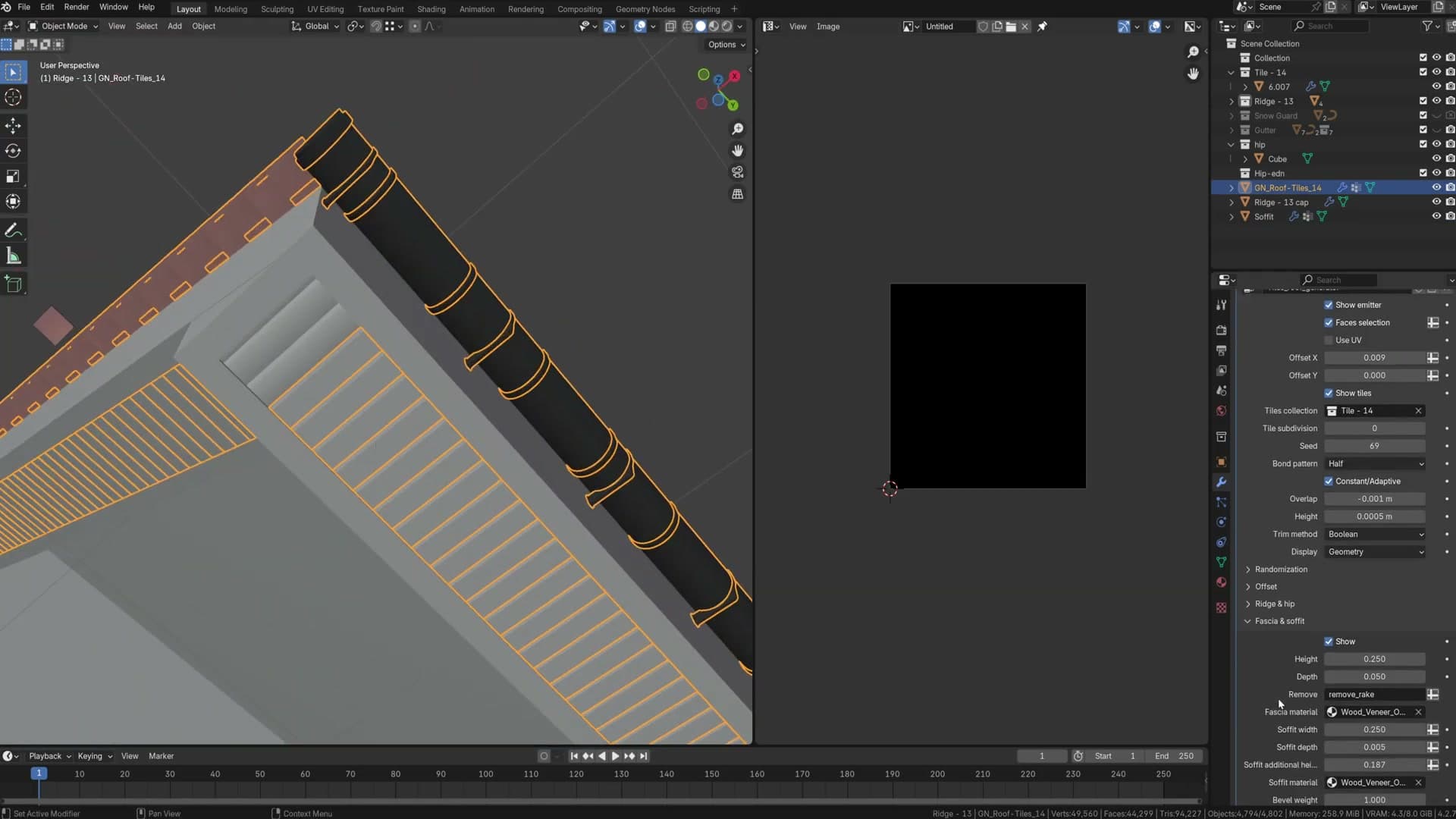
Unlike the fascia, the soffit can carry real geometry rather than just a flat surface. Drop into the referenced plank object and you'll see a simple plank shape; the generator slots an instance of that plank along the underside wherever the soffit runs. Turn the plank toggle off and the geometry disappears, leaving a flat soffit panel behind.
You don't always need planks down there. Plenty of roofs use a plain board. But it's the right hook when the building has a detailed soffit, a vented grill or any other piece of trim that needs to repeat along the underside. Pick the soffit option in the dropdown and the plank you've nominated gets placed automatically. From there you can adjust the width and a handful of basic parameters to match the spacing on your reference.
Valley channels and window flashing
Adding rain-channel valleys with per-edge width attributes, then flashing around roof openings like skylights and dormers.
Valley width and the add_valley / remove_valley attributes
Valleys are the internal roof edges where two pitched slopes meet inwards, the channels rainwater runs down on its way to the gutter. The generator exposes a single Valley Width control for the common case where every valley on the roof is the same size, which keeps things simple when you don't need to vary anything.
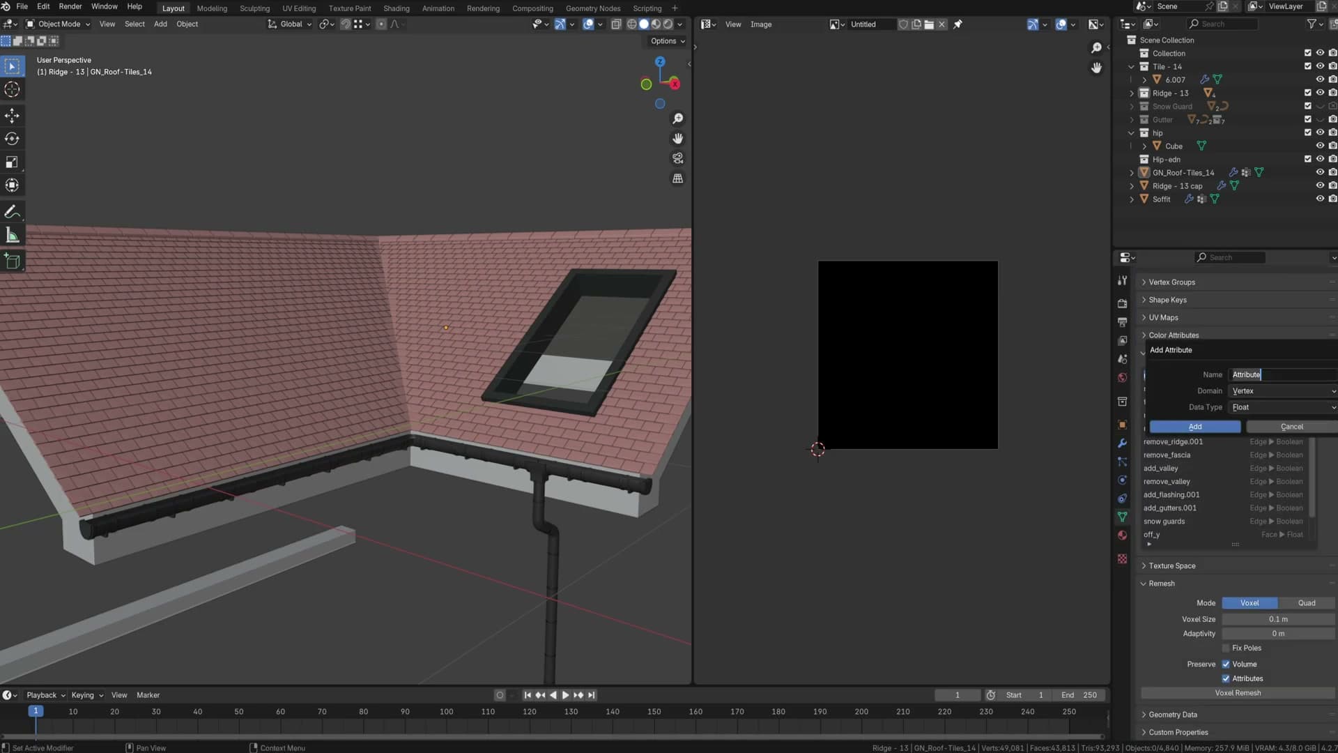
For more complicated roofs that need different widths on different runs, drive the width per edge instead. Click the attribute button beside the Valley Width field and give the new attribute any name you like. I call mine valley width. Set the domain to Edge and the type to Float so you can dial in a range of values rather than a simple on/off.
Drop into edit mode with Tab, select the valley edge you want to change, press F3, search for Set Attribute, type valley width in the name field and enter the width you want for that edge. Repeat for each valley that needs its own size. Every other valley keeps falling back to the default slider value.
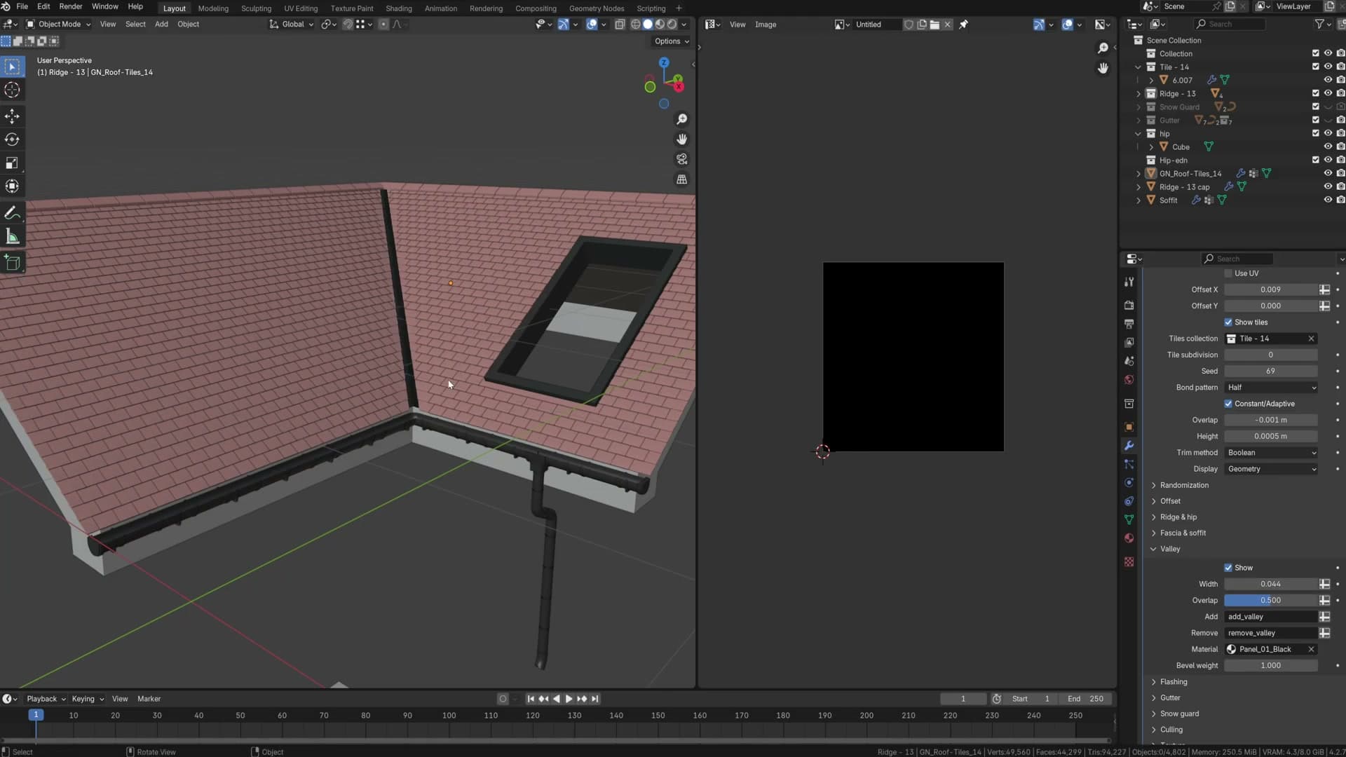
Two further attributes are already exposed without you having to create them: add_valley and remove_valley. If the generator has produced a valley channel somewhere it shouldn't be, select the offending edge, run Set Attribute with remove_valley, and that section of the channel disappears.
Flashing geometry around a window hole
Flashing is the strip of trim that wraps the edges of a hole cut through the roof, most often a skylight, but the same applies to dormer windows or any other rectangular opening. Without it, the generator tries to push a soffit into the cutout and the geometry around the hole comes out distinctly wonky.
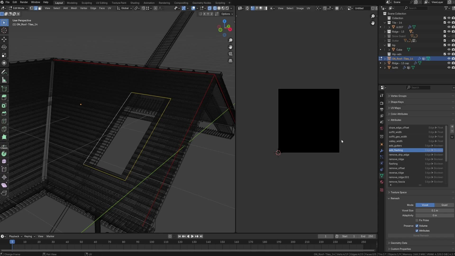
To fix it, drop into edit mode and select every edge around the opening. Press F3, choose Set Attribute, and run add_flashing on the selection. The soffit attempt is replaced by a clean flashing band that follows the perimeter of the hole, and toggling the result off and on is the quickest way to confirm the attribute is reading the edges you expect.
Once flashing is switched on for the right edges, the generator exposes a panel of parameters for the strip itself so you can match the profile, depth and overhang to whatever metalwork your reference shows.
Gutters, downpipes and wall supports
The most complex assembly: the gutter collection, the snapping vertical downpipe, fillet radius for both runs, and the 'supports' vertex group that places wall brackets.
Gutter collection and add_gutters attribute
The Roof Generator ships with gutters built in, so you don't need to model them separately. The same performance-optimised version that's being rolled out as a standalone iMeshh release is already baked into the roof system, so you can ignore the standalone product if you're using the generator.
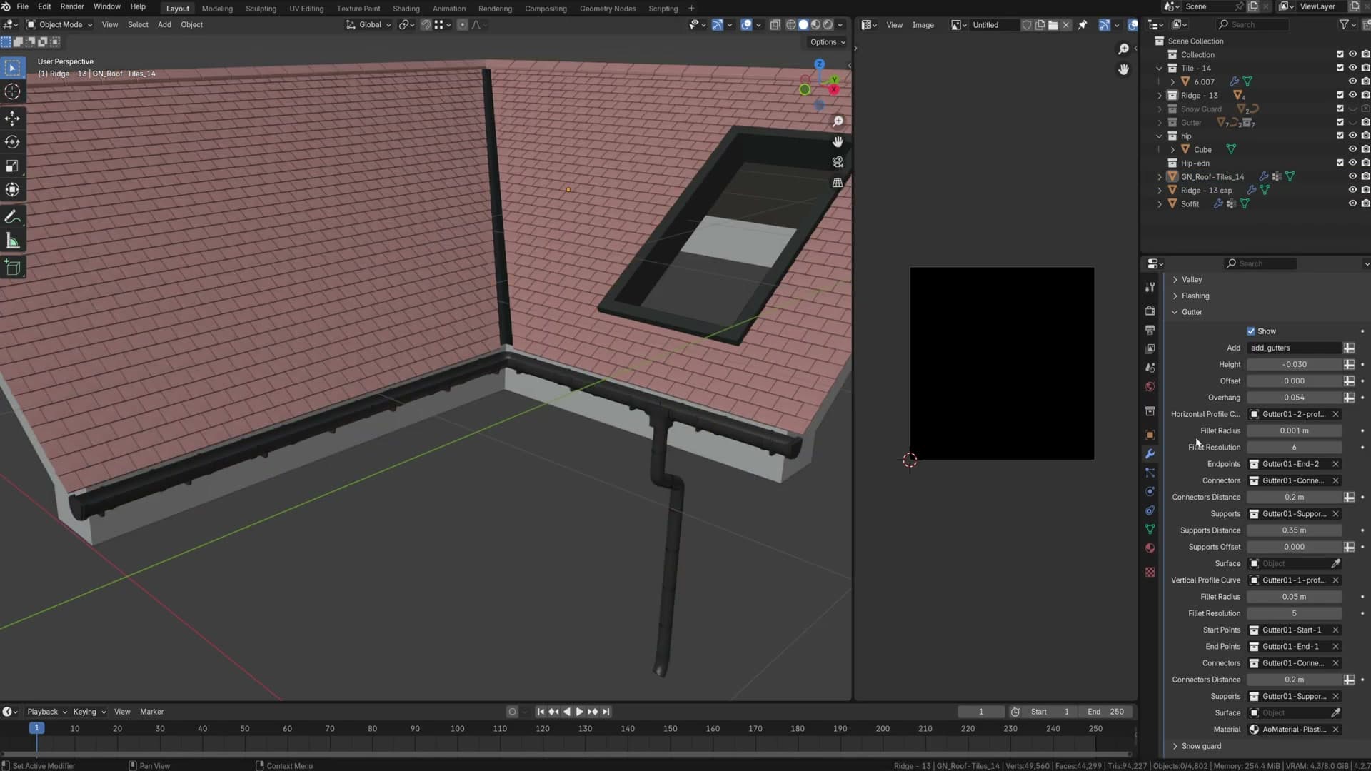
Open the gutter collection and you'll see all the parts the generator pulls from. They're being renamed to horizontal and vertical so you know which side of the run you're editing. The two need slightly different geometry. If you have an iMeshh subscription you can drop your own gutter assets into these collections to swap the profile out for something else.
To control where gutters appear, use the add_gutters attribute, the same per-face workflow used elsewhere in the generator. In edit mode, select the face you want gutters on (or off) and set the attribute. In the demo I switch it off on a single face so the gutter only runs along one eave instead of wrapping the whole roof.
Vertical downpipe auto-snapping to the gutter run
The vertical downpipe is the simplest part of the whole gutter assembly. You don't need to model it carefully into place. You just need a section of pipe geometry sitting loose in the scene, completely disconnected from any other mesh.
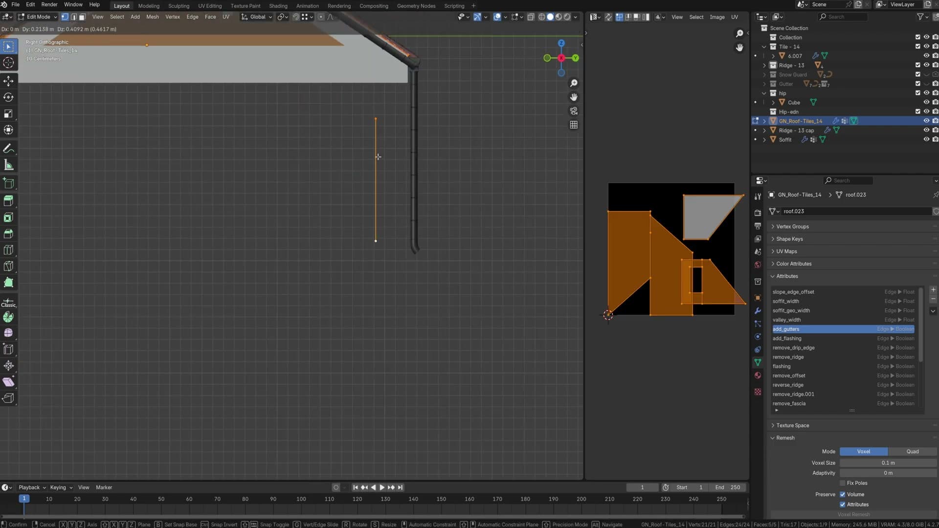
Once that loose geometry exists, the generator will automatically snap it onto the nearest horizontal gutter run. Drag the pipe across the building and it pops onto whichever section is closest, and it auto-rotates so the joint between vertical and horizontal sits correctly. You only have to rough-position the pipe; the snap does the precision work.
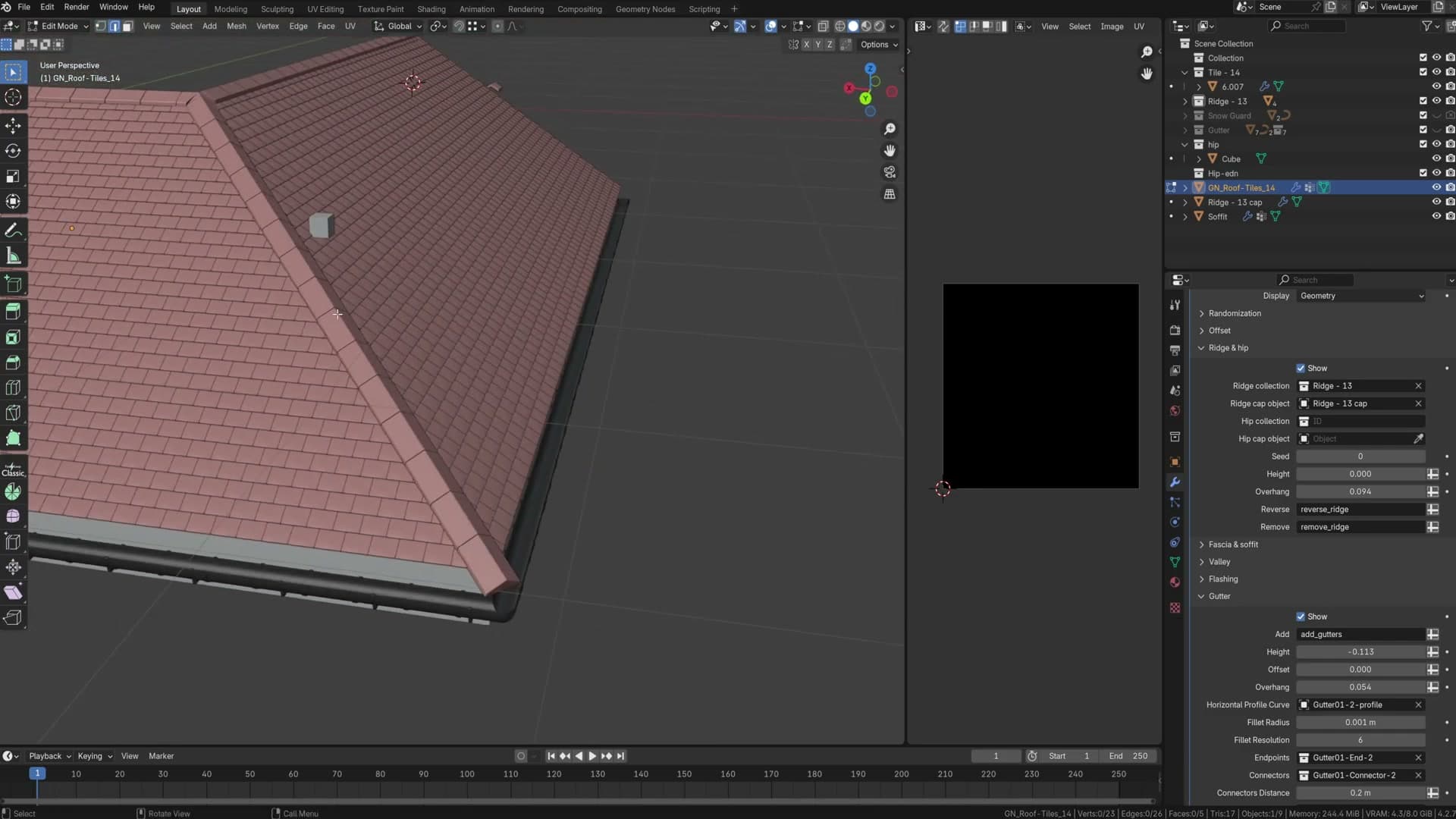
From there it's a matter of shaping the pipe so it carries down the wall. In the video I sketch the typical L-shape you'd expect on a real building: out from under the gutter, then straight down to the ground.
Fillet radius for horizontal and vertical sections
The horizontal gutter has a fillet radius parameter that controls how rounded the gutter's cross-section is. Push it up and the gutter curls in tighter on itself; you may then need to nudge the whole assembly out from the wall slightly so the rounder profile doesn't clip.
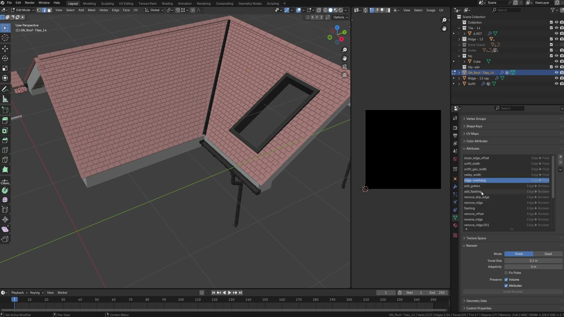
Changing the horizontal fillet radius propagates through the rest of the run, so re-enabling gutters on another face and tweaking the radius is a quick way to see how the curve carries through the entire assembly.
The vertical downpipe has its own fillet setting (being renamed to vertical fillet radius to keep it distinct from the horizontal one) that controls the same kind of roundness on the pipe. Adjust it independently to dial in the downpipe profile without disturbing the gutter above it.
Placing wall supports via the 'supports' vertex group
The wall supports (the brackets that strap the gutter back to the building) are placed differently from everything else in the generator. Because the addon can't guess where your wall is, it doesn't use a face attribute for this. Instead it reads from a vertex group called supports.
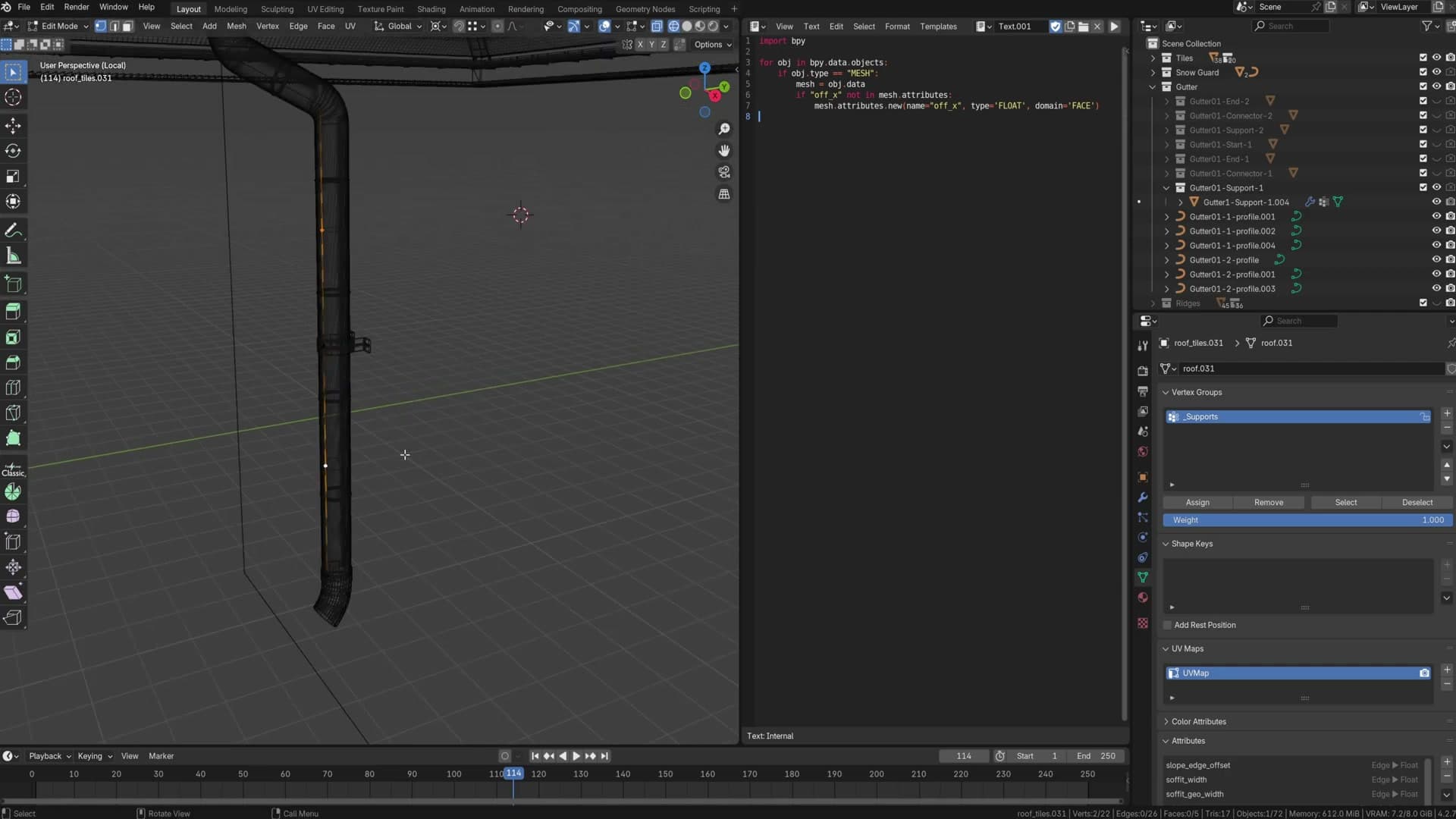
To set one up, open Object Data Properties on the roof object, add a new vertex group and name it supports.
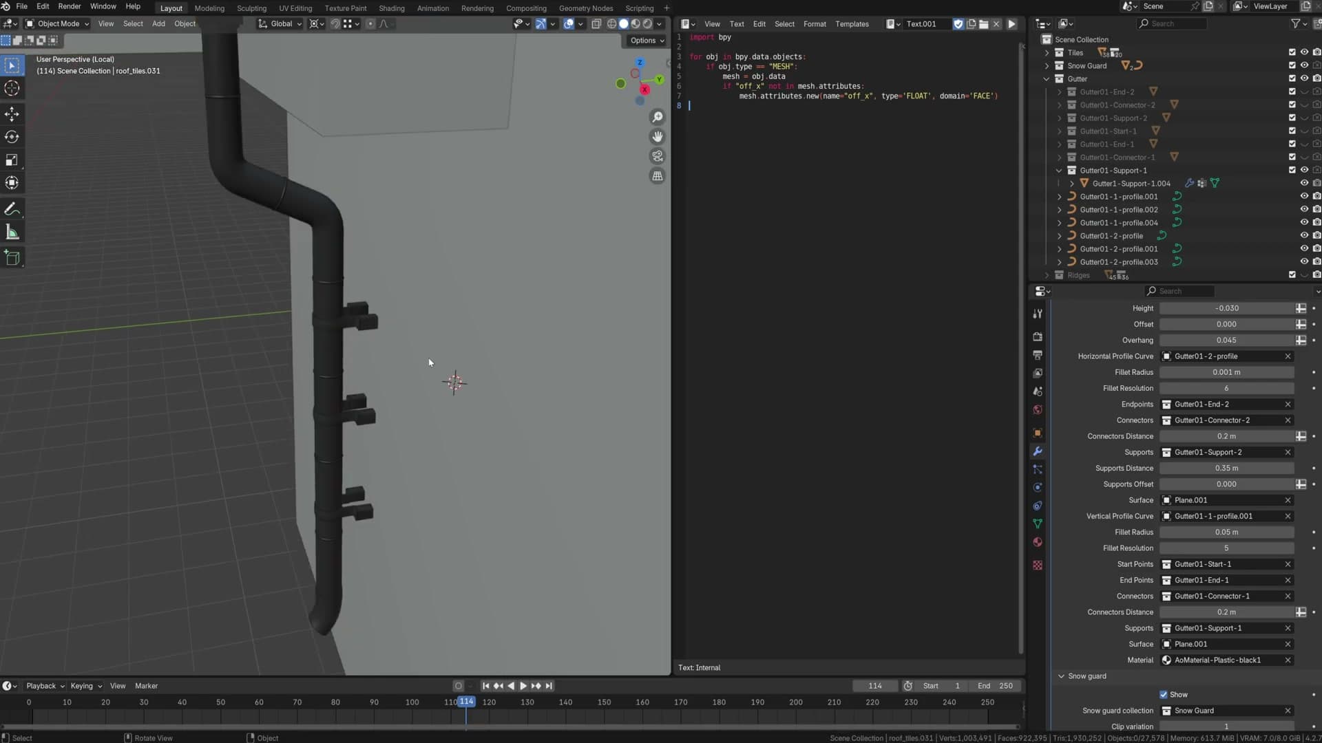
Then drop into edit mode and add vertices at the points where you want each bracket to sit. Assign those vertices to the supports group and the brackets appear at exactly those positions. Move them up or down the gutter to space the brackets however you like.
If the bracket vertices don't quite reach the wall, the generator will extrude the last face out to the wall surface for you, so the support always meets something solid. That said, I'd model the vertices flush against the wall in the first place. That's how a real bracket sits, and it avoids relying on the extrusion as a safety net.
Snow guards: rail and clip variants
Two snow-guard types: single-rail along the eave or scattered clip grids with adjustable rows and columns.
Snow rail using the snow_rail_profile curve
Enable snow guards from the Roof Generator panel and the addon scatters them along the eave. There are two shipped variants in the snow guard collection, and the Type dropdown swaps between them. Variation cycles randomly through whatever sits inside that collection.
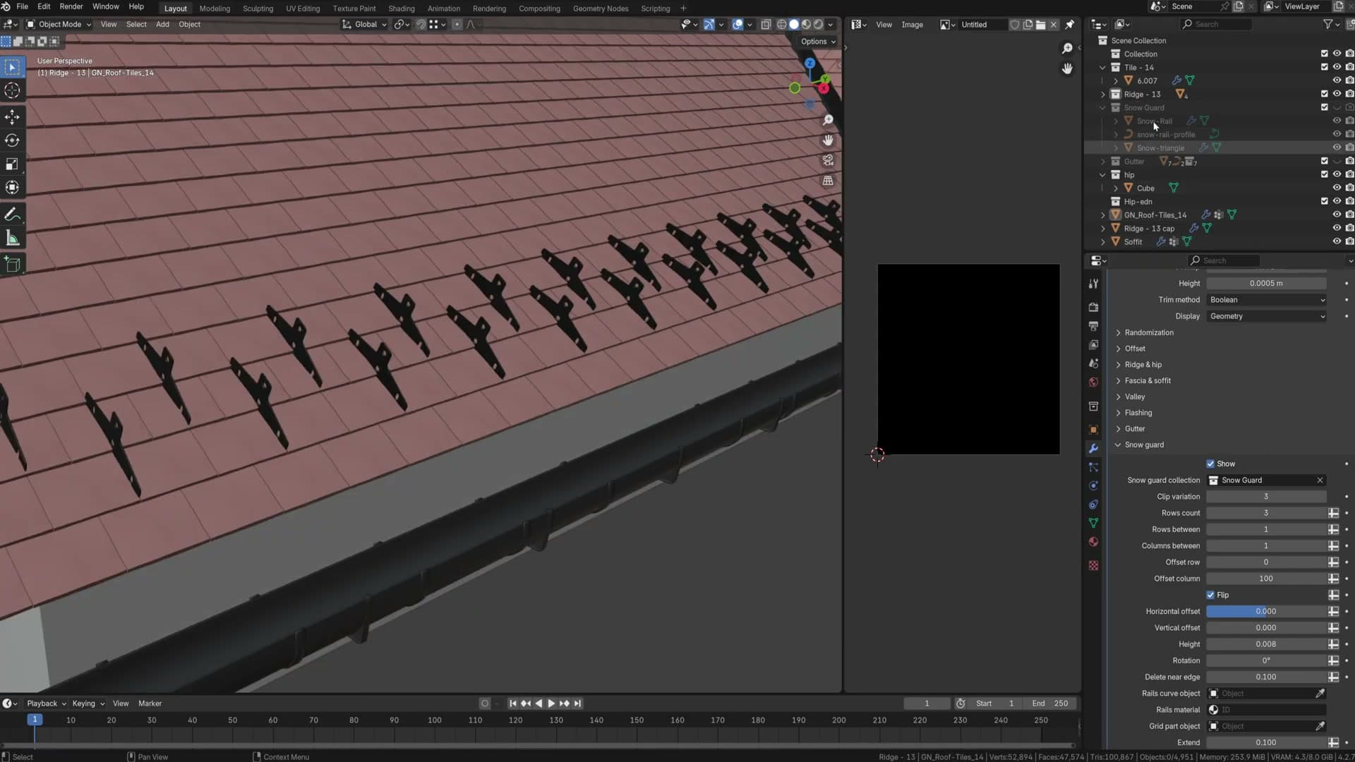
The first variant is built for a continuous rail. With the rail-style snow guard selected, scroll down to Rail Curve, type rail into the search, and pick the matching profile from the list. The generator sweeps that profile along the bottom edge to form a single uninterrupted metal bar.
In almost every case you only want one row of rail along the bottom of the roof, so drop the row count back to 1. That leaves a clean horizontal snow guard sitting just above the gutter line.
Clip-style snow guards in rows and columns
If you prefer individual clips to a continuous rail, switch the snow-guard variant and turn the rail curve back off. Each clip is then scattered as a discrete instance rather than swept along a curve.
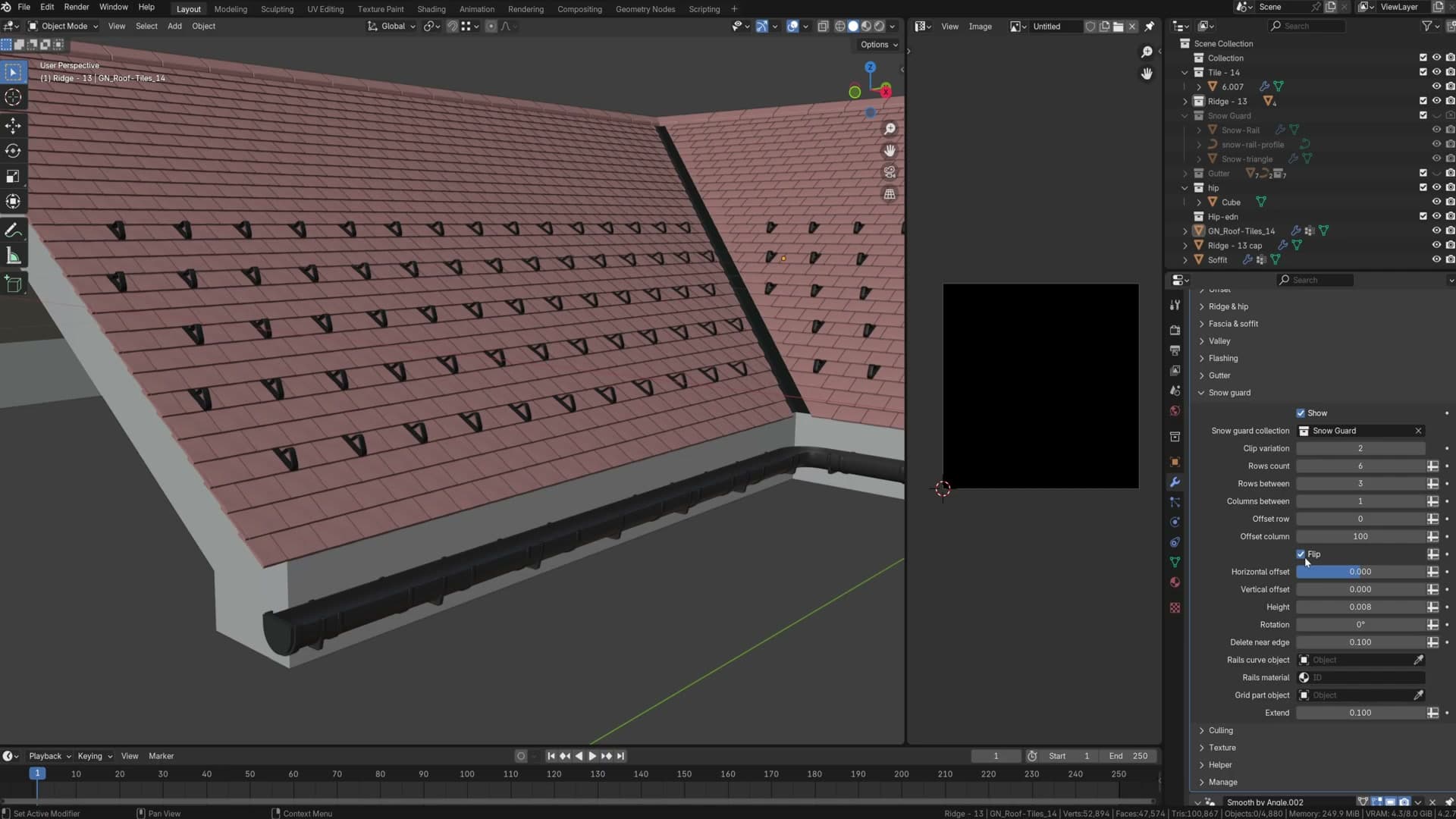
Use the Rows count to stack the clips up the slope and the Column Offset to stagger every other row so the pattern doesn't look gridded. You can also nudge the whole grid up or down the roof to land the clips exactly where you want them, typically tucked just under a course of tiles.
The shipped presets are tuned for a roof at the default pitch, so a standard setup should drop in and work. If your roof is steeper or shallower than the preset assumes, expect to fine-tune the row spacing and vertical offset to keep the clips sitting flush against the tiles.
Camera culling to save VRAM on big scenes
Self-culling tiles that can't be seen by the active camera, with the option to pad the camera frustum for safety.
Enabling self camera culling
On a large roof every tile on the back, sides and underside of the geometry still pulls VRAM even when the camera will never see them. The Roof Generator's culling section lets you discard those hidden tiles automatically once you know where the camera lives.
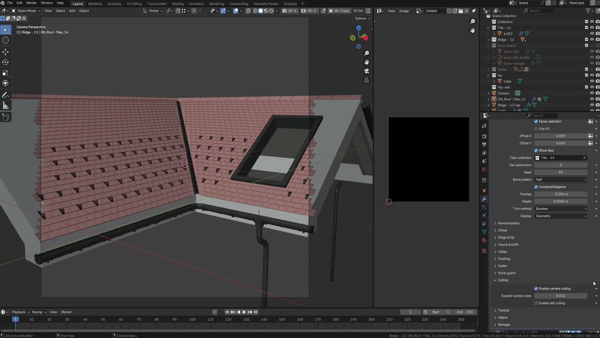
Drop a camera into the scene first and keep it out of the ridge collection so it isn't treated as a tile source. With the roof object selected, expand Culling on the Roof Generator and enable Camera Culling. Switch into the camera view to check the framing. If you notice gaps creeping in along the edges of the frame, widen the culling frustum slightly so the safety margin extends a little past what the camera actually sees.
Once you're happy with the framing, enable Self Culling on the same panel. The generator then hides every tile sitting on a face the camera can't see, which is the single biggest VRAM win you can get on a sprawling roof without changing any of the look settings.
If tiles you actually want in shot start disappearing, for example on a face that's only just clipped by the frustum, turn self culling back off rather than fighting it. It's a free optimisation when it works and the wrong tool when it doesn't.
Moss layer using height, AO and edge proximity
The built-in moss shader that grows from tile crevices, ambient occlusion and edges to push a clean roof toward photoreal in a single slider.
Adding moss in render preview
Tucked into the Roof Generator is a built-in moss layer that does the kind of work a material artist would normally bake by hand. Switch the viewport to render preview, toggle the moss on, and you immediately see growth settling into the crevices and gaps between tiles. Right where you'd expect it to land on a real roof.
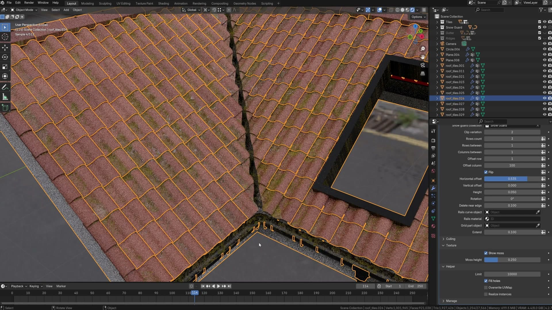
Two signals drive the placement. The first is height: the generator reads the profile of the tile so the parts most exposed to rain stay cleaner, while the sheltered low points pick up moss first. The second is ambient occlusion, which is baked into the same network and pushes the moss into edges and contact points before it spreads across open faces.
Some tile profiles read this effect better than others. A deep, sculpted tile with pronounced overlap lines will show the moss reading much more clearly than a flat, shallow profile, so it's worth swapping tile collections if the first one you try looks too subtle.
Density control via the moss slider
All of this is controlled from a single slider. Pull it up slowly and you'll see the moss build in stages rather than appearing all at once. The AO-driven crevices fill first, then the height-driven low points, then everything else.
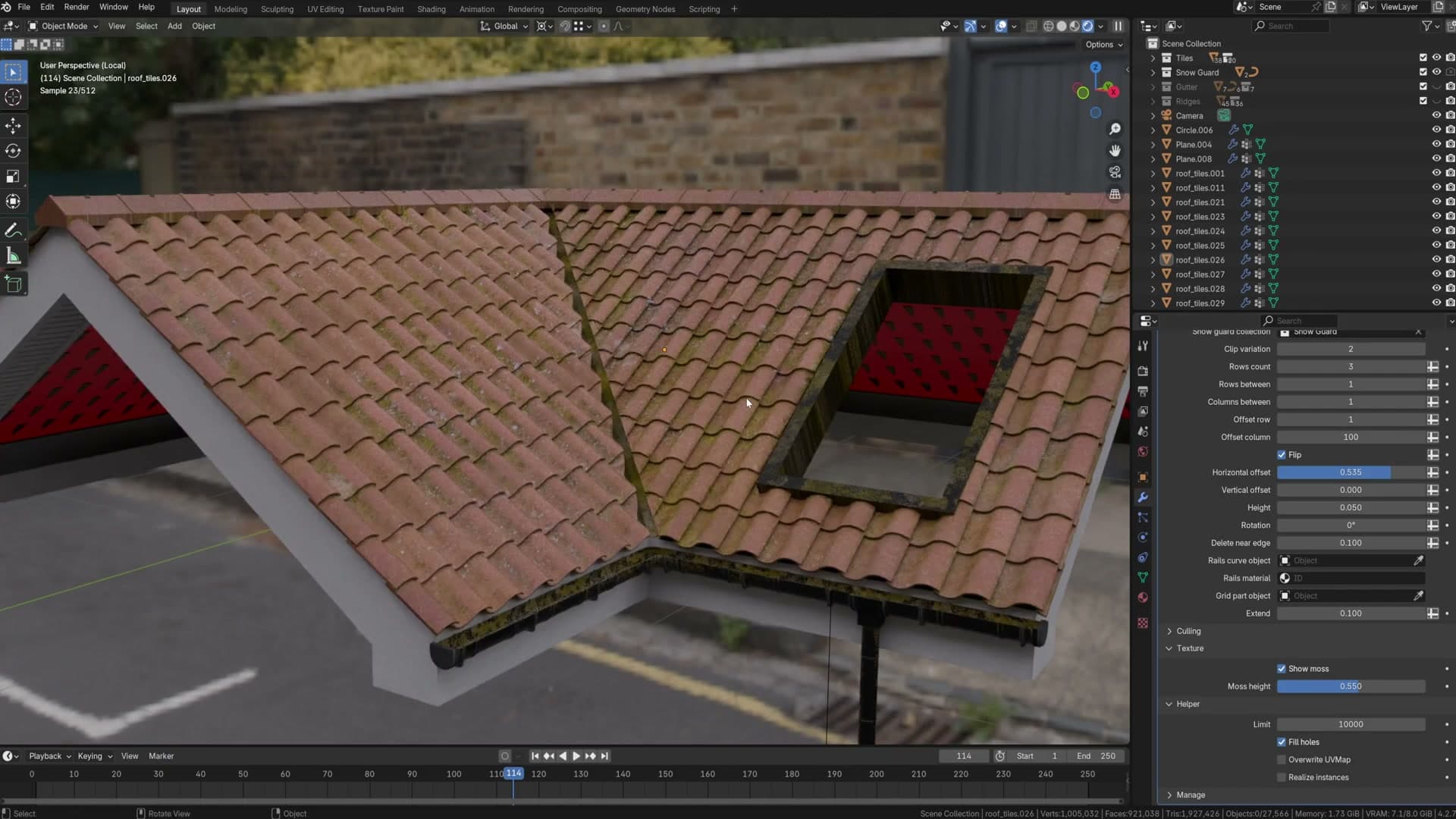
Around 0.15 the moss is barely there: a soft accent sitting in the deepest tile gaps and along edges that the ambient occlusion has caught. It reads as a clean roof with a hint of weathering, which is often all an exterior shot needs.
Push the slider up to roughly 0.55 and the roof crosses into properly weathered, photoreal territory. This already looks convincing on its own. Combine it with the position, rotation and scale randomisation from earlier modules and broken-up tile shapes catch the moss differently across the surface, removing any sense of a repeating pattern.
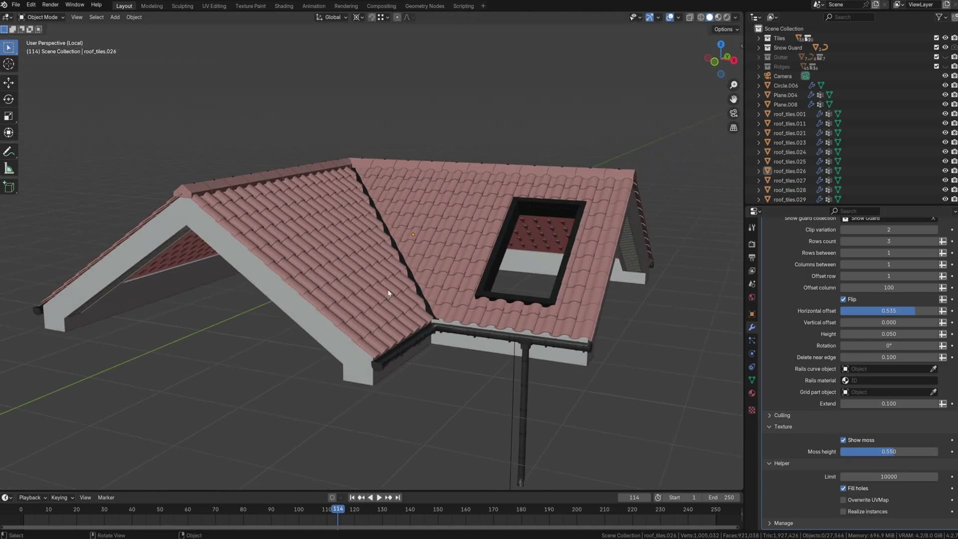
Moss is currently the only growth layer in the addon. A snow layer is planned and works on the same principle of building up over the surface, but it has been paused for this release. If you see references to snow in the UI, treat them as a preview of what's coming rather than a feature to rely on today.
Metal panel roofs: profiles, drip edge, dry verge and bolts
The second roof system in the generator, driven by profile curves instead of tile geometry. Covers profile creation, drip edge, dry verge, ridge geometry, snow guards and the bolt collection.
Building a profile curve collection
Metal panel roofs run on the same generator, but instead of scattering tile geometry across the surface they extrude profile curves along it. Select the panel object and you'll see a profile collection assigned. Every curve inside that collection is cycled evenly across the roof, so dropping more curves into the collection gives you more variation along the run.
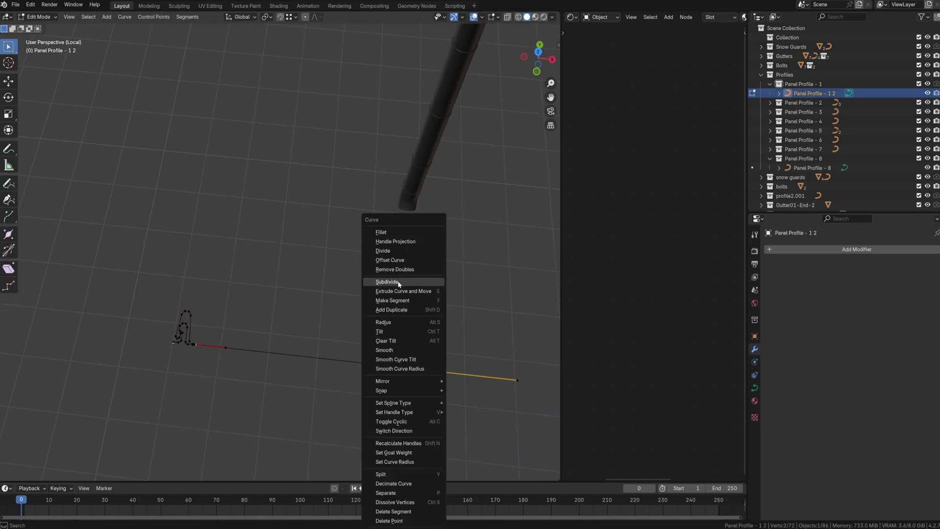
To build your own profile, drop a new curve into the collection, jump into edit mode and shape it however you like. Subdivide it a few times for finer control, then push points around until you have the corrugation, fluting or standing-seam shape you want. The shipped library already covers the most common cases (corrugated panels, flat sheets and copper-roof profiles), so you can either use those directly or treat them as a starting point.
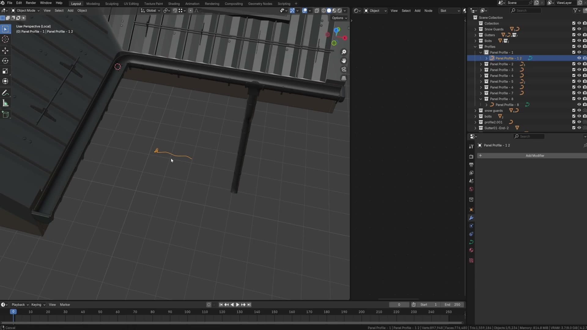
Two rules keep multiple profiles cycling cleanly. First, every curve in the collection must be the same length, otherwise they won't tile together along the roof. Second, the generator starts each profile from the same end point, so sliding a curve along its local axis shifts the whole run across the panel surface. Useful if you want to align seams, but it will throw things out if you move one curve and forget the others.
Drip edge and dry verge trims
Two trim parts run along the edges of a metal panel roof. The first is the drip edge, a folded strip of metal that runs across the bottom of the roof and bends down the front to throw water clear of the fascia. Turn the gutter off temporarily if you want a clean view of it. You can adjust the height directly so the drop matches the fascia depth and the trim sits flush against the edge below.
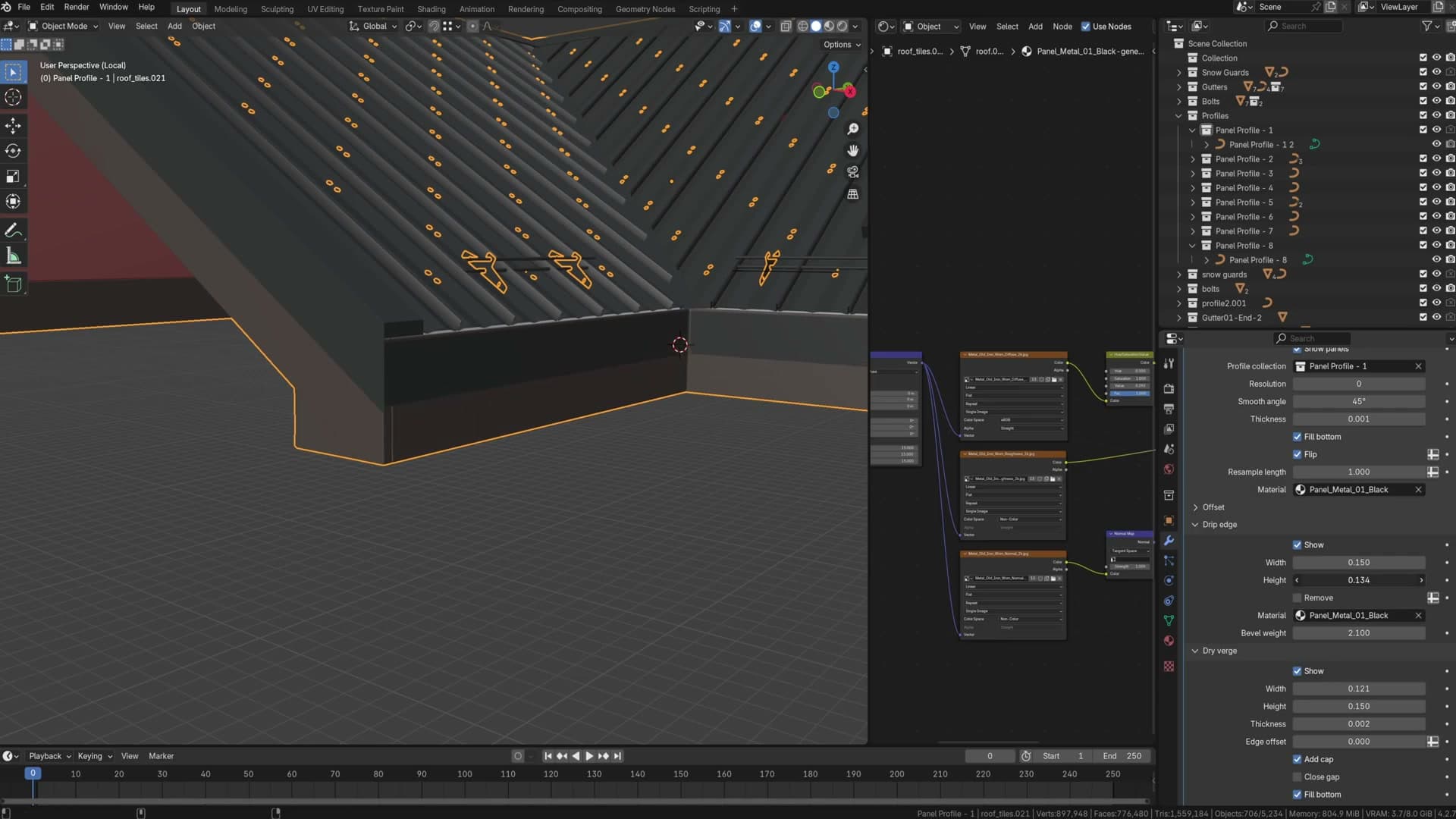
The second is the dry verge, which runs up the gable edge. You can add thickness and offset it to suit the panel profile you're using. Because metal panels are usually open on the underside, the dry verge ships with two cap modes: Add Cap leaves the end as it is, and Close Cap fills the geometry. Toggle Close Cap off and you'll see straight through the hollow end of the panel. Turn it on whenever the verge would otherwise reveal daylight under the trim.
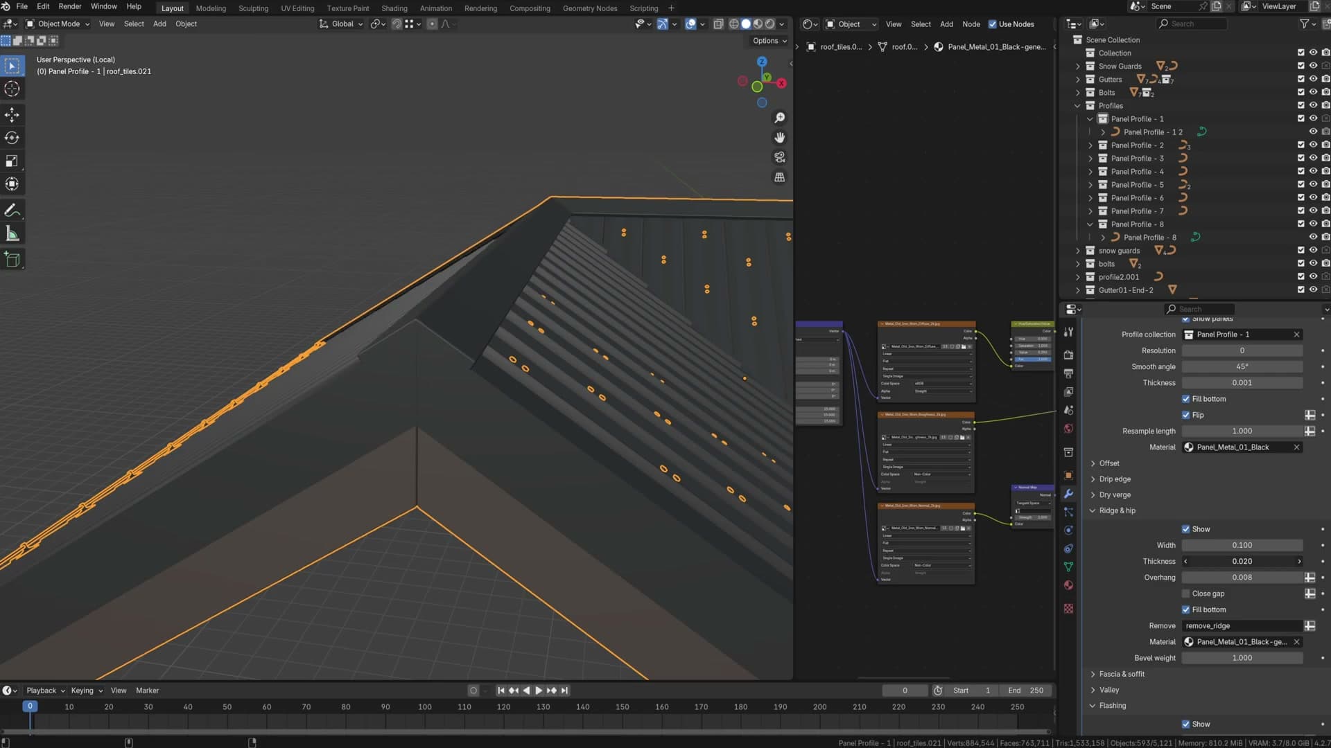
Metal hip, ridge and closed end caps
Hip and ridge on a metal panel roof are simpler than their tiled equivalents. They're just folded strips of metal rather than a collection of capping tiles. You get the usual handful of controls: width, thickness and overhang, any of which can be bound to attributes if you want per-edge variation across the roof.
The catch with profile-driven panels is that the cross-section can leave a visible gap directly underneath the ridge or hip cap, because the trim sits over the highest point of the profile while the troughs run away on either side. Toggle the close-off option on and the generator fills that gap so you don't see through the ridge from below.
Fascia, soffit, valley, flashing, gutter and snow guard all reuse the same settings you configured for the tiled roof. Nothing about those parts changes for metal panels. If you've already set them up for one roof in your scene, the same parameters carry across.
Single and double bolt collections
Bolts sell the realism of a metal panel roof more than almost any other detail, so the generator ships two dedicated bolt collections you can scatter across the panel ridges.
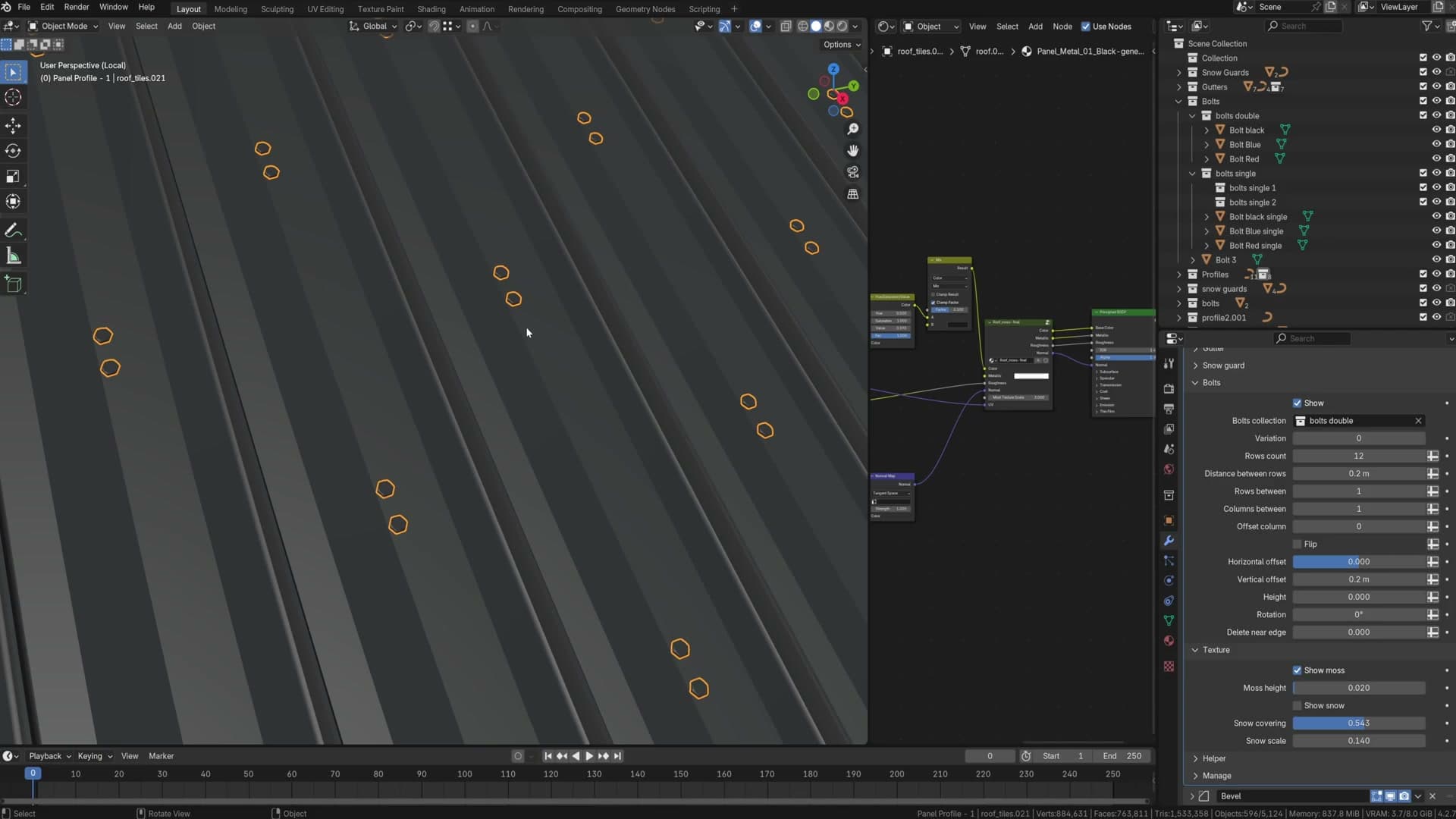
The two collections are single bolts and double bolts: single for narrow ridges, double for wider standing seams or anywhere two fixings sit side by side. Each collection holds several variations with slightly different colours and head shapes, and the generator picks between them at random so the bolts don't all look stamped from the same die. Drop in your own variants if you want different metals or weathering states.
To assign one, point the bolts slot on the panel object at whichever collection you want, then dial in four controls. Width sets how broad the strip of bolts is across each ridge. Reduce it too far and the bolts collapse to the edges, at which point you'll want to add extra rows. Frequency controls how often a bolt appears along the run, and distance controls the spacing between bolt heads.
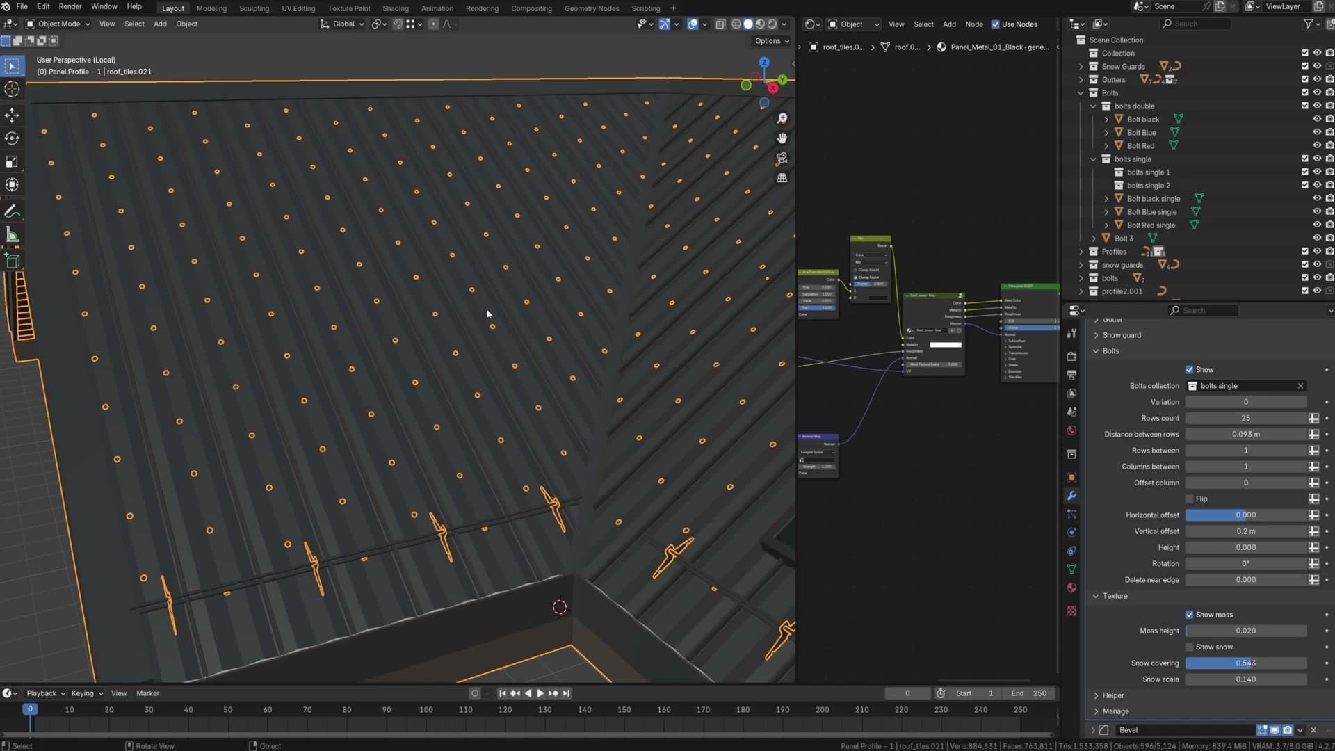
It's worth spending a moment on these. Photoreal metal panel roofs live and die on the small details, and a panel with no bolts tends to read as a flat shader trick the moment the camera gets near.
Panel-aware snow guards and moss
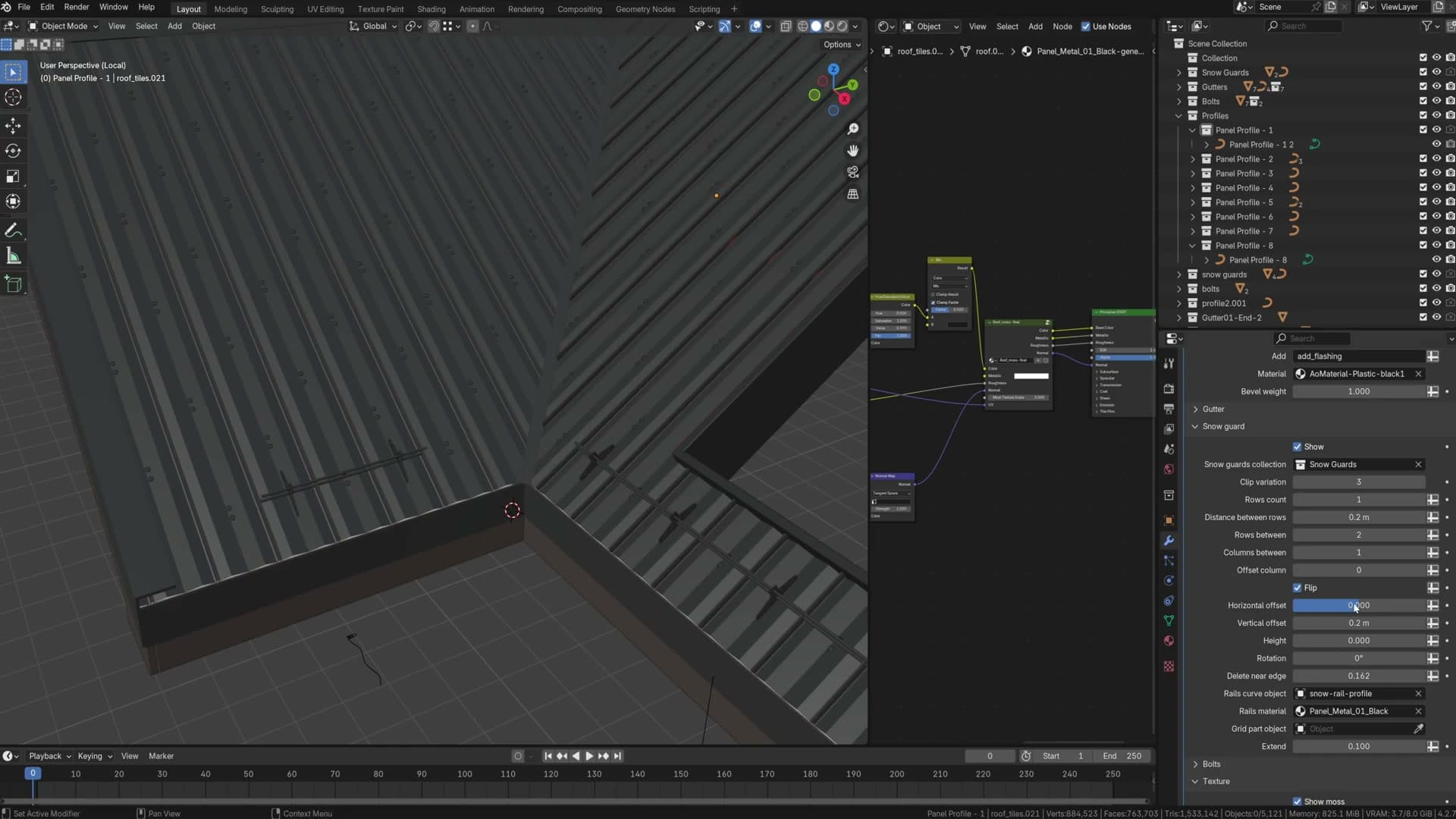
Snow guards on a metal panel roof are usually a continuous rail rather than the individual stops you'd find on tiled roofs, and the generator follows that convention. It uses the position of the first panel to offset the rail and then steps it across the roof, deliberately avoiding the panel ridges so each section of rail sits cleanly in the flat between profiles.
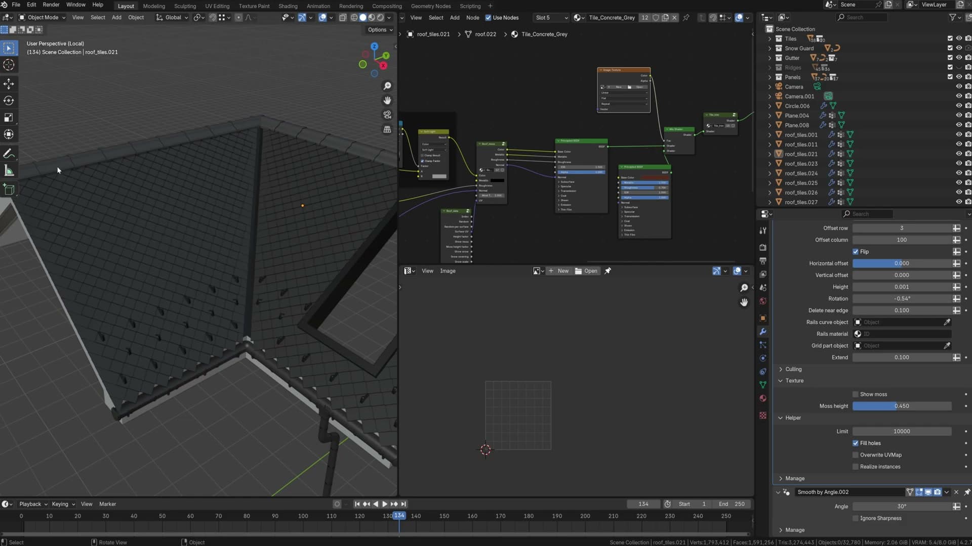
That avoidance is what causes the occasional missing section where you'd expect a rail. The generator has decided there isn't enough clear panel to fit one without crossing a ridge, and since the pipe would have nothing to attach to, it skips the segment. If you'd rather force a rail in anyway, turn off the Delete Near Edge attribute and the missing section reappears. Adjust the horizontal spacing or add extra rails if you want denser coverage across the run.
Moss layers onto a panel roof in exactly the same way as a tiled one. The same height, ambient occlusion and edge-proximity controls drive growth, and on a metal panel surface that reads as moss creeping into the troughs between profiles and around the bolt heads. It quietly does a lot of work to age a clean new roof.
Texture painting custom masks via Surface UV
Bypassing the per-tile UVs to paint masks across the entire roof surface: for moss, grime, colour blocks or any custom shader effect.
Overwrite UV Map and Realize Instances
The roof generator scatters instanced tiles, each with their own per-tile UVs. That is exactly what you want for tiling a clay or slate texture, but it is useless the moment you want to paint a freeform mask across the whole roof: moss along one ridge, a grime streak down one slope, or a colour block on a single section. For that, you need every tile to share one continuous UV space mapped to the entire roof surface.
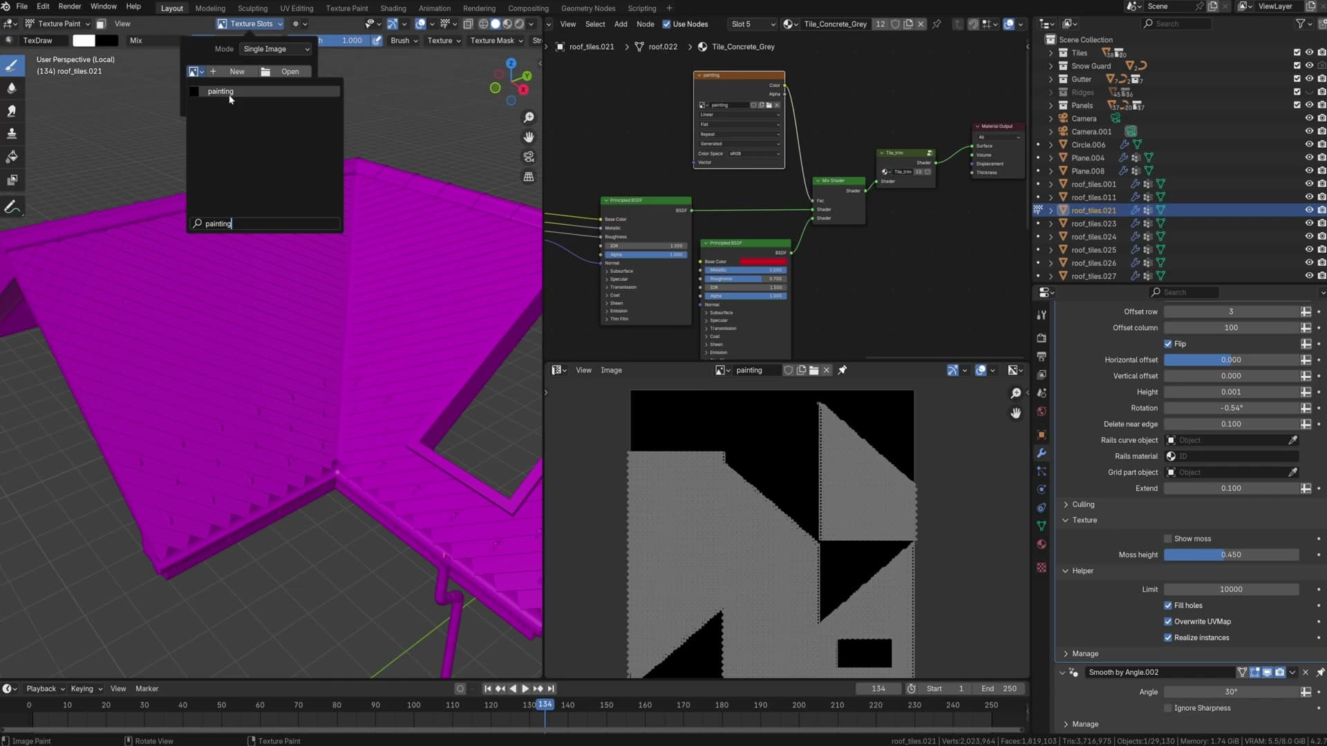
In the modifier panel, enable both Overwrite UV Map and Realize Instances. Overwriting the UV map collapses the per-tile coordinates onto a shared surface UV, and realising the instances converts the scattered instances into real geometry you can actually paint onto.
Treat both toggles as a temporary state. You only need them on while you set up and paint the mask. Once the texture is baked into an image, switch them back off so the roof returns to its lightweight, procedural form.
Painting the mask and wiring Surface UV into the shader
Switch into Blender's Texture Paint workspace. In the side panel, set the slot to Single Image rather than Material, then choose Painting. You should see the UV map unwrapped across the whole roof surface as one continuous canvas, not split into individual tile islands.
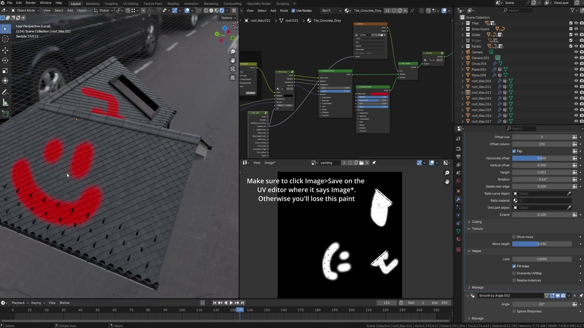
Now paint directly on the roof. Because the surface is unwrapped as a single piece, one brush stroke can sweep across multiple tiles. In the video I daub on a quick smiley face to show the principle, but the same approach lets you mask moss, grime, faded paint or any custom effect exactly where you want it. The more confident you are with texture painting, the more complex the masks you can build.
Once the mask is painted, drop back into object mode and turn Overwrite UV Map and Realize Instances back off. They were only needed to give you a single UV space and live geometry to paint onto. Leaving them enabled keeps the roof realised and throws away the procedural benefits.
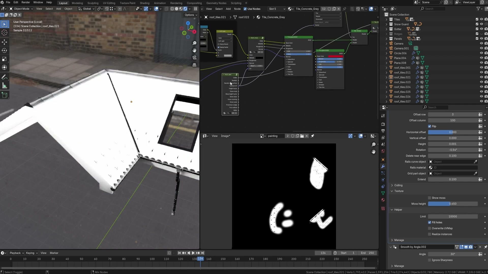
Open the roof's material node group and route the Surface UV input into the vector slot of the image texture that reads your painted mask. Surface UV refers to the whole roof as one continuous surface, not the individual tile UVs, so the mask reads back across the geometry in exactly the positions you painted.
Hit render and the painted mask appears across the tiles in the correct place: front, back and around every slope. If your roof uses several objects (ridge tiles, hip tiles, flashing), wire the same mask into their materials too so the painted effect flows continuously across the entire roof rather than stopping at the boundary of the main tile field.
Roof Data panel and applying the generator
Extra outputs from the geometry-node setup: random per surface, height factor, proximity to edge. And how to commit the whole thing to editable geometry when you need manual tweaks.
Roof Data outputs for advanced shading
Scroll further down the Roof Data panel and you'll find a stack of extra outputs the generator exposes for shading work. The snow-related outputs are greyed out in this release, but proximity to edge is live and ready to drive masks at the tile boundaries.
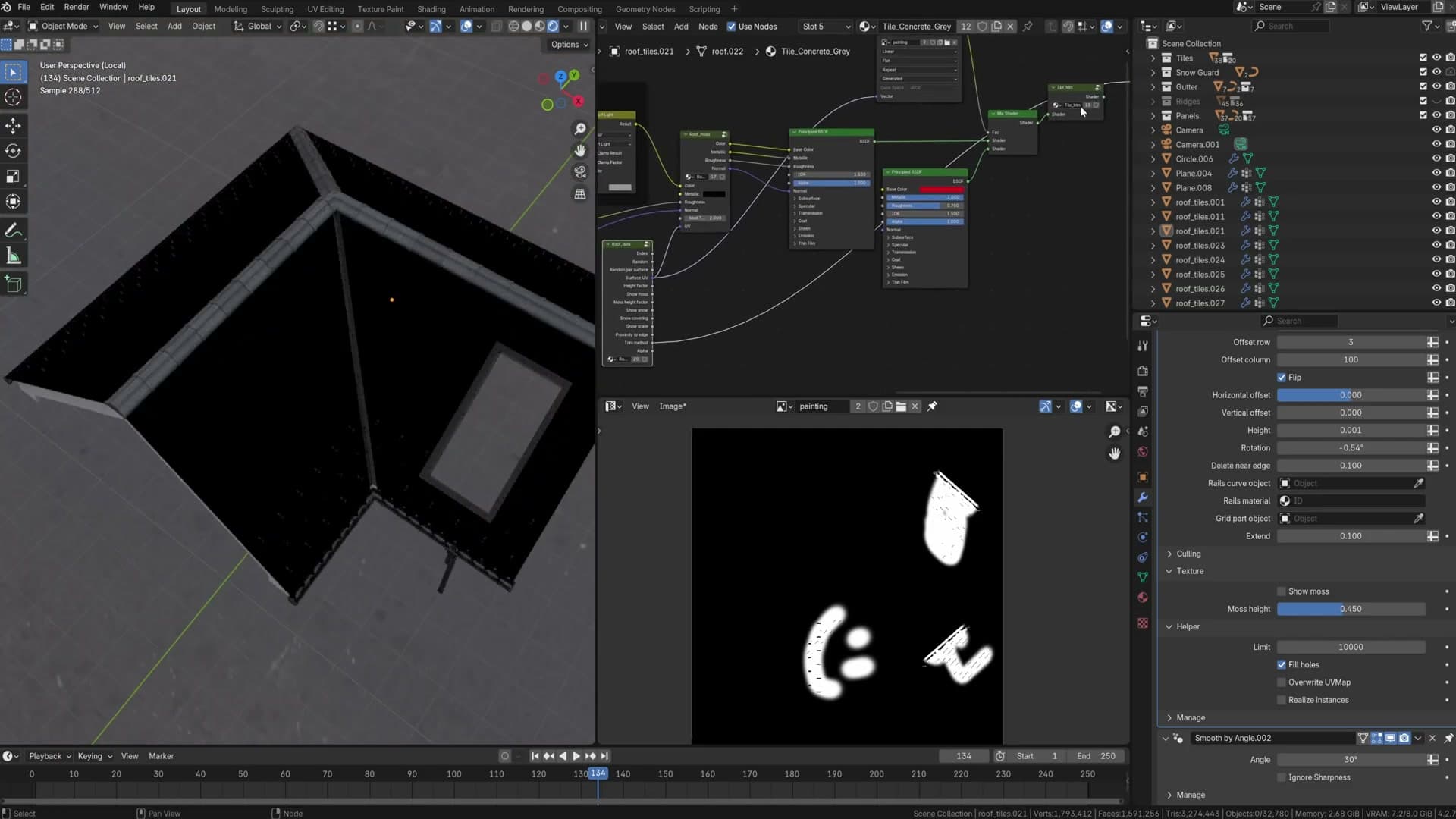
Below those sits the trim method output, which is wired up to feed the UVs used for the alpha trim, and the same applies to the matching output further down. These are the hooks you reach for when you want to push the look beyond what the main panel exposes, layering texture variation across the roof without touching the geometry.
Realize Instances + Apply for manual editing
Sooner or later you'll hit a spot where the generator can't quite get you what you want and you need to reach in by hand. For that, the Roof Data panel ships with a Realize Instances toggle that converts the instanced tiles into real, editable geometry the moment you apply the modifier stack.
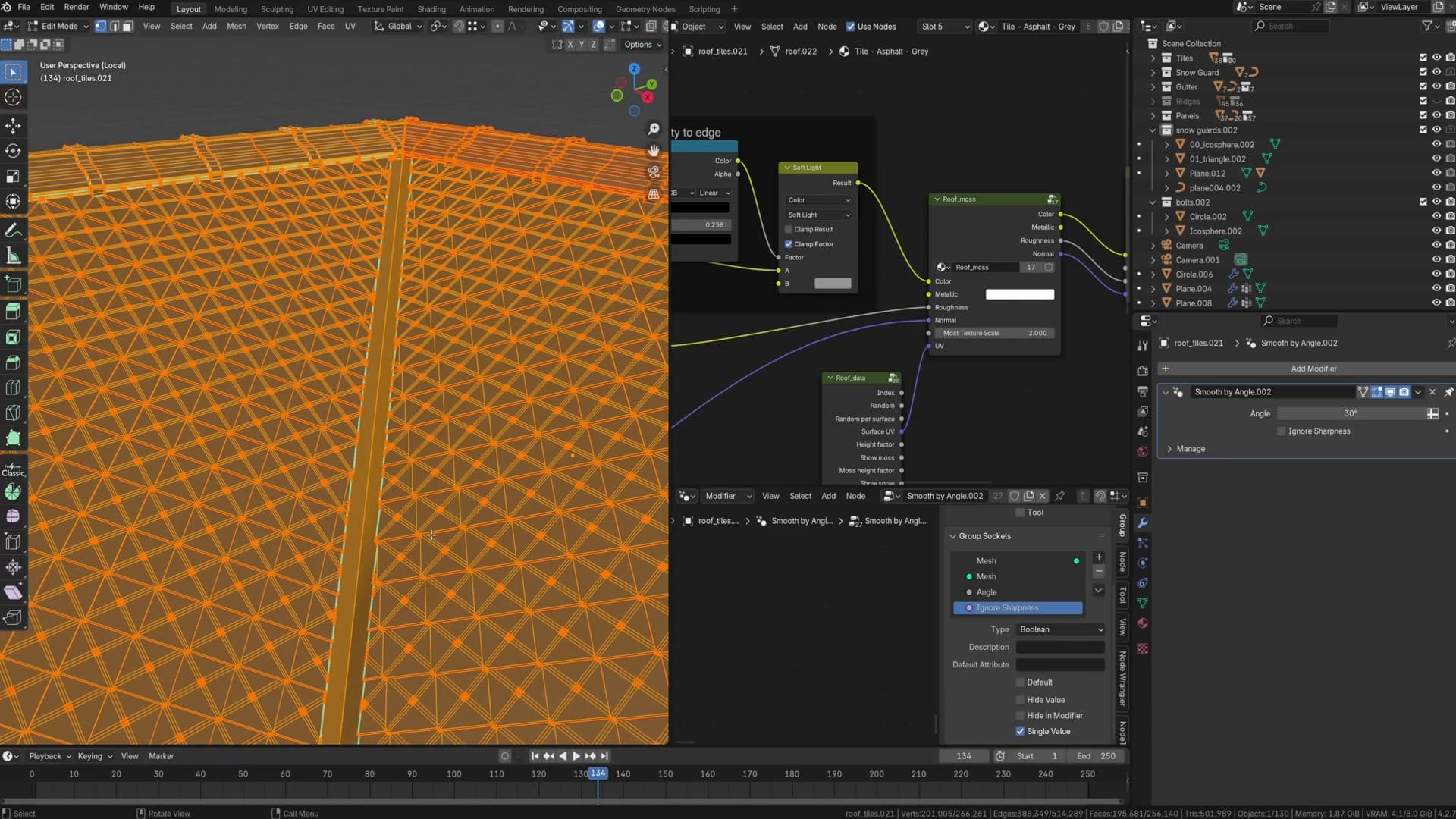
The workflow is two steps. First, enable Realize Instances in the Roof Data panel. Then apply the Geometry Nodes modifier, either from the modifier dropdown or by pressing Ctrl+A with the modifier focused. The whole roof bakes down into a single editable mesh you can tweak vertex by vertex.
The trade-off is VRAM. Once you realise, every tile counts as real geometry rather than a lightweight instance, so the scene gets heavier. On the example roof shown here that's around 200,000 faces, not unreasonable for a finished asset, but worth knowing before you bake out something much larger.
And that's the Roof Generator end to end. If you run into a roof shape or configuration that doesn't quite behave, drop into the iMeshh Discord and let the team know. This is version one and the more edge cases that get reported, the faster they make it into a patch. Thanks for following along, and have fun building roofs.

Tools and credits
Everything mentioned in this tutorial, with links.
- Blender is the renderer this entire build runs in.
- iMeshh is the studio platform (project management, client review, asset library, invoicing). The asset library used in this tutorial is included with every iMeshh Pro plan.
- Poly Haven provides free CC0 textures and HDRIs.
Pillar guide: Modelling hub · Get the Roof Generator