Introduction to Geometry Nodes and preparing the scatter surface
Geometry Nodes is one of Blender's most powerful systems, and one of the easiest places to start is procedural grass. Before any nodes get added, you need a clean plane to scatter on, separated from the pot mesh you built earlier in the course.
What Geometry Nodes can do for grass scattering
Geometry Nodes is one of Blender's newer systems, but it's also one of its most powerful. Once you understand the basics, it opens up procedural workflows that would otherwise mean modelling every detail by hand or stacking modifier after modifier. Grass is a friendly place to start, because the problem is well-defined: you have a surface, and you want a lot of small, slightly varied bits of geometry spread across it.
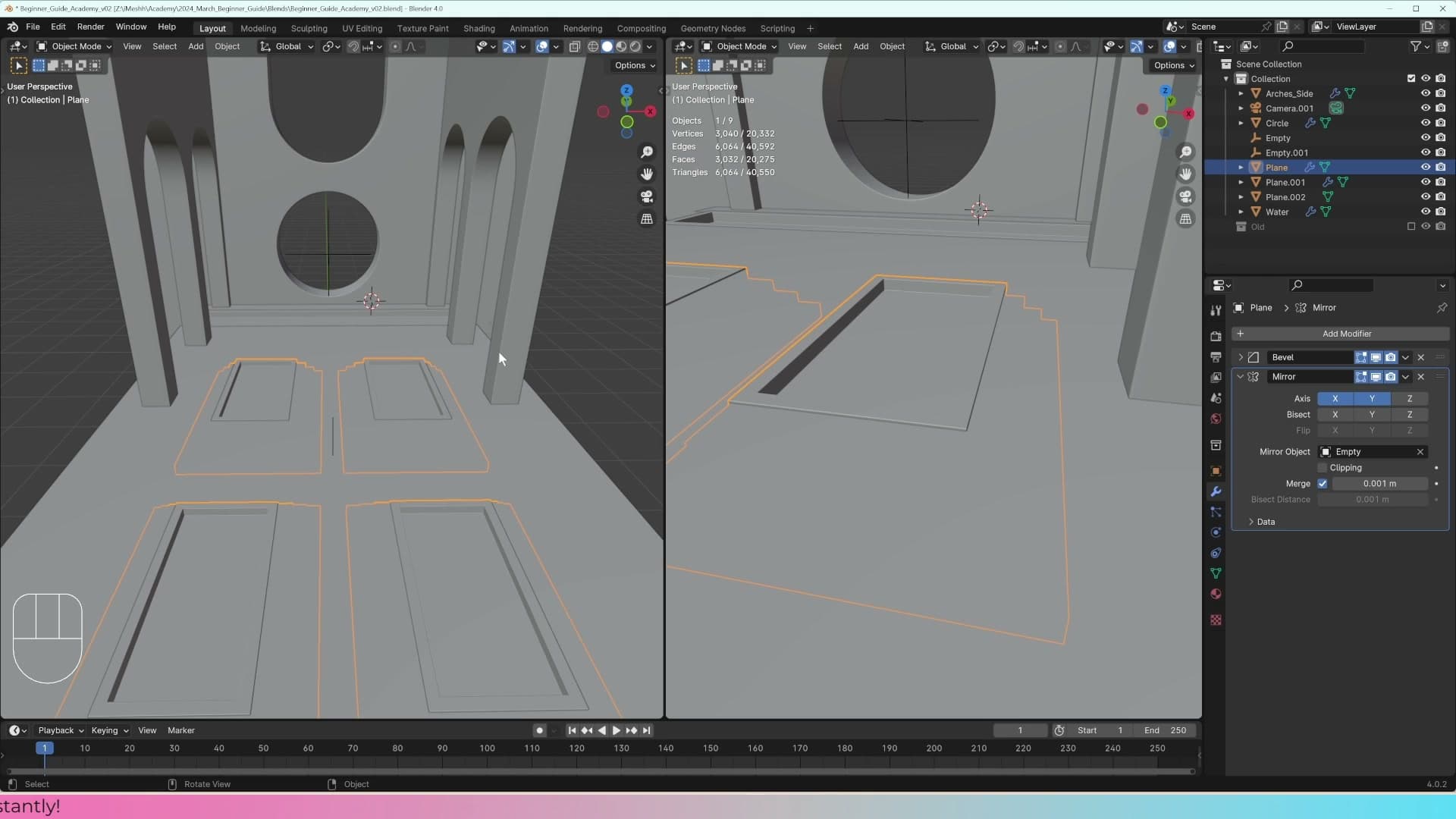
The goal for this part of the course is to fill the pots you built earlier with grass. You'll work on one pot first, get the scatter system behaving the way you want, then reuse the same setup across the others. By the end you'll have a clear picture of how a Geometry Nodes scatter graph fits together and where each node sits in the chain.
Separating a face from the pot to use as the scatter base
A Geometry Nodes scatter system needs a dedicated surface to spawn geometry on, so before any nodes get added you need to pull a clean plane out of the pot you already modelled. Select the pot, press Tab to drop into edit mode, then press 3 to switch to face select. Click the top face (the one you want grass to grow out of) to select it on its own.
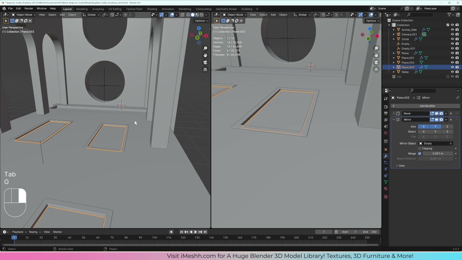
Press Shift+D to duplicate the face, then move it straight up along the Z-axis so it sits a short distance above the rim of the pot. Left-click to confirm the position. With the duplicated face still selected, press P and choose Selection to break it out into its own object.
Drop back to object mode, click the new plane to select it on its own, and delete any modifiers it inherited from the pot. You want a completely clean, unmodified surface as your scatter base. Anything still subdividing or arraying in the background will fight with the Geometry Nodes setup later. Switch into Local View so the plane sits alone in the viewport, with the rest of the scene hidden out of the way while you build the system.
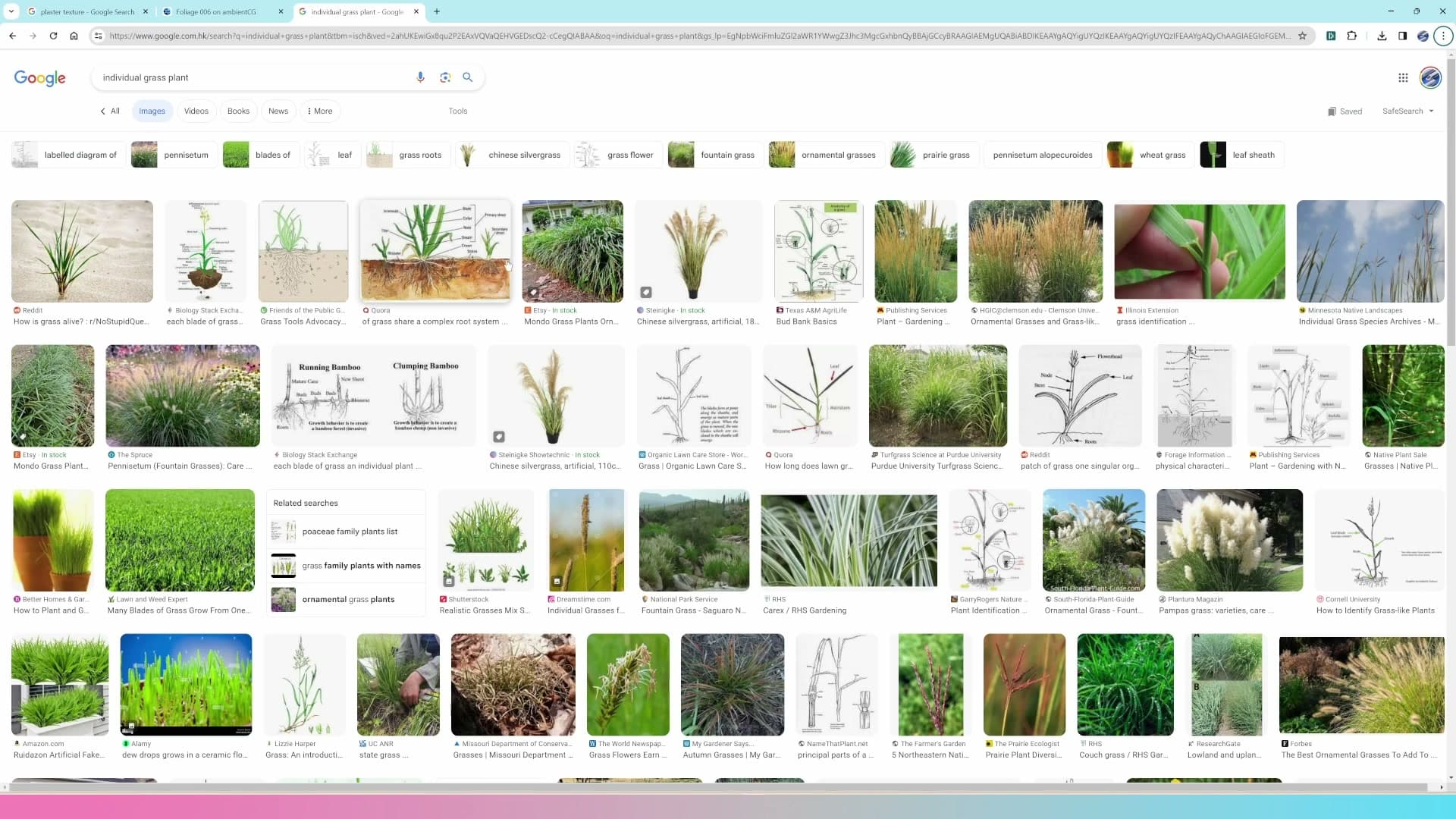
Before you start scattering anything, it's worth being deliberate about what you're going to scatter. A lot of the grass systems floating around online take a single blade of grass on a plane and dot thousands of copies of it over the ground. The result almost always reads as fake: too uniform, too thin, too obviously the same shape repeated. Real grass grows in clumps, so the plan here is to model a small bunch of blades first and scatter the clump. That gives you natural variation across the surface for free. A procedural setup that scatters clumps looks convincing; one that scatters single blades looks like a video game lawn.
Sourcing foliage textures and dropping in the reference image
Realistic grass needs real PBR maps. AmbientCG has dozens of foliage sets that include base colour, roughness, normal, displacement and (crucially) opacity maps. Drag the colour map into the front view so you can model the blades directly on top of it.
Downloading PBR grass maps from AmbientCG
Realistic grass starts with real PBR maps. The same way the plaster material earlier in the course leaned on a colour map plus a roughness and a normal, the grass shader needs a stack of textures pulling together. The easiest place to grab a complete set is AmbientCG, which has a sizeable foliage library with dozens of grass variants to choose from.
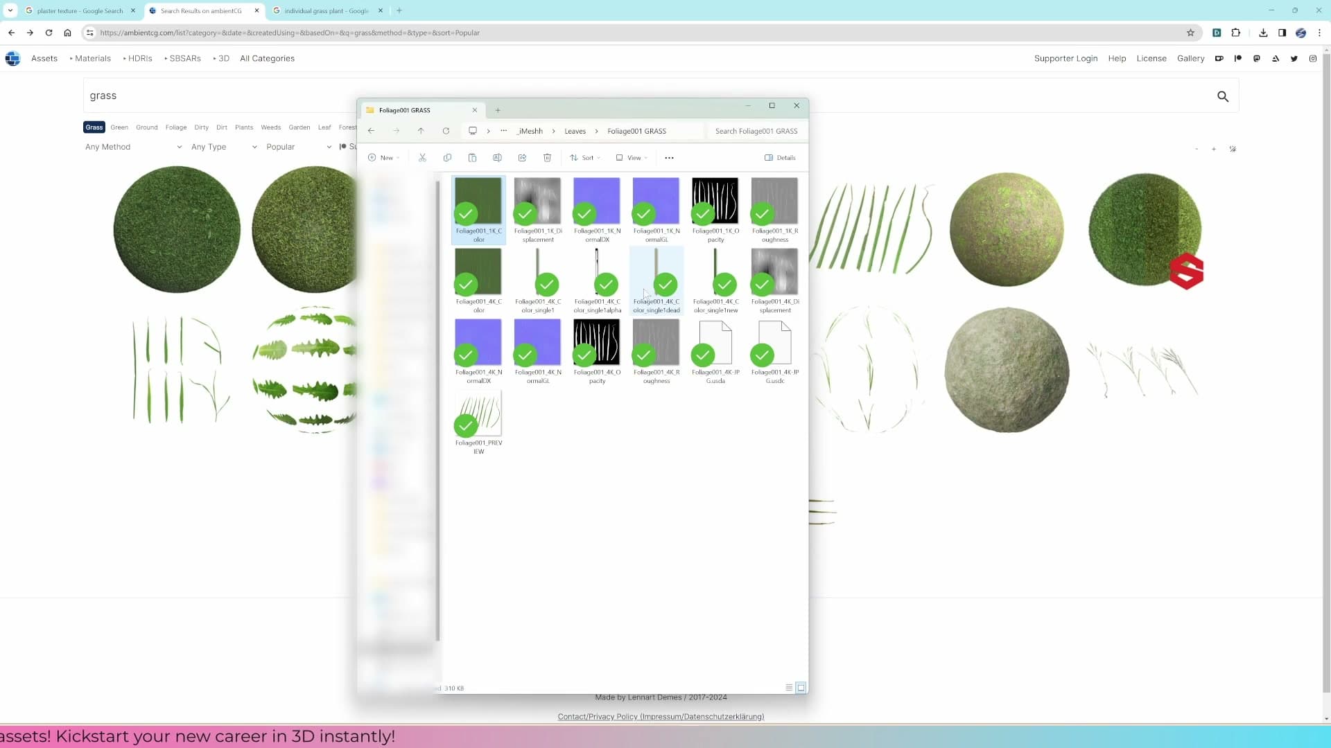
Pick a foliage set you like the look of and download the full pack. The one used here ships with everything the shader needs: a base colour, a displacement map, a normal map, a roughness map, and most importantly for grass: an opacity map. That alpha is what cuts the rectangular plane down into individual blade silhouettes later on.
The textures get you the look, but they do not get you the geometry. You still need to model the grass blades themselves inside Blender, with the colour map as your tracing guide.
Dragging the reference image into the front view
Switch to the front view first, then drag the grass colour map straight from your file browser into the viewport. Blender drops it in as a reference image, a flat plane that sits in your scene as a modelling guide.
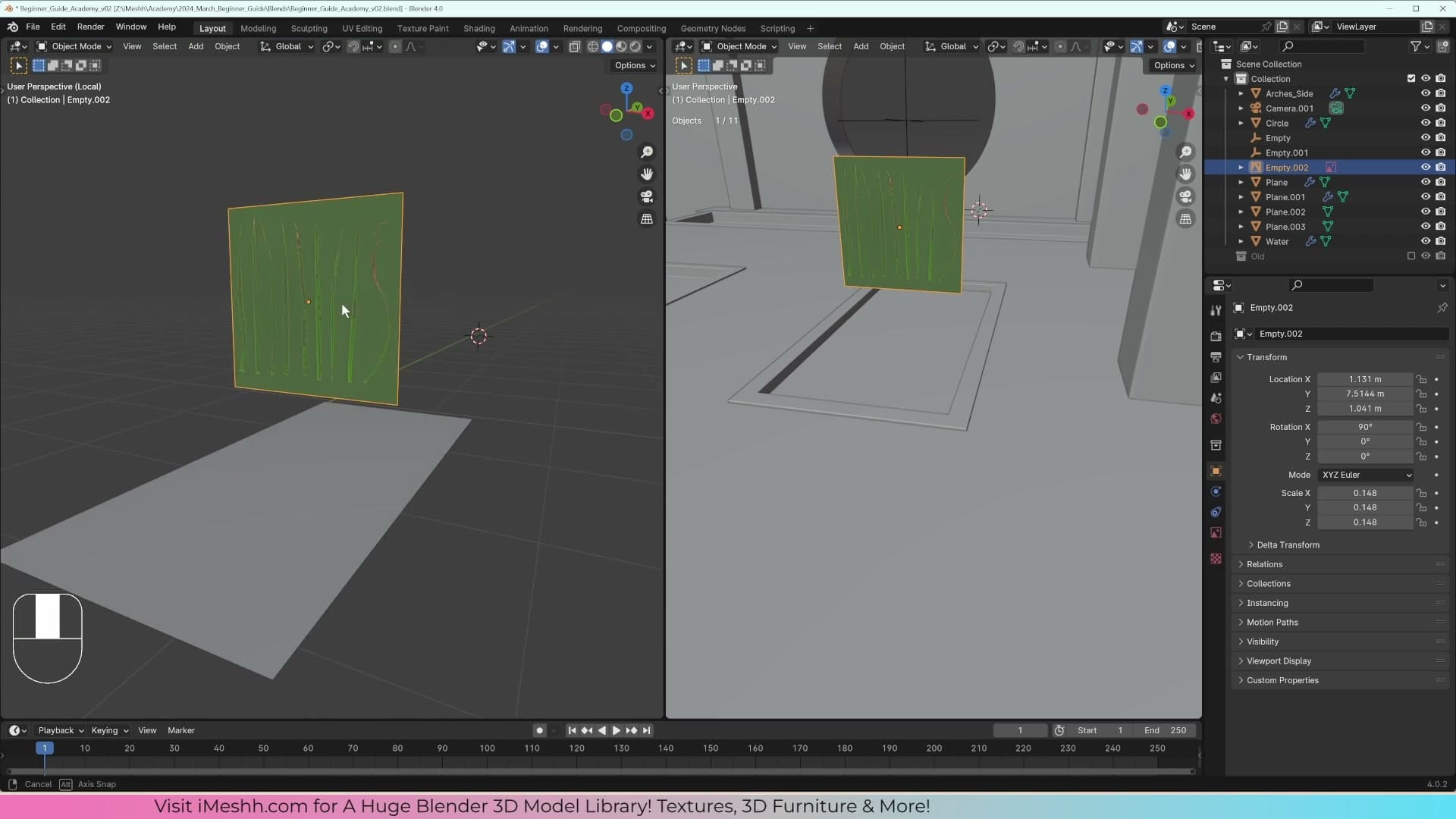
Reference images are invisible to the render, so there is no need to hide or delete it later. Toggle its visibility off and it disappears from the camera; toggle it back on and you have a perfect template to trace your blades over.
The order matters here. If you drag the image in from a perspective angle, the plane comes in tilted at a strange orientation and is awkward to model against. Always jump to the front view first, then drop the file in.
With the reference parked in the front view, you are ready to start cutting individual blades on top of it.
Modelling grass blades by tracing the reference
Each blade is a thin plane traced directly on top of the reference image. Keep the polycount low. These blades will eventually be instanced thousands of times, so heavy geometry will tank your viewport.
Tracing the first blade with extrudes
With the reference image dropped into the front view, pick the straightest blade in the photo to model first. It's the easiest shape to trace and gives you a clean base to duplicate later. Press Shift+A → Mesh → Plane to add a new plane, tab into edit mode, then scale it down, rotate it ninety degrees, and scale it in again until it roughly matches the width of the blade in the reference.
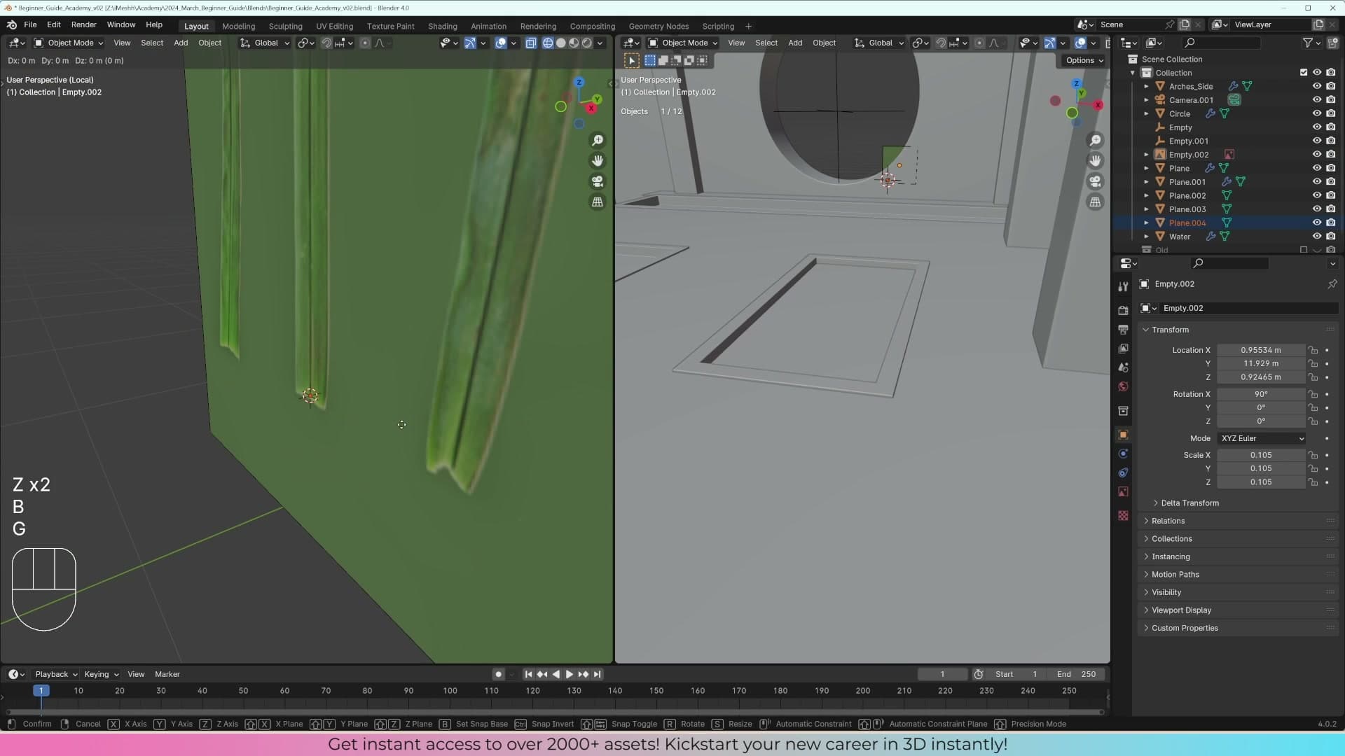
Trace the blade by selecting each vertex in turn (click to select, G to move) and dragging it on top of the photo. It doesn't need to be one hundred per cent accurate. To extend the blade along its length, press E to extrude, but keep the polycount deliberately low. These blades will eventually be instanced thousands of times across the ground, and dense geometry on every clump will tank the viewport.
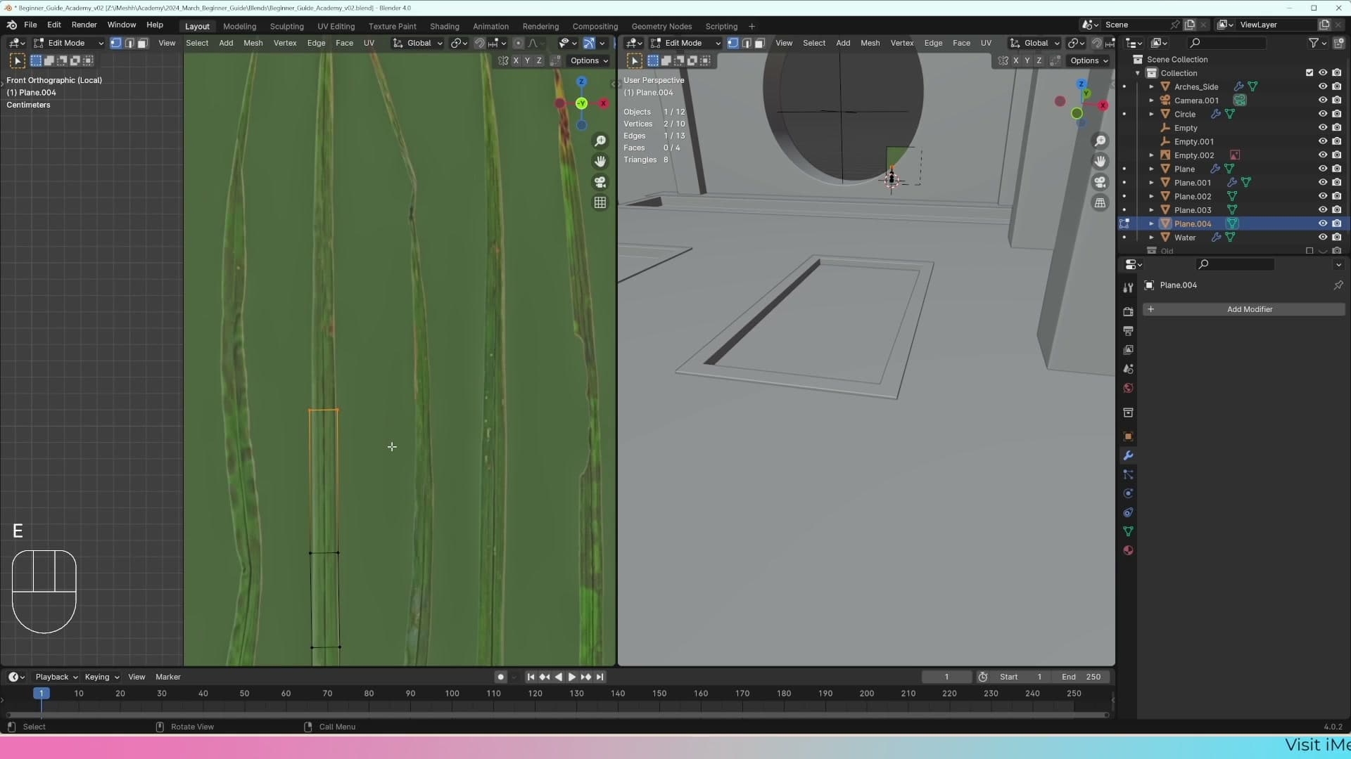
If a stray extrude leaves you with one segment too many, tidy it up with Dissolve Edges rather than Delete Edges. Dissolve removes the edge but keeps the surrounding vertices welded together; Delete would leave loose vertices behind for you to clean up by hand.
Duplicating and shaping the remaining four blades
Duplicate the finished blade with Shift+D, drop the copy to the side, then tab into edit mode and reshape it to follow the second blade in the reference. You'll probably need to add a bit more geometry (an extra extrude or two) to capture the curve, then nudge each vertex over the photo as before.
Repeat the duplicate-and-reshape pass for the remaining blades, aiming for five in total. Five gives you enough silhouette variety that no two clumps will look identical once they're scattered across the surface, without the source mesh becoming so dense that the viewport struggles. Don't worry about matching the reference pixel-perfectly; the goal is variation in shape, not photographic accuracy.
A more developed grass system already ships with the iMeshh platform, pre-built with significantly more blade variety and ready to drop straight into a scene. The version you're building here is a deliberately quick alternative, and it's the right project to learn the geometry-nodes scatter workflow on; the final result is still convincing enough for most archviz needs.
UV unwrap with Project from View
Because the blades were modelled directly on top of the texture in the front view, projecting their UVs from the same view gives a perfect 1:1 match with no manual UV nudging required.
Selecting the blades and projecting UVs from the front view
With the blades modelled, the next job is to give them the alpha texture you traced over. Tab back into Object Mode and select every grass blade you've built. The quickest way is a box select: press B, drag across the cluster, then hold Shift and drag again over the reference plane to deselect it. You only want the blades selected, not the textured backdrop they were traced on.
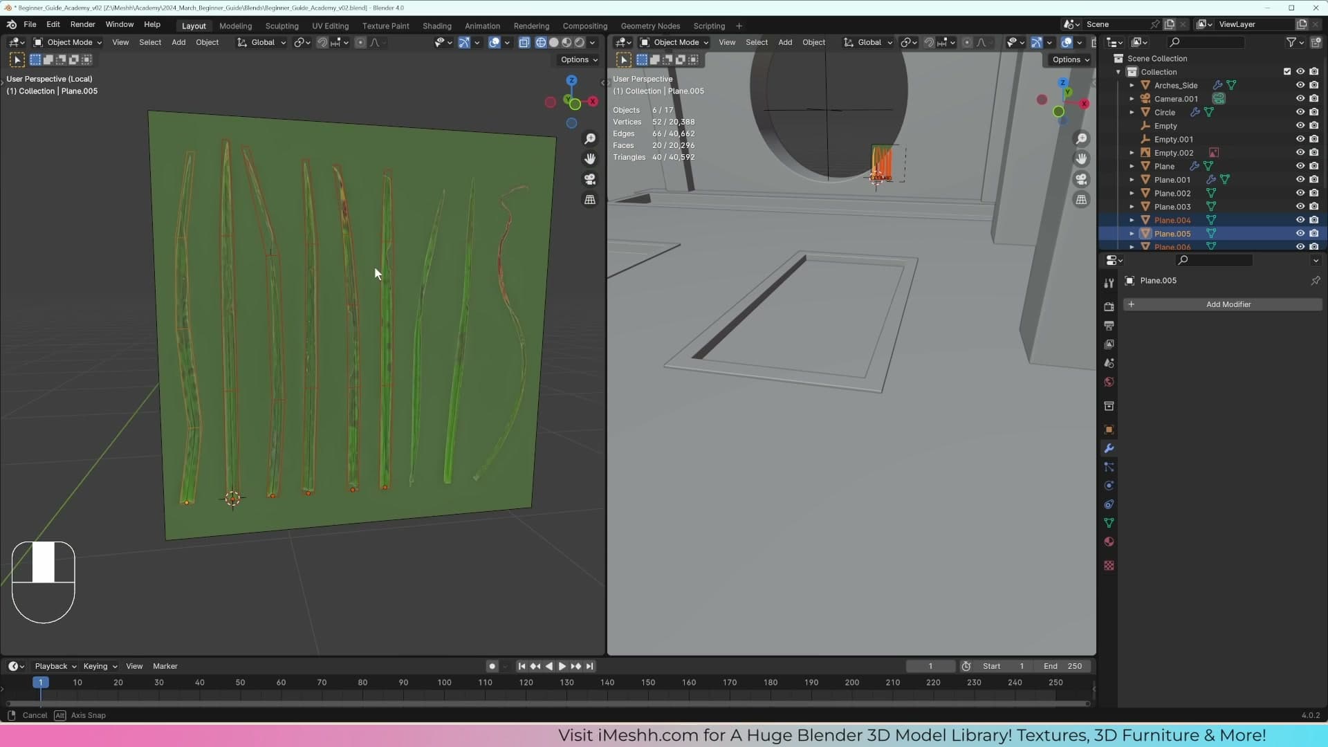
Press Tab to drop into Edit Mode on the combined selection, then hit A to select every vertex across all the blades.
Now run the unwrap. Press U and choose Project from View. Because your front view is already lined up exactly with the foliage texture, this projection bakes an exact copy of the blades' on-screen position straight into the UV layout. Open the UV editor and you'll see the unwrapped blades sitting in the same shape and arrangement they have in the 3D view, with no manual stitching and no seams to mark.
Aligning the projected UVs to the texture
With the UVs projected, load the foliage texture into the UV editor's image slot so you can see what you're aiming at. The projected UV island will land roughly in the right area but won't sit perfectly over the painted blades yet, so you'll need to nudge and scale it into place.
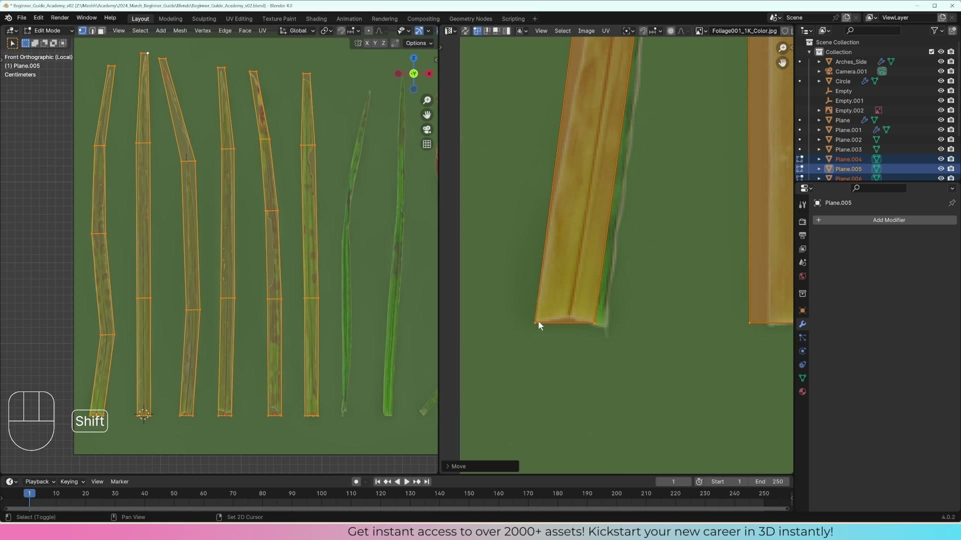
Drag the UV island over the matching cluster of blades in the texture so it lines up by eye. The shapes are already correct from the projection; you're only translating the island.
To scale the UVs cleanly onto the texture, you want the transform pivot anchored at a fixed point rather than the island's centre. Shift+Right-click in the UV editor at the spot you want to scale from to drop the 2D cursor at that location. Then open the pivot point dropdown and switch it to 2D Cursor.
Now press S and scale. The UVs will grow or shrink from the anchor you set, letting you size the island so it sits exactly over the painted grass blades in the texture.
Building the grass material with translucency
A flat textured plane reads as plastic. Real grass blades let sunlight pass through them. The way to fake that in Cycles is two stacked mix shaders: one for the alpha cutout, one for the translucent backlight, both sharing the same texture maps.
Wiring up base colour, normal, roughness and alpha
Switch the viewport to rendered shading and the blades vanish. The geometry is there, but Blender has nothing to draw on it because no material is attached. Open the Materials tab, click New, and rename the slot to grass.
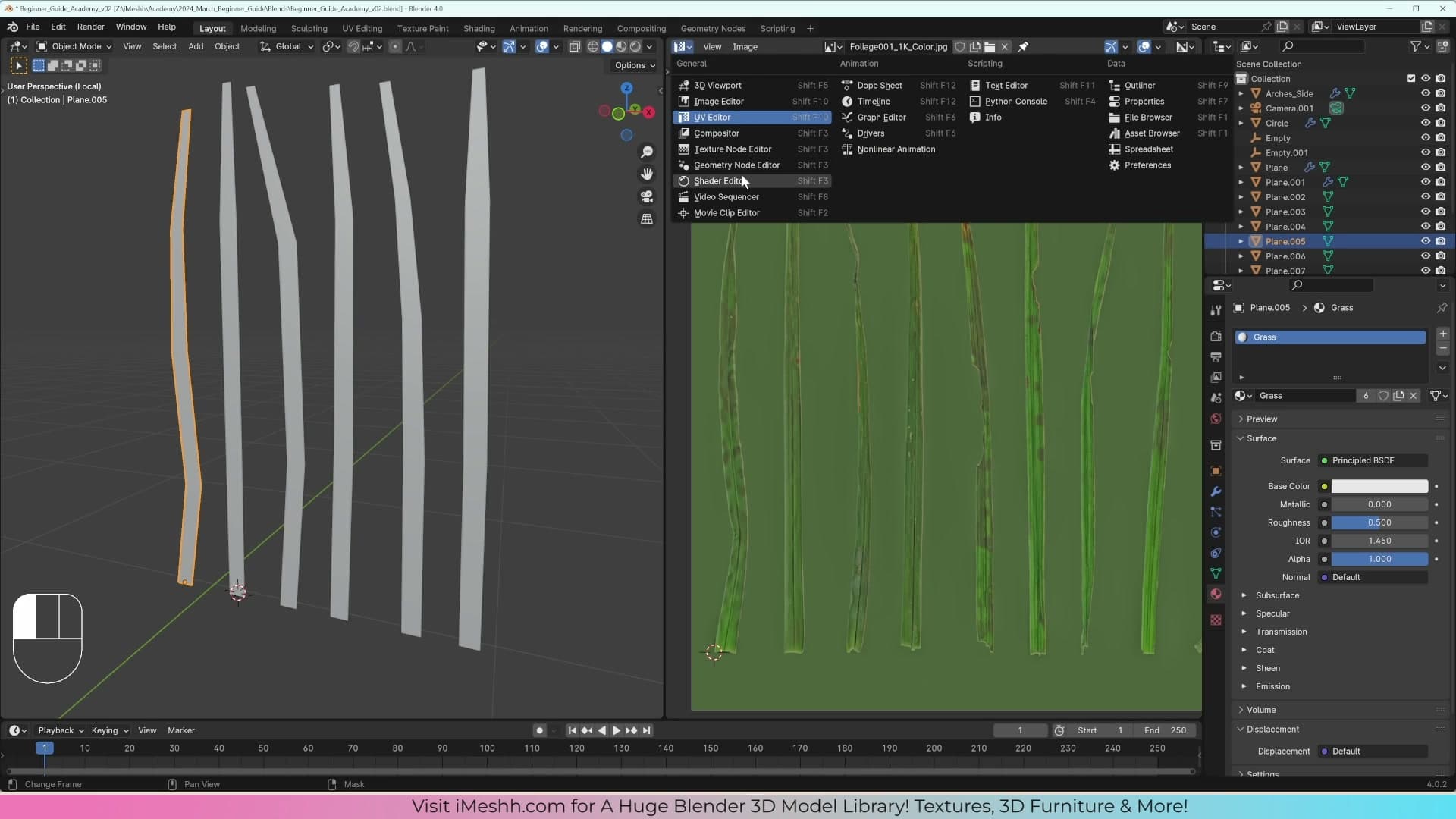
Only the active blade has the new material so far. Select every blade object in the scene, leave the one carrying the material active, press Ctrl+L, and choose Link Materials. All five blade objects now share the same shader slot, so any change to the grass material propagates across the clump in one place.
Open the Shader Editor and drop in the four PBR maps from the AmbientCG download. Wire the base colour into Base Color, the opacity map into Alpha, and the roughness map into Roughness. For the normal map, take the OpenGL variant, pipe it through a Vector → Normal Map node, and plug that into the BSDF's Normal input.
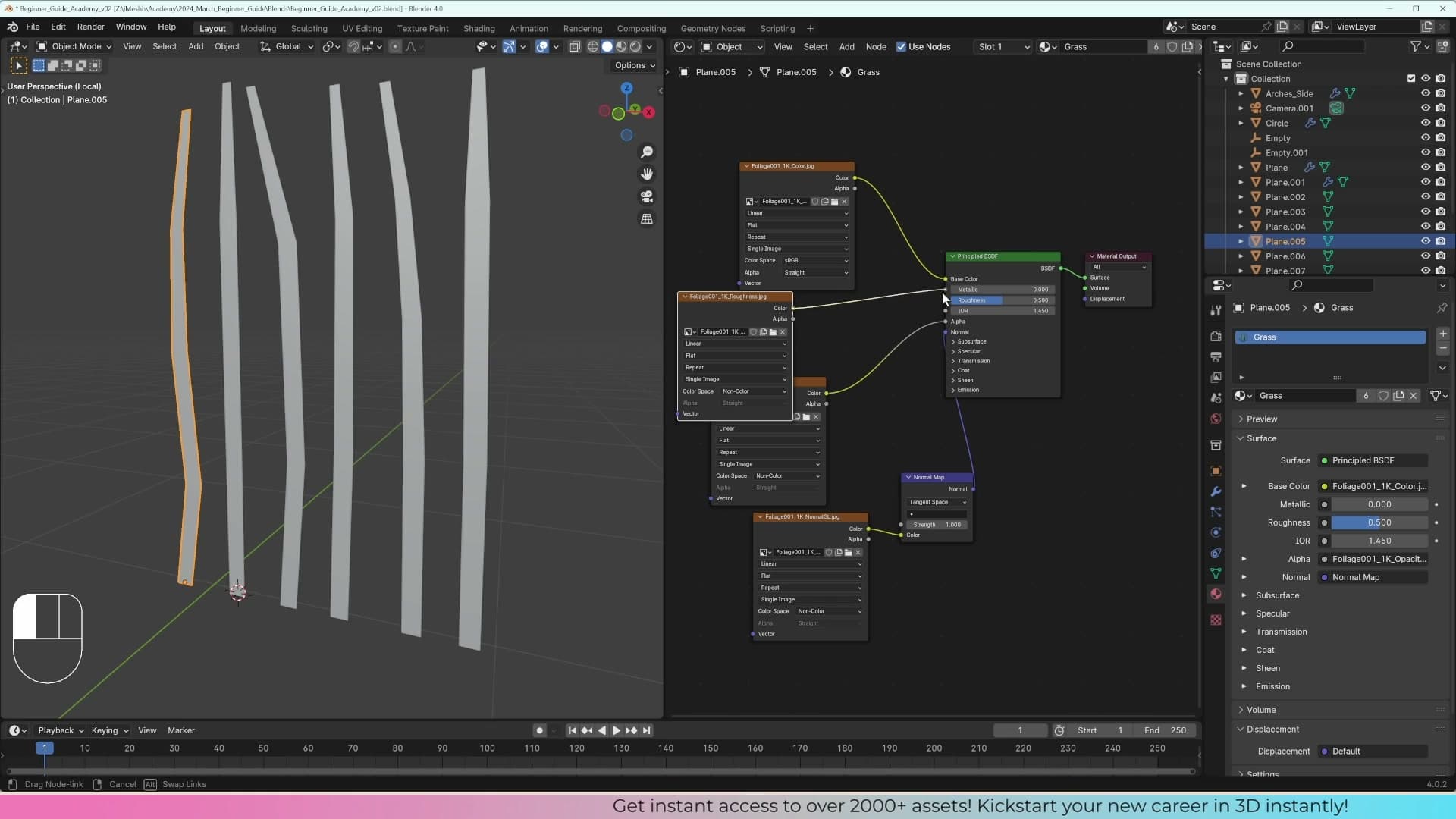
For every non-colour texture (opacity, roughness, and the normal map) switch the image node's colour space from sRGB to Non-Color. If you skip this, Blender treats the data as a photograph and gamma-corrects it, which throws the alpha edges and surface response off in ways that are hard to spot until they ship.
Flip the viewport to material preview and the planes already read as grass: green on the visible face, alpha-clipped to a clean blade silhouette around the edges.
Adding translucency for backlit blades
A flat PBR blade still reads as plastic. Hold a real piece of grass up to the sun and you can see warm light glowing through the leaf surface. That's translucency, and Cycles will fake it convincingly if you stack a Translucent BSDF underneath the Principled.
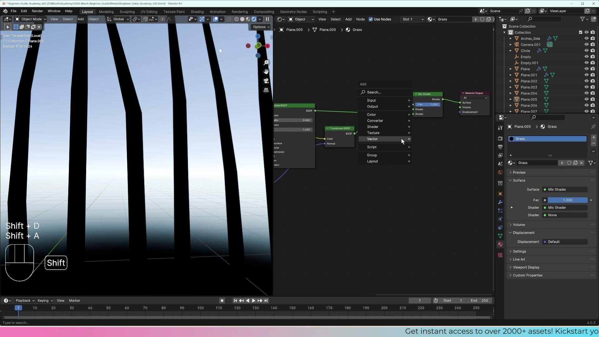
Press Shift+A and add a Mix Shader, plug its output into the Material Output, and slot the existing Principled BSDF into the first shader input. Then Shift+A again, add a Translucent BSDF, and connect it to the second input.
Feed the same base colour texture into the Translucent BSDF's Color socket, and the same normal map into its Normal socket. You want both shaders sharing the same maps so the blade looks consistent whether the camera is seeing the front face lit directly or the back face glowing with transmitted light.
Spin the view so the sun is behind a blade and you'll see daylight bleeding through the leaf, exactly the effect from the reference. One problem, though: the alpha cutout has stopped working. The space between blades that used to be cleanly transparent now reads as a solid green smear.
Fixing the alpha leak with a transparent mix shader
The reason the alpha leak appears is that the Translucent BSDF doesn't read the opacity map on its own. The Mix Shader is blending a Principled (which respects alpha) with a Translucent (which ignores it), and the translucent half is filling in the gaps that should be cut away.
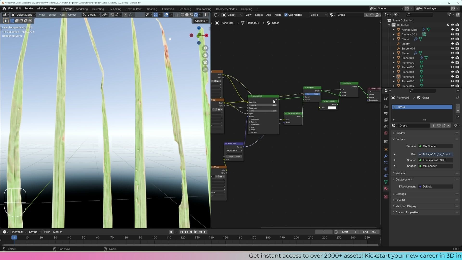
The fix is a second Mix Shader that handles transparency separately. Add a fresh Mix Shader along with a Transparent BSDF, and plug the opacity map's colour output into the new Mix Shader's Fac socket.
The factor wiring is the wrong way round by default. A Mix Shader reads its factor as "black uses the first shader, white uses the second", so with Transparent sitting in the top slot, every white pixel of the alpha map would make the blade invisible, which is the opposite of what you want. Swap the two shader inputs so Transparent sits in the slot that activates on black, and the cutout snaps back into place.
Now hand the Translucent BSDF its Color and Normal connections back, then route the output of this new alpha-cutout mix into the second slot of the original translucency mix. The finished graph has two stacked Mix Shaders sharing the same four texture maps: one cuts the alpha for transparency, the other layers translucency on top. It looks fiddly the first time you wire it, but the pattern is the same for any backlit foliage shader you'll build later: leaves, ferns, hedges.
Bending blades and assembling grass clumps
A flat fan of blades doesn't look like grass. Press O for proportional editing, bend each blade into a natural arc, then duplicate, rotate and scale to build three distinct clumps for the scatter system to pick from at random.
Bending blades with proportional editing
A flat fan of upright blades still reads as a flat fan, not as grass. To fix that you need to put a gentle curve in each blade so the tips arc away from the base. Drop into edit mode, swing the viewport round to a side view, and select the upper vertices of one blade.
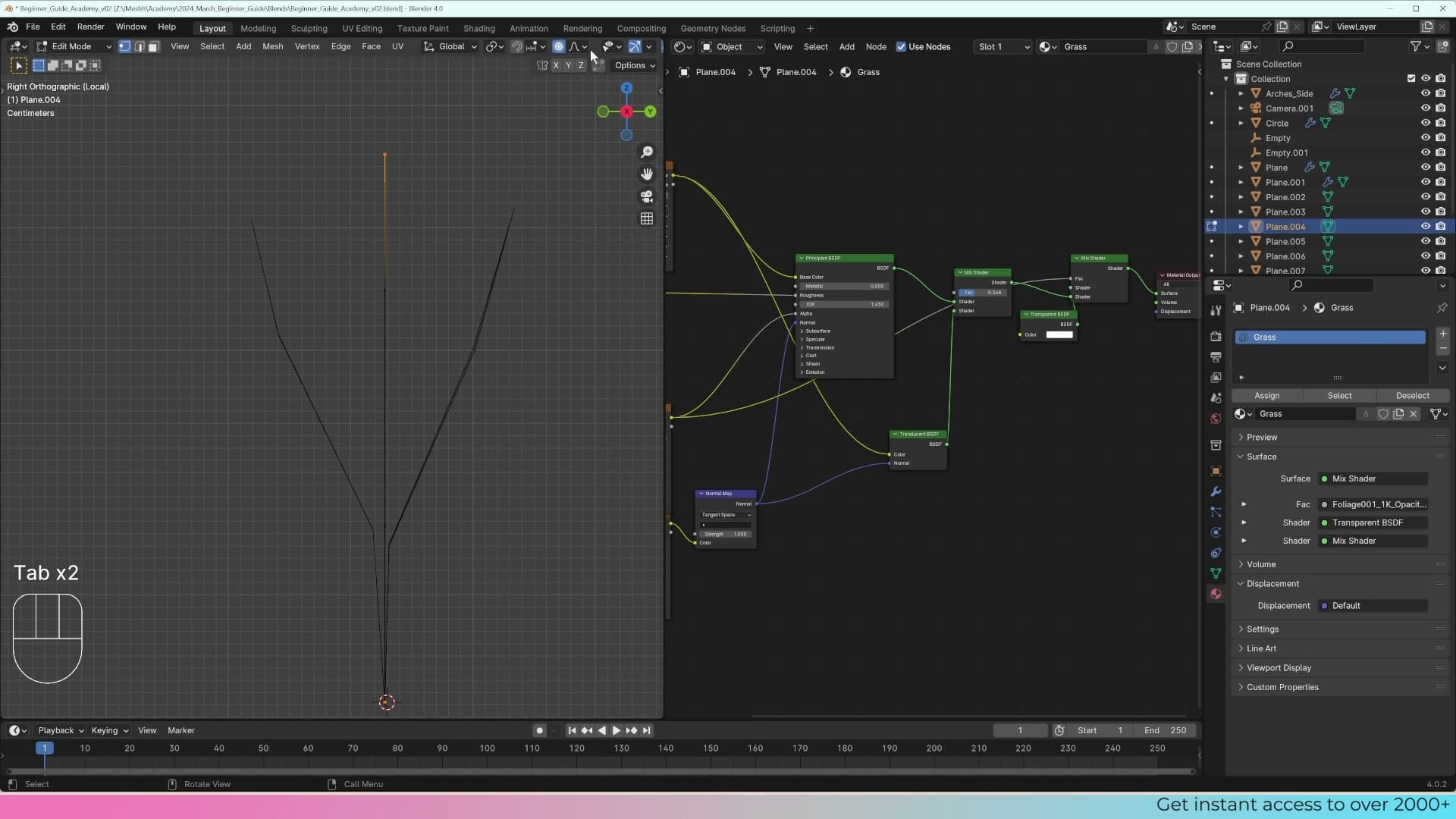
Press O to enable proportional editing. Now when you grab those tip vertices and drag them sideways, the neighbouring vertices further down the blade follow along with a soft falloff, producing a smooth arc instead of a sharp kink at the selection.
Scrub the middle mouse wheel while you're still in the move operation to resize the circle of influence on screen. A wider circle drags more of the blade along; a narrower one bends only the very top. Visualising the circle is the whole reason proportional editing beats trying to nudge each vertex by hand.
Work through every blade in the fan. Vary the falloff curve in the header dropdown between Smooth and Sharp so the blades don't all bend with the same profile, and pull some sideways as well as forward so the clump doesn't flop in a single direction. The more time you spend here, the more natural the eventual scatter will look. Every grass tuft in the final render is just a copy of one of these three clumps.
Duplicating and rotating clumps for variety
With one set of blades bent, pull their bases close together in the centre so the fan reads as a single tuft rising from one spot rather than a row of blades on a line.
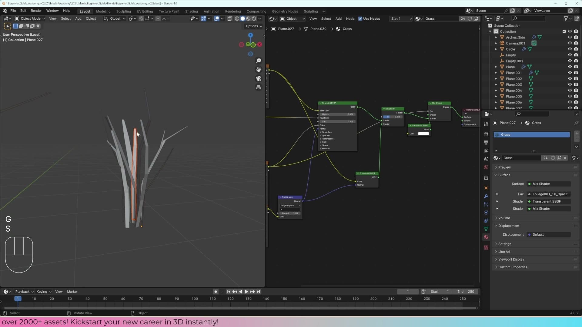
Select everything in the tuft, press Shift+D to duplicate, then R to rotate the copy and S to scale it. Drop it next to the original. You've just produced a second tuft from the same base blades. It looks different because the rotation and scale change which silhouettes face the camera.
If any blades from the duplicated clump are now poking through the original, nudge them sideways and give them breathing room. A clump where every blade clips into another blade looks worse than a sparser, cleaner one.
Repeat the duplicate, rotate and scale routine once more to make a third clump, then scale it on the Z axis to push the height up or down. By the end you want three visibly distinct tufts of different sizes: that's what the scatter system will pick from at random when you build the Geometry Nodes graph.
Joining clumps and moving them into a Grass collection
Each clump is still made up of many separate blade objects. Geometry Nodes scatters one object per instance point, so you need to merge each clump into a single mesh before it can be used.
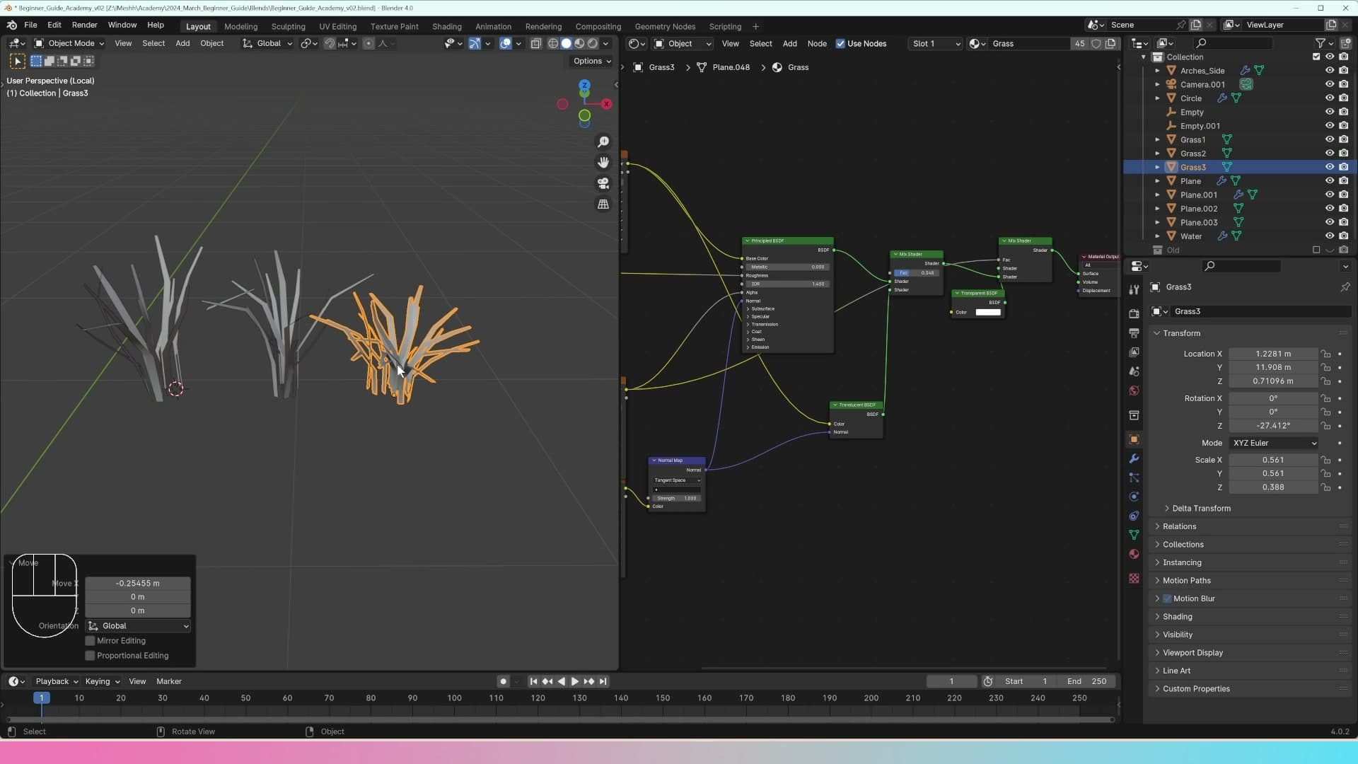
Box-select all the blades belonging to the first clump. One of them must be the active object (its outline will be a brighter shade than the rest). Press Ctrl+J and the rest get joined into the active one. Work through each of the three clumps in turn.
With all three joined, select them together and right-click → Shade Smooth so the blade surfaces read as soft rather than faceted. Then rename them in the outliner: grass1, grass2 and grass3.
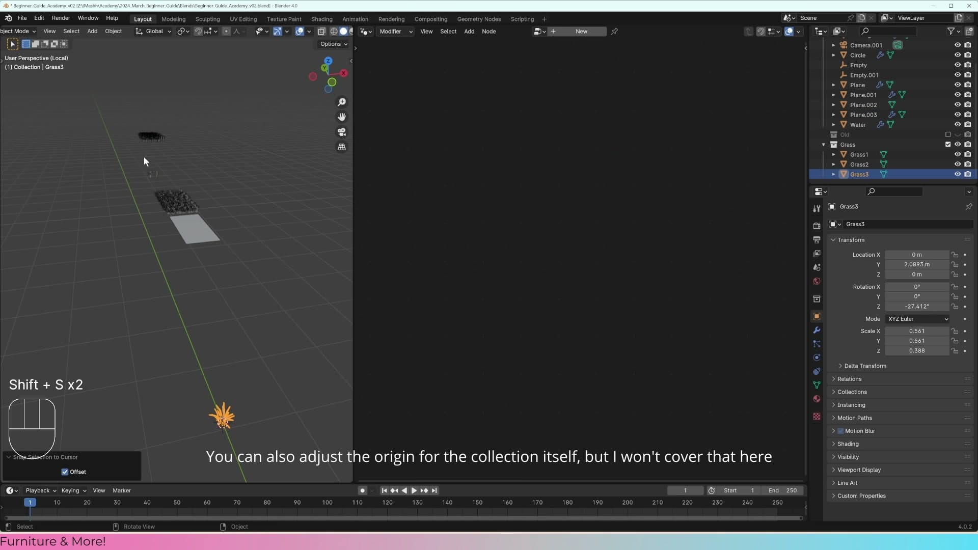
Recentre each origin. After all the duplication and dragging, the object origin probably isn't sitting under the clump any more. For each one, drop into edit mode, press A to select all the geometry, and slide the mesh so the base of the clump aligns with the origin point. Geometry Nodes places instances at the origin, so a misaligned origin shows up later as grass floating above the ground or sunk beneath it.
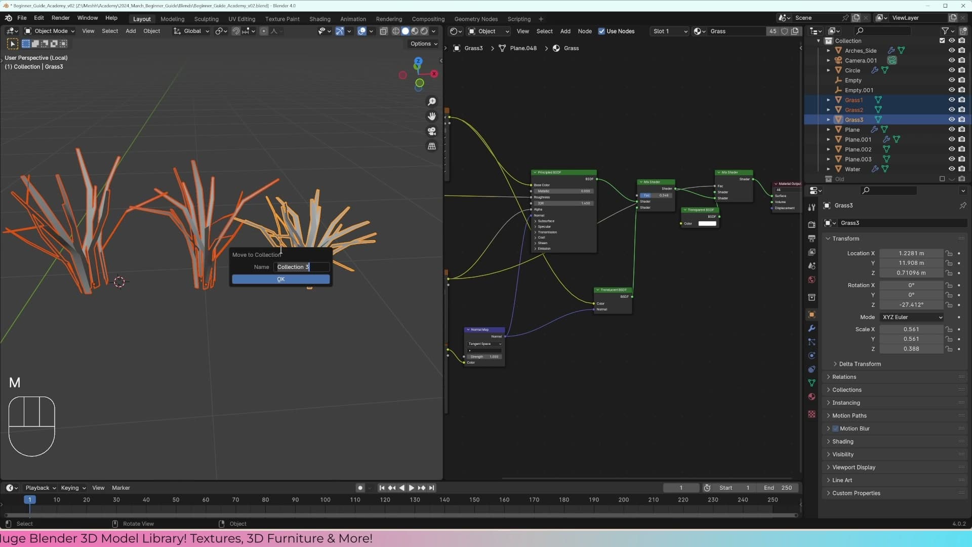
Back in object mode, select all three clumps, press M, choose New Collection and name it grass. The Geometry Nodes graph you build in the next module will point at this collection and pull instances from it at random. Anything inside the collection is fair game to scatter; anything outside it is ignored.
First Geometry Nodes setup: distribute and instance
The core pattern of every Blender scatter system: Distribute Points on Faces feeds a Join Geometry (so you keep the original surface), and Instance on Points replaces those points with your grass collection.
Understanding Group Input and Group Output
With the new plane still selected, switch the workspace to the Geometry Nodes editor and click New on the header to spin up a fresh node group. The default graph contains exactly two nodes: a Group Input on the left exposing a single Geometry socket, and a Group Output on the right with a matching socket. The wire between them is the entire setup. Whatever geometry comes in, the same geometry leaves untouched.
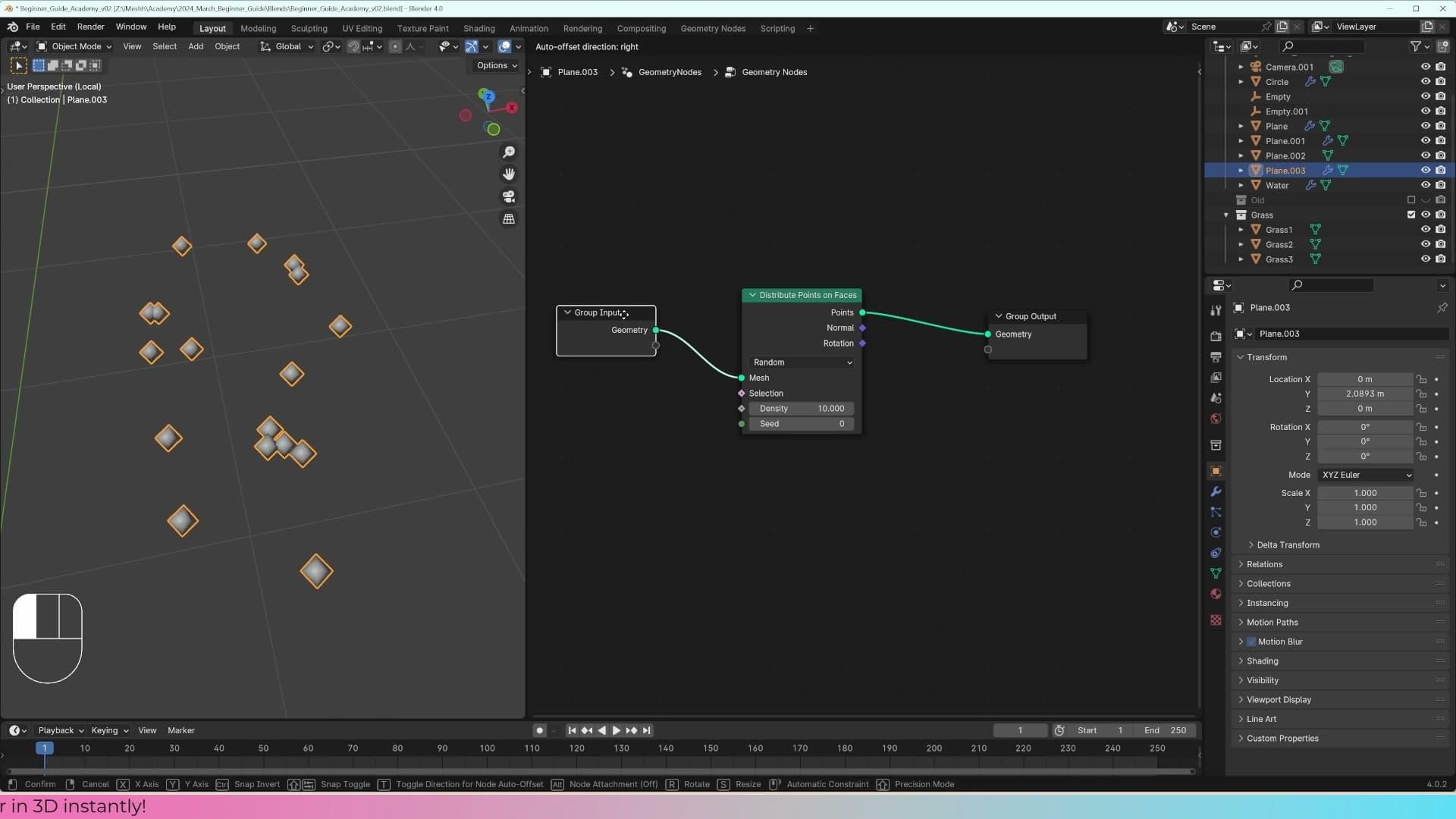
Unplug that wire and the output disappears from the viewport entirely. That is the mental model to hold on to: the Group Input is the mesh the modifier started with, the Group Output is what the modifier produces, and every node you add from now on sits between those two endpoints.
Distribute Points on Faces with Join Geometry
Press Shift+A and search for Distribute Points on Faces. Drop the node into the chain between Group Input and Group Output. The plane disappears from the viewport and is replaced by a sparse cloud of points scattered across its surface. Pull the Density slider up and the points multiply until the shape of the plane is implied by the cloud itself.
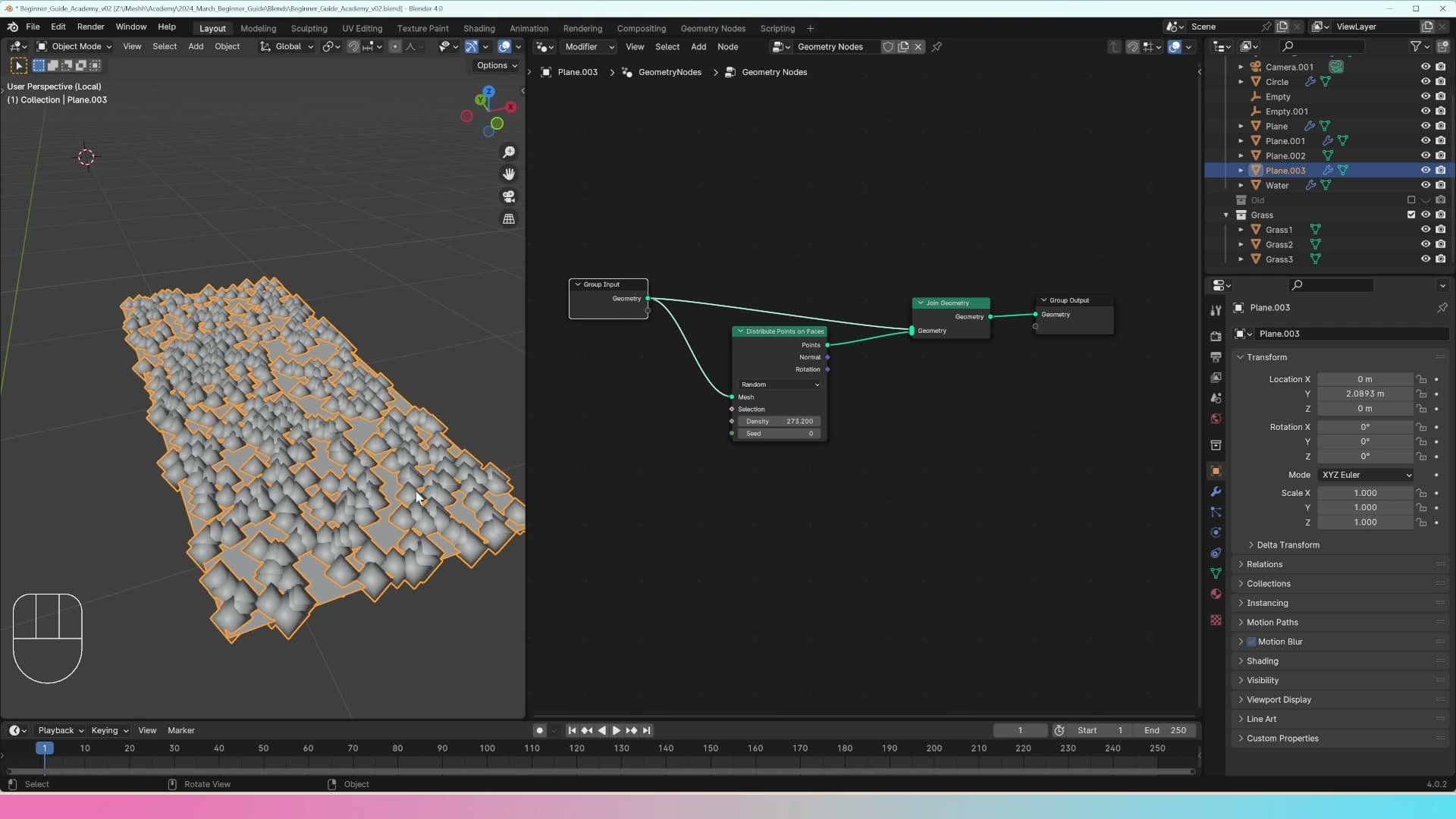
The plane is still driving the scatter. Switch into edit mode and move the geometry around and the points follow. But you have lost sight of the surface itself, and for a grass scene you generally want the ground mesh visible alongside the scattered blades.
To put the plane back, press Shift+A again and search for Join Geometry. Drop it just before the Group Output. Wire the original Group Input geometry into the first slot and the Distribute Points on Faces output into the second. Both now feed the Group Output: the plane is back in the viewport, and the scatter points sit on top of it.
Replacing points with Instance on Points
The scattered points are just a point cloud, useful as coordinates, but you do not actually want to render them. The next node replaces every point with a real mesh. Press Shift+A, search for Instance on Points, and slot it between Distribute Points on Faces and Join Geometry so the points pass through it on the way to the output.
Before bringing the grass in, prove the wiring works with a throwaway primitive. Press Shift+A → Mesh Primitives → Cube inside the node editor, scale the cube right down, and plug its geometry output into the Instance socket of Instance on Points. Every scatter point in the cloud is now replaced with a small cube, a clear visual confirmation that the pipeline is alive.
With the pipeline confirmed, swap the cube for the grass. Drag one of the grass blade objects from the outliner into the node editor and connect it into the Instance socket in place of the cube. The grass appears on the scatter, but it is offset, sitting some distance from the surface rather than on top of it.
That offset is an origin problem. The blade objects were modelled away from the world centre earlier, so each one's origin does not sit at the base of the blade. Instance on Points anchors instances by their origin, so anywhere there should be a blade you instead get an empty space with the blade flung off to one side. The next sub-lesson fixes that by snapping the 3D cursor to a known point and resetting each grass object's origin to match.
Randomising rotation, scale and picked instances
Plugging a collection straight into Instance on Points stacks the entire collection on every point. Pick Instance and Separate Children fix that, and Random Value nodes give each instance unique rotation and uniform scale so the scatter looks organic.
Pick Instance and Separate Children for collection scattering
Plugging the grass collection straight into Instance on Points has a problem that's hard to spot with grass blades, because every clump looks roughly similar. To see what's actually going wrong, disconnect the grass collection from the node for a moment and build a quick test scene that makes the bug obvious.
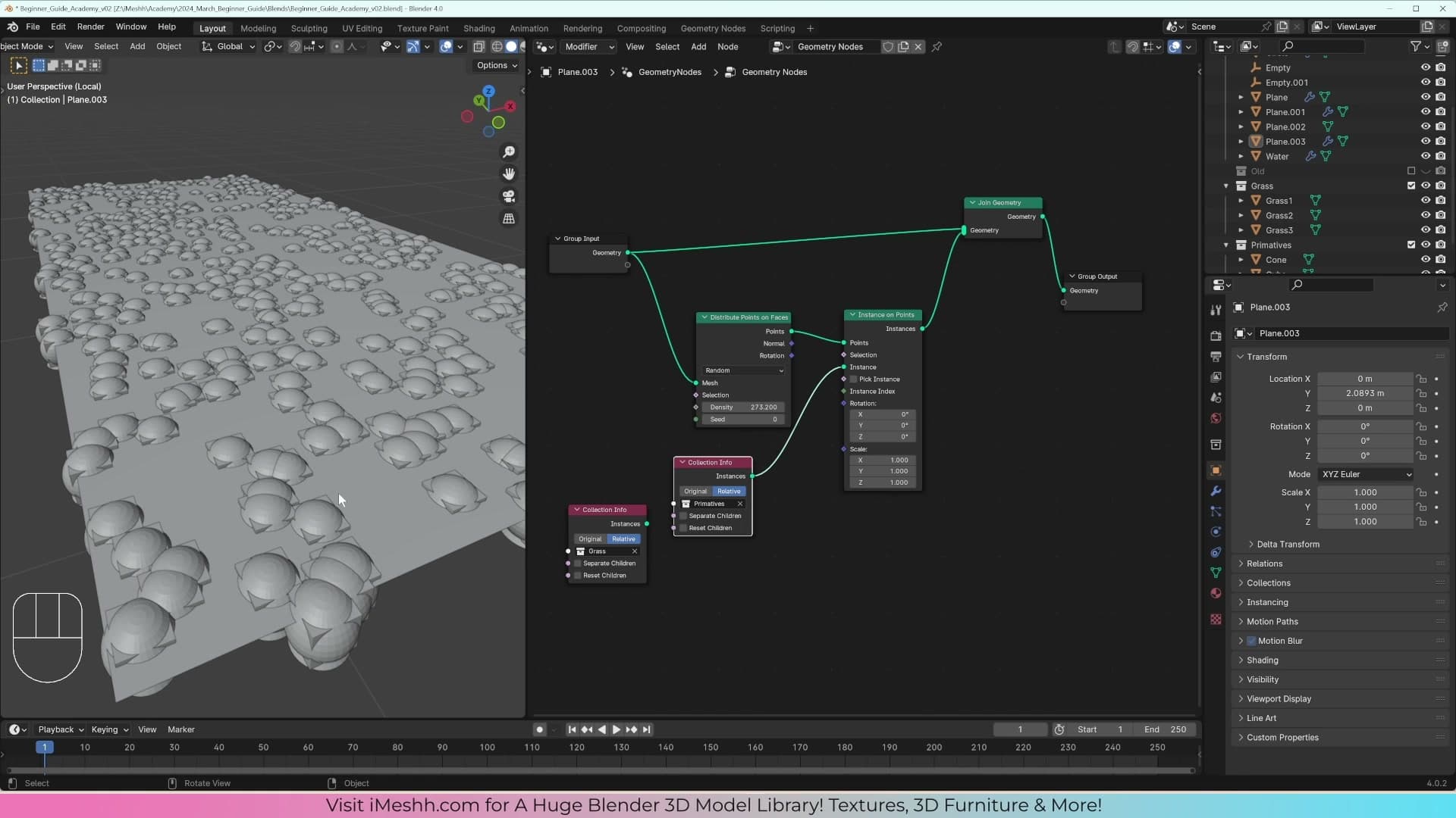
Press Shift+A and add a Cone, then a Cube, then a UV Sphere. Move all three into a new collection called Primitives. Drop that collection into the Collection Info node, switch it to Relative, and plug it into Instance on Points. Scale the result down so you can see individual instances clearly, and you'll spot that every point is spawning the entire collection on top of itself. All three primitives, stacked on every scatter point. The grass was doing exactly the same thing; the repetition was just camouflaged by the blades looking alike.
To force each point to pick a single object from the collection instead of all of them, find the Instance on Points node and tick Pick Instance. Then tick Separate Children directly above it. Now each point displays one object, but the distribution isn't truly random yet, so you'll see obvious repeating patterns rather than a clean scatter.
Press Shift+A and search for a Random Value node. Switch its type to Integer, then set the Max so the node outputs one of 0, 1 or 2 (three indices, one per object in the collection). Plug the output into the Instance Index socket on Instance on Points. The three primitives now appear across the surface in proper random distribution.
Swap the Primitives collection back out for your grass collection in the Collection Info node. With Pick Instance, Separate Children and the integer Random Value still wired up, each scatter point now picks a random clump from your grass. Scale the instances down to a believable size for the surface you're scattering on.
Randomising Z rotation with a Random Value node
Each clump is now picked at random, but they all face the same direction. The lawn reads as a copy-paste job rather than real grass. The fix is a second Random Value node feeding the rotation socket on Instance on Points.
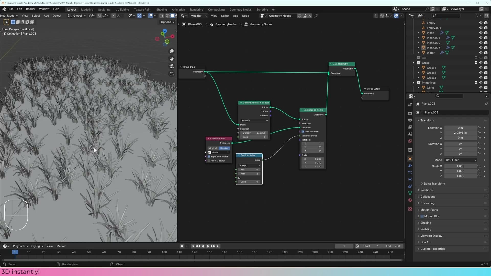
Grass grows straight up, so randomising X and Y rotation doesn't make physical sense. You'd end up with blades lying sideways. Only the Z axis needs to spin.
Press Shift+A, add another Random Value node and switch its type to Vector. Plug the output into the Rotation input on Instance on Points. By default the node randomises X, Y and Z together between 0 and 1, which isn't what you want.
Set the X and Y Min and Max all to 0 so those axes stay locked, then set the Z Max to 3.14. The rotation sockets work in radians, not degrees, so a value of 3.14 sweeps each clump across a full range of orientations. The scatter immediately looks more organic. No two adjacent clumps point the same way.
Randomising scale uniformly with a float
The clumps are picked at random and rotated at random, but they're still all exactly the same size. One more Random Value node handles scale, with one important catch.

The obvious approach is to duplicate the Vector random value already driving rotation and plug it into the Scale socket instead. Try that and the result looks wrong. Some blades come out visibly squashed, stretched or sheared. The reason is that a Vector random value generates three independent random numbers, one each for X, Y and Z, so every clump ends up with mismatched dimensions.
Delete the vector node. Duplicate the rotation Random Value, but this time switch its type to Float. A float outputs a single number, which Instance on Points applies uniformly to X, Y and Z, so each clump scales as a whole and keeps its proportions.
Set the Float Min to 0.2 and the Max to 0.5 so the scatter contains a mix of smaller and larger clumps without anything looking out of scale with the rest of the lawn.
Poisson Disk distribution and an exposed density slider
Random scatter overlaps itself. Poisson Disk enforces a minimum distance between points so clumps don't pile up. Then promote the density socket to the Group Input so you can tune scatter count straight from the modifier panel.
Switching to Poisson Disk to prevent overlap
Random distribution scatters points with no regard for what's already there, so once the density climbs you get clumps piling on top of each other. Switch the Distribute Points on Faces node from Random to Poisson Disk and you get two extra controls: a Density Max you can crank as high as you like, and a Distance Min that enforces a minimum gap between every scattered point.
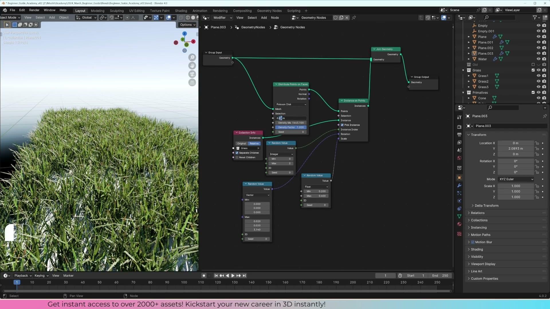
Push the density right up, then dial the minimum distance down a touch at a time until the bases of the grass clumps stop sitting on top of one another. The blade tips will still cross above the surface, but that's what real grass does. Poisson Disk is only spacing the spawn points, not the geometry that grows out of them.
Drop the viewer node and flip to render preview so you can see the result properly. With the bases spaced cleanly you can layer in a bit more rotation variety. Set the X and Y components of the random rotation to roughly 0.02 radians so the blades tilt slightly instead of all standing bolt upright.
From here it's a sweep to find a count that reads as full without grinding the viewport. Try 10,000; usually too many. 5,000 is closer, 2,500 often looks denser than the number suggests once the blades fan out. A minimum distance around 0.005 keeps the bases clean while the density climbs. Nudge the rotation randomness up to about 0.1 for a bit more break-up and the patch starts to feel natural.
Exposing density to the modifier panel
Before tweaking density, it's worth knowing the system follows the object. Tab into edit mode with the scatter plane selected, press Shift+D to duplicate, and the Geometry Nodes modifier rides along onto the new plane. Grass appears on the copy immediately with no extra setup.
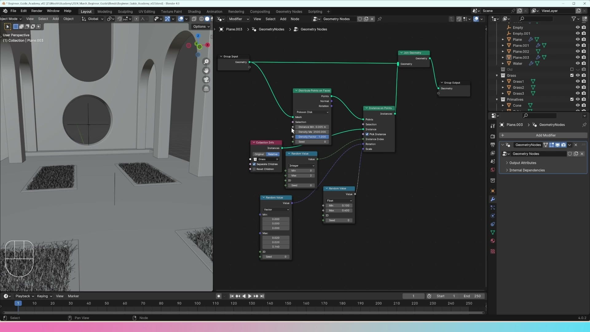
Once you start scattering tens of thousands of clumps the viewport begins to slow down, and you'll be dipping into the node graph constantly to nudge the density. There's a faster way: expose the density value to the modifier panel so you can tune it without opening the node editor at all.
In the node graph, drag a link from the Density Max input on Distribute Points on Faces back to the Group Input node. A matching slider appears on the Geometry Nodes modifier on the object. Drop it to a low value to lighten the load, push it up when you're ready to see the final density.
You can do this with any value you find yourself adjusting often, and you can edit the slider's maximum range on the Group Input too. Build up a handful of exposed sockets and you've effectively turned the Geometry Nodes modifier into your own custom tool panel for the grass system.
Finishing: dirt material, a second plane and final polish
The scatter is working. Now tidy it up. Swap the white base plane for a PBR dirt material so soil shows between blades, duplicate the plane for the back box, and tune density so the viewport stays responsive.
Replacing the white plane with a PBR dirt material
With the scatter running, drop into render preview and look at the grass under your scene lighting. If it feels too dense, dial the density socket down on the modifier panel. I try 2000 and even 1000 here to push more variety through the gaps. iMeshh subscribers also have access to a much larger grass library with more blade shapes baked in if you want a richer result, but the scatter you have built so far is already a solid foundation.
Before you can change the plane's material, fix two small staging issues that become obvious in preview. First, the grass tends to poke out through the side of the planter. Jump into edit mode on the planter, select all the inset faces with A, set the transform pivot to Individual Origins, and scale on X and then Y. Because each face now scales around its own median, you tuck the grass in from the walls instead of shrinking everything towards the planter's centre.
Second, some blades are clipping down through the plane. Select the affected grass clumps and lift them so they sit on the plane surface, then drop the plane back down to hide the gap. A couple of millimetres of overlap is all you need.
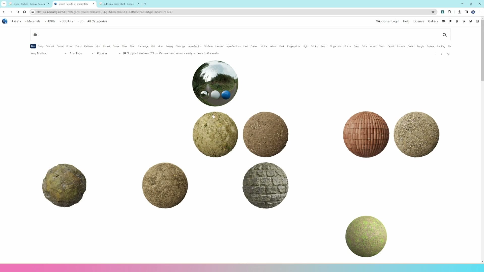
Now the material. Select the scatter plane, open the material slot and replace the existing plaster material with a fresh one by clicking New. Switch to the shader editor and bring in a PBR dirt set: base colour, roughness and normal map. Plug the colour into Base Color, roughness into Roughness, and route the normal texture through a Normal Map node into the Principled BSDF's Normal input. Set the colour and normal textures to Non-Color where appropriate. The soil tones now read through every gap in the scatter, which is what sells the planter as real.
There is no shame in using ready-made PBR sets for this. Every 3D studio works this way. Texture maps are the fastest and most accurate route to a believable surface, and freeing up time on materials means more time on composition and lighting.
Duplicating the scatter plane for the back box
Once the front planter is reading well, push the density up a touch and scale the inset faces out a little closer to the planter walls so the grass fills the box from edge to edge. Small tweaks here (a few hundred extra points, a slightly wider footprint) make the planter feel planted rather than sparsely seeded.
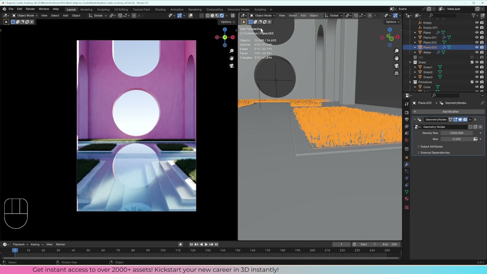
Now duplicate the whole setup for the back box. Select the scatter plane, press Shift+D to duplicate, then R to rotate 90 degrees so the plane sits the right way across the back planter, and scale on the X axis to stretch it to fit. Because the Geometry Nodes modifier travels with the duplicated object, the back planter is immediately full of grass with no nodes to rewire and no second collection to build.
This is the payoff of the procedural workflow you have just built. Any plane you drop into the scene with this modifier becomes a grass surface, and you can shape its footprint freely with normal mesh editing without touching the node graph.
Tuning density and hiding the scatter while editing
The blades may still feel slightly too big once you can see both planters together. Drop into the Geometry Nodes modifier and tighten the uniform scale range on your Random Value node. I land on a minimum of 0.05 and a maximum of 0.2. Smaller blades read as a denser carpet, so to compensate push the exposed density slider up to around 6000.
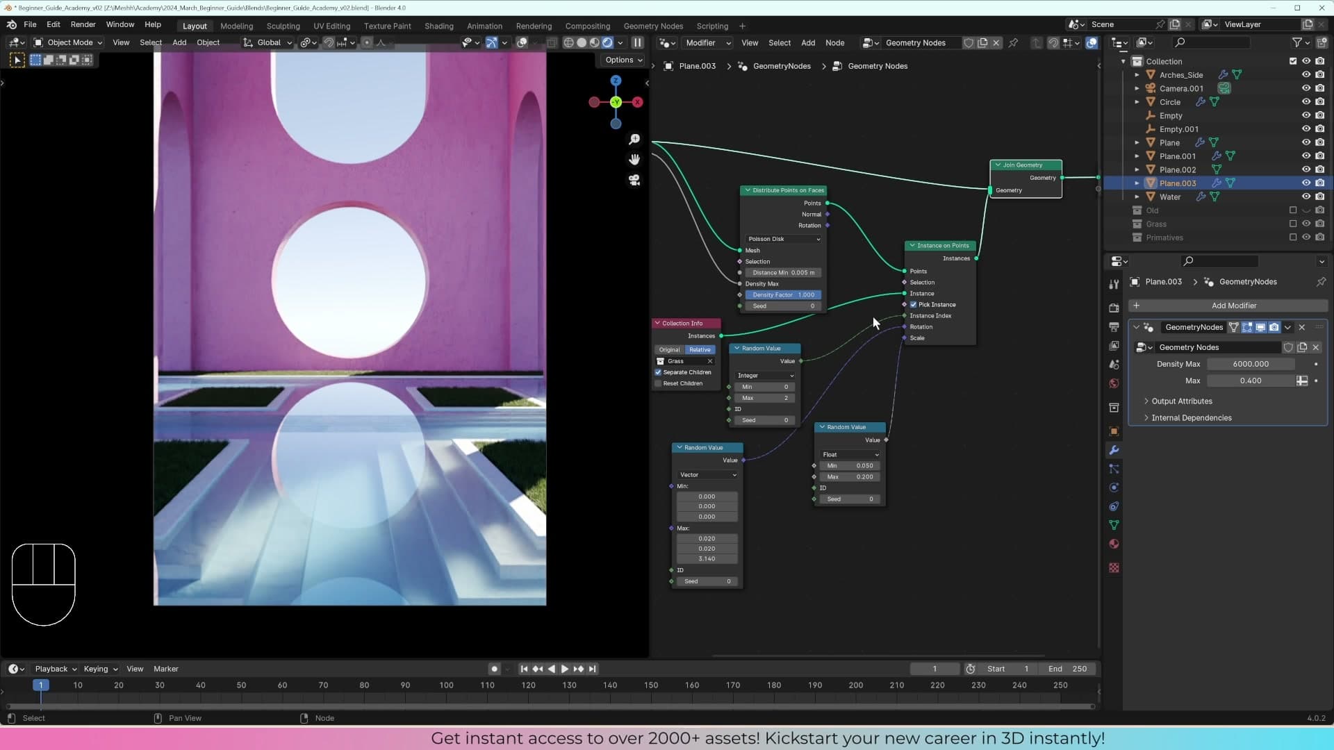
Keep an eye on viewport performance as you scale density. Each instance is a clump of several blades, so a 6000-point scatter is effectively millions of polygons in the viewport. If the scene starts dragging while you work on other props, you do not need to lower the density. Just toggle the modifier's viewport visibility off in the modifier header. The grass disappears from the editor but still renders, so you keep your final result without slowing down the rest of your work.
With both planters scattered, the scene is in a really good state for a first geometry nodes build. There is still room to push it further (more blade variants, a few flatter blades, some bigger clumps for variety), but if you have made it this far, you have the core scatter pattern that drives every procedural system in Blender. Next up is the hill in the background and the props that turn this from a grass test into a finished scene.
Tools and credits
Everything mentioned in this tutorial, with links.
- Blender (the renderer this entire build runs in).
- iMeshh (studio platform: project management, client review, asset library, invoicing). The asset library used in this tutorial is included with every iMeshh Pro plan.
- Poly Haven (free CC0 textures and HDRIs).
Pillar guide: Beginner Course hub