Project setup and reference image
Quick intro to the iMeshh marketplace, then loading the chair reference image as a 3D plane, rotating it upright and dropping into front view so we have plans to model against.
Tutorial intro and what we're building
Welcome to this iMeshh tutorial. Today you're modelling a chair in Blender, working from a single reference photo. Before opening Blender, a quick word on where the tutorials and assets live.

iMeshh runs as a 0% commission marketplace: sellers keep their full asking price rather than handing over fees of up to 60% that some other platforms take. A small subscription (roughly $1 a month at the time of recording) kicks in if you want to list more than 10 products or use over 2GB of storage, but the marketplace itself stays free to browse and free to sell on.
Load the chair reference as an image plane
Most chair builds start with a set of orthographic plans (front, side, top and back) that you model directly against. For this build a single perspective photo of the finished chair is enough; the silhouette and proportions give you everything you need to block out the seat shell and the leg positions.
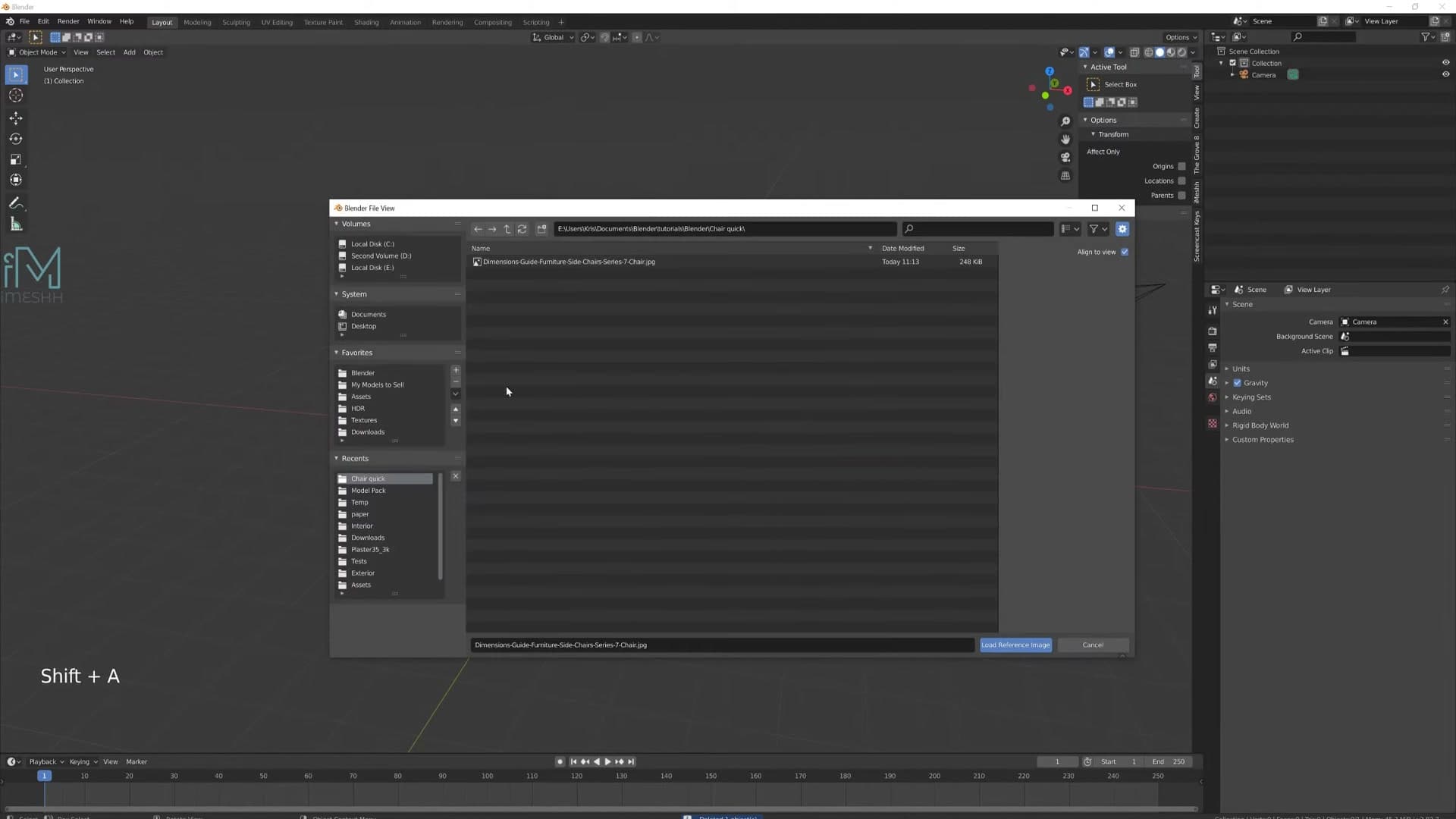
In a fresh Blender file, delete the default cube. Press Shift+A, open the Image submenu and click Reference. Before you pick the file, untick Align to View in the operator panel that drops down at the bottom-left. Leave that ticked and the plane spawns angled toward the viewport, which makes the next step fiddly. Then click Load Reference Image and choose your photo.
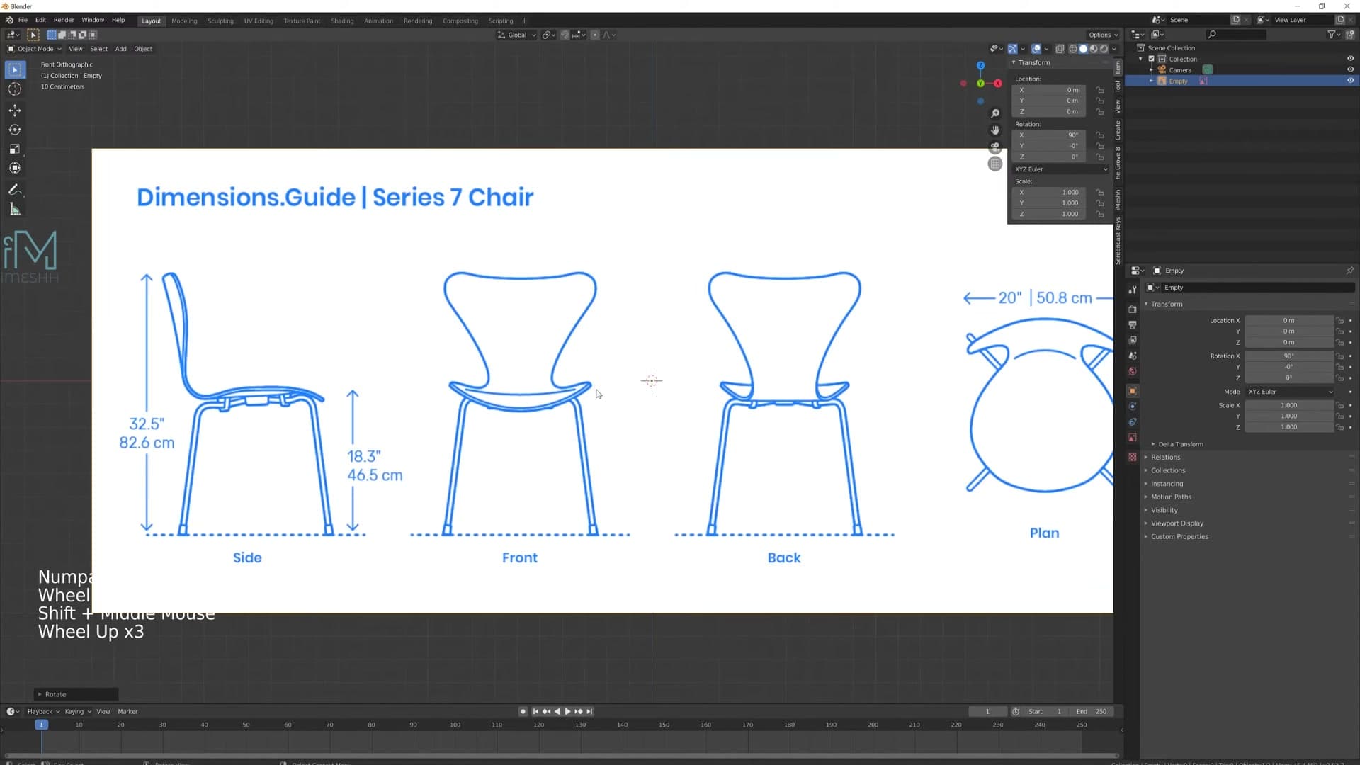
The image plane comes in lying flat on the ground, so stand it up: press R, then X, type 90 and confirm. Switch to front view with Numpad 1 and the reference is sitting square in front of the camera, ready to model against.
Block out the seat shell with a mirrored plane
Half a plane, a Mirror modifier and a handful of extrudes are enough to capture the entire seat profile. Proportional editing and clipping pull the shape into something organic.
Cut the plane in half and add the Mirror modifier
With the reference image in place, move to the front view and Shift + right-click to drop the 3D cursor where you want the seat to start. Press Shift+A and add a plane, then scale it down so it sits roughly the width of the chair seat in the reference. Hit Tab to drop into Edit Mode.
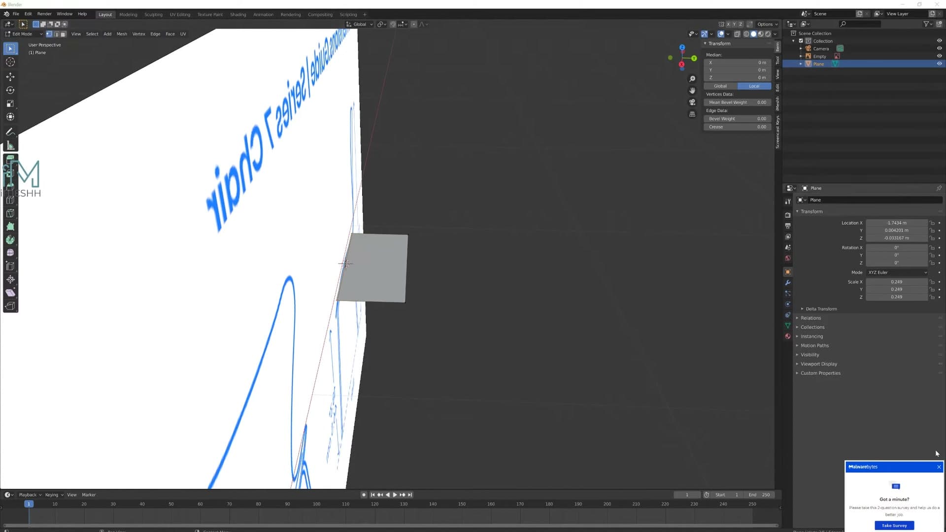
Press Ctrl+R to add a loop cut straight down the middle, splitting the plane in half. To isolate what you're working on, jump into Local View so only the plane is visible. Select the two vertices on one side of the loop cut and delete them. You should be left with a half-plane sitting flush against the centre line.
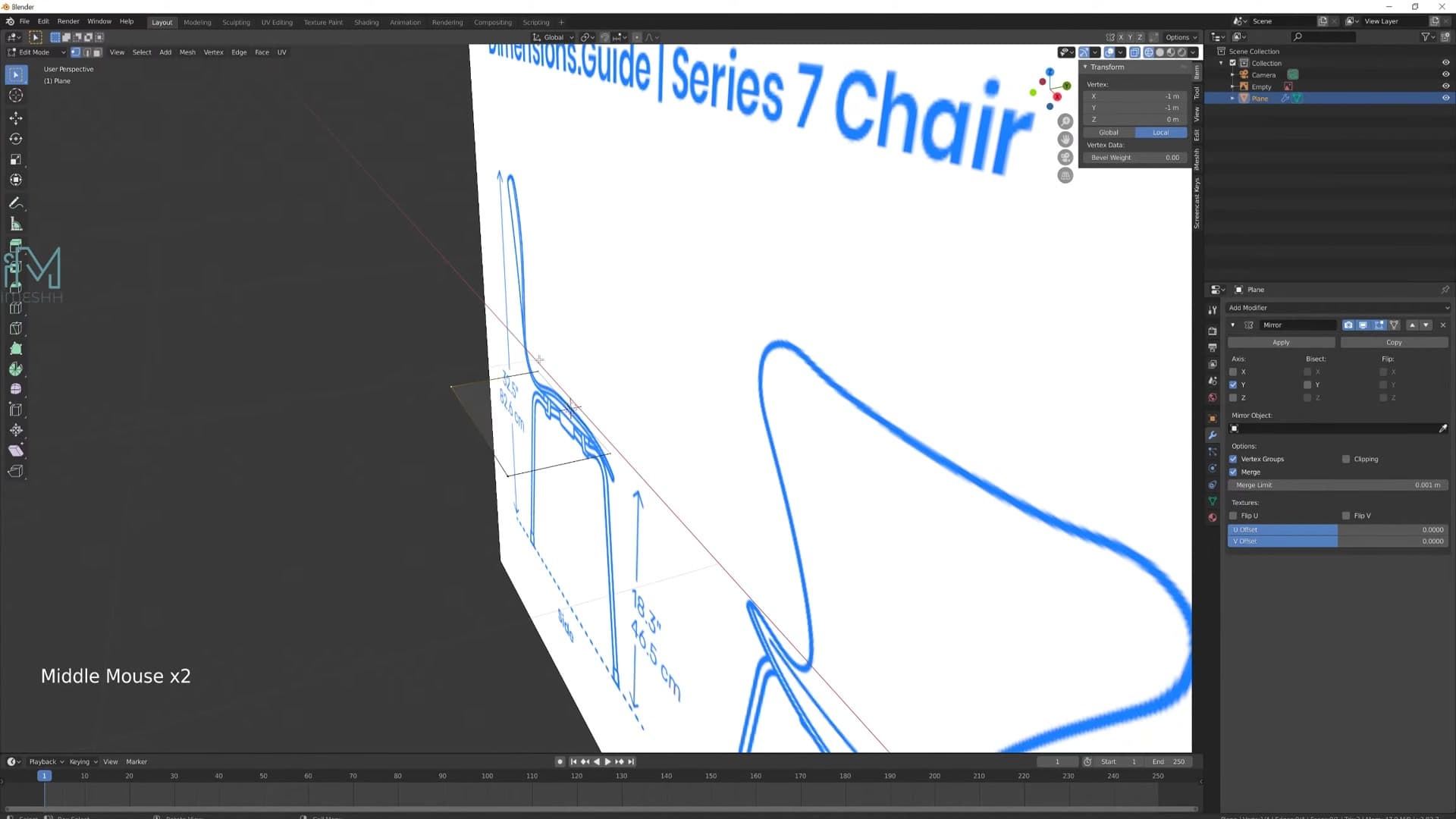
Open the Modifier Properties panel and add a Mirror modifier. Check the viewport: if the mirrored half pops out on the wrong side, tick the opposite axis (and untick the original) until the reflection sits where the other half of the chair belongs. From here on, every vertex you push on the working half mirrors instantly across the centre. That's what you want for a symmetrical chair.
Extrude the seat profile from the front view
Hop back to the front view with Numpad 1 so the reference photo is staring you in the face. Select the top edge of your half-plane and press E to extrude, then trace the silhouette of the seat upward, one extrude at a time, following the curve of the chair as it climbs out of the base. Where the centre of the seat sits, push the extrude straight up rather than chasing the photo exactly; you'll pull the edge back out into its true shape once the top profile is in place.
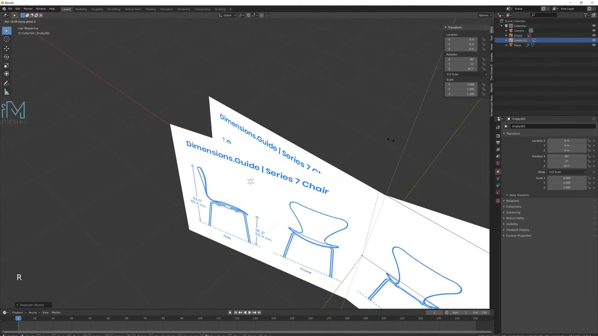
Once the front profile is roughed in, you'll want a second guide loop running the other way. Select the working geometry, press Shift+D to duplicate, then type R Z 90 to spin the copy ninety degrees around the vertical axis. Press Numpad 3 to view it from the side and slide the duplicate into position so it overlaps the seat where the cross-section should be.
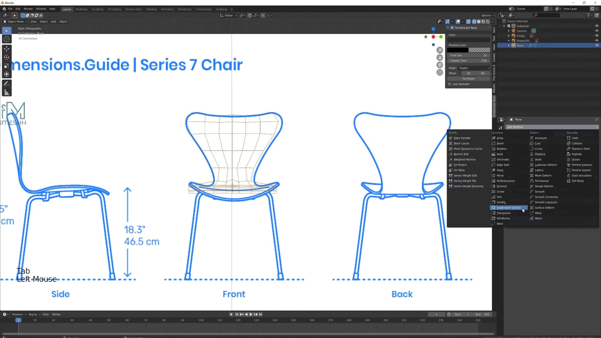
Now grab individual vertices and nudge them into shape, trying to keep them evenly spaced rather than clustering at the corners. To temporarily preview how the surface will read once it's smoothed, add a Subdivision Surface modifier. The lumpy polygon shell suddenly looks like a soft seat cushion, which makes it much easier to judge whether the silhouette is correct.
Add the top profile and refine with proportional editing
The seat reads well from the front, but there's nothing yet defining the back rail across the top of the chair. Select the edge you want to clone, press Shift+D to duplicate it, then rotate it ninety degrees on Z and another minus ninety degrees on Y so it sits flat across the top of the seat. Slide it down into position and you've got a second profile loop to push and pull against.
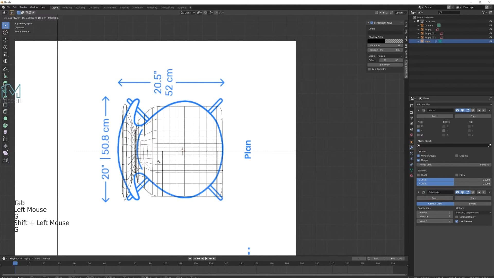
To shape the seat without manually adjusting every vertex, you'll lean on proportional editing, but first you need to exclude the bits you don't want dragged along. Select the vertices that should stay put (the rim of the seat, for example), press H to hide them, and now proportional editing can't touch them. Press O to turn proportional editing on; from here, moving one vertex will smoothly pull its neighbours along with it.
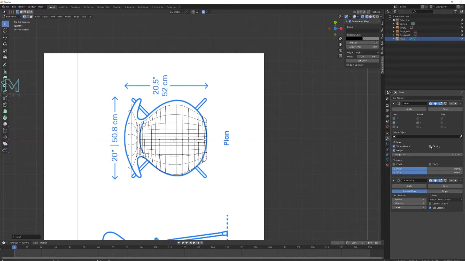
Switch on Clipping in the Mirror modifier options too. Clipping locks any vertex that touches the mirror plane so it can't be dragged across, which keeps the centre seam welded shut while you're shoving geometry around with proportional editing.
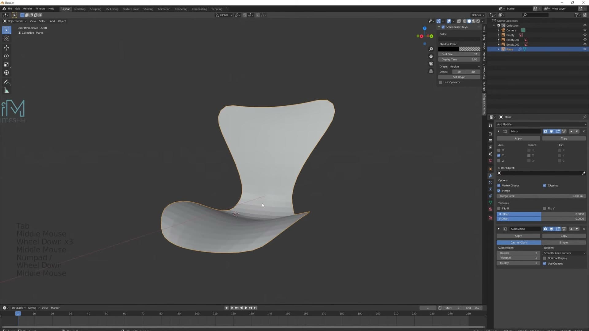
Push the back of the seat up to form the rest, drop the front edge slightly so the seat dips where someone would actually sit, and lift the side rims into a gentle lip. Right-click on the object and choose Shade Smooth. The faceted polygons resolve into a soft, continuous surface, and what was a flat plane two minutes ago is now recognisably a chair shell.
Thicken with Solidify, Bevel and Subdivision
The modifier stack does the heavy lifting: Solidify gives thickness, Bevel-by-angle rounds only the real corners, Subdivision smooths everything. Order matters.
Stack Solidify, Bevel and Subdivision in the right order
Before adding any thickness, turn off the Subdivision Surface so you can see the raw geometry you're actually working with. Then add a Solidify modifier. That's what gives the single-sided shell real depth.
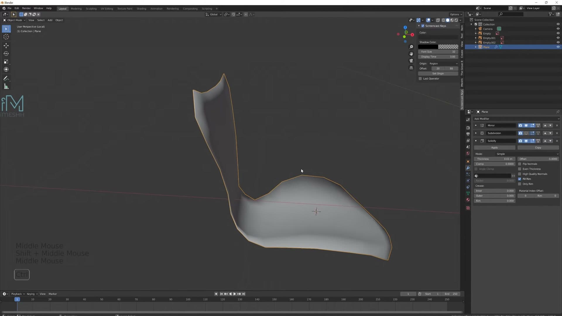
Apply scale on the seat so the Solidify thickness reads in real-world units rather than scaled ones, then drag the Subdivision Surface modifier down below the Solidify in the stack. Turning Subsurf back on now shows the shell with thickness and smoothing, but the edges look too sharp at the corners.
To round those edges off, add a Bevel modifier and move it above the Subdivision Surface so the order reads Solidify → Bevel → Subdivision. Bump up the segments a touch for a smoother round, then switch the limit method to Angle and set the angle threshold to 80°. The point of the angle limit is that you only want the bevel to fire where edges meet at close to 90°, which on this chair is just the genuine corners. The smooth curves you've already built stay untouched.
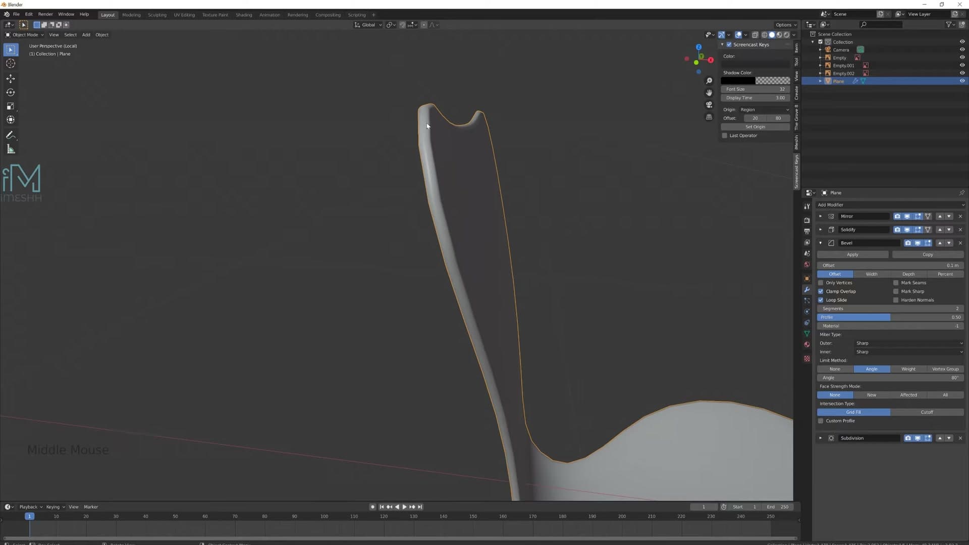
Now lower the bevel width right down. Something around 0.002 is enough to read as a soft chamfer without losing the silhouette. If the second subdivision starts dragging the viewport, drop its Quality value down; the default is heavier than the shape needs.
Fix bad shading on the seat edge
Once the stack is on, you'll probably spot some odd shading running along one edge of the shell, where the surface looks like it's pinching or doubling back on itself. The first thing to try is enabling Even Thickness on the Solidify modifier, which forces the offset to push uniformly even where the underlying mesh angles change.
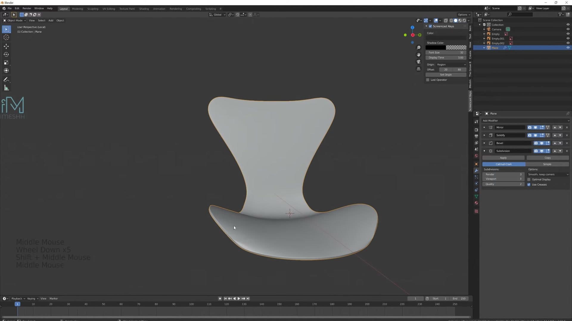
If Even Thickness alone doesn't clear it (and on a curved seat like this it often won't), drop into Edit Mode and nudge the offending vertex by hand. A single vert sitting slightly too sharp is usually enough to throw the whole edge out. Pull it back into line and the edge pops into place.
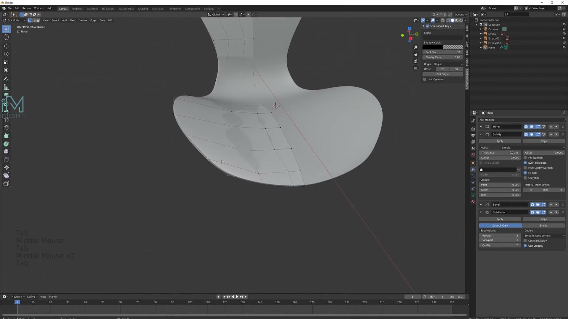
Finish by walking around the seat and easing any verts that break the silhouette. You want the form to follow as a continuous curve with no bits poking out. Small tweaks at the base mesh pay off later, because the modifier stack amplifies every kink underneath it.
Model the legs with Bezier curves
Bezier curves with Geometry → Bevel give you editable pipe legs you can keep refining. Mirror across Y so both legs update together, and add a curve-level Subdivision to kill the jaggies.
Add a Bezier curve at the chair centre with Mirror
With the seat shell looking right, it's time to move on to the legs. Slide the shell up out of the way so you can see the base of the chair in the reference. Each leg runs in toward the centre of the chair and meets a small connector box, so the same mirror-and-edit trick that worked for the seat will work for the legs too.
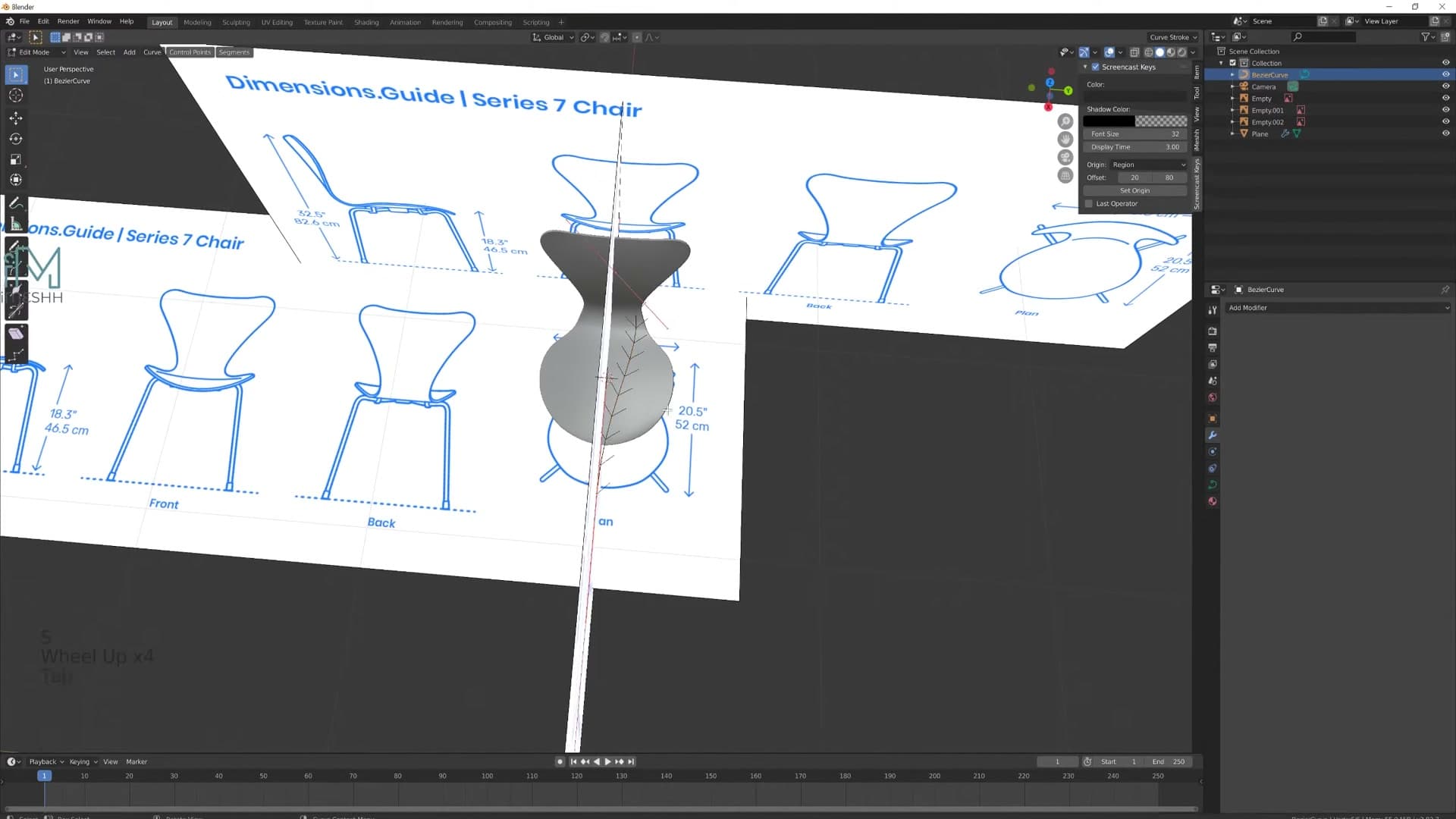
Snap the 3D cursor back to the chair centre with Shift+S → Cursor to Selected, then add a curve with Shift+A → Curve → Bezier. Adding it at the world origin is deliberate: in Edit Mode you can drag the control points wherever you like and the object origin stays put at the chair centre, which is exactly what a Y-axis Mirror needs in order to reflect cleanly across the chair.
Add a Mirror modifier and switch the axis from X to Y. Now any edit you make to one leg curve is reflected on the opposite side automatically. You only ever shape one leg.
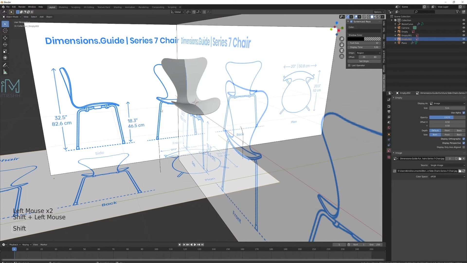
Rotate the whole curve 90° so it sits along the leg in the reference, jump to side view, and roughly position and scale the curve down to leg size. The bezier handles are hard to read against the busy reference, so drop the opacity on the reference image planes until the curve is clearly visible against the plans.
Shape the leg profile in side view
Grab the end control point of the curve (the tip of the leg) and scale it down so the tube tapers slightly. The bottom section of the leg is fairly straight, so position that part as a clean line first, then shape the upper part so the leg bows outwards a touch and then back in towards the seat. Match the silhouette in the reference rather than trying to be exact; the side-on plans are slightly inconsistent depending on which view you trust.
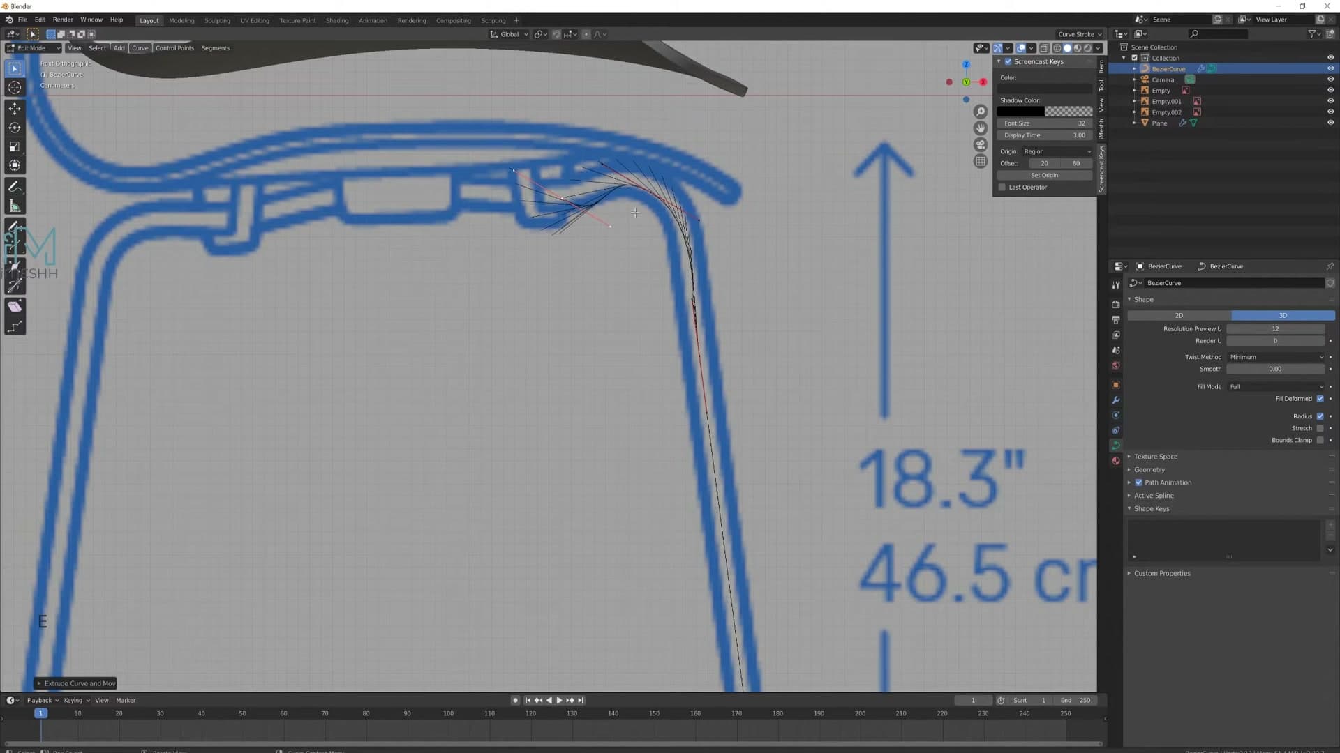
There are plenty of ways to model a pipe in Blender. A cylinder extruded along a path is one option. But a bezier curve gives you the most freedom to keep tweaking the shape after the fact, which matters when you're chasing a real reference photo.
The bezier tangent indicators get noisy fast and start to obscure the control points you actually need to grab. Turn them off via the Overlays dropdown in the viewport header: click the arrow next to the overlays icon, find Normals, and toggle them off. The handles stay visible without the extra clutter.
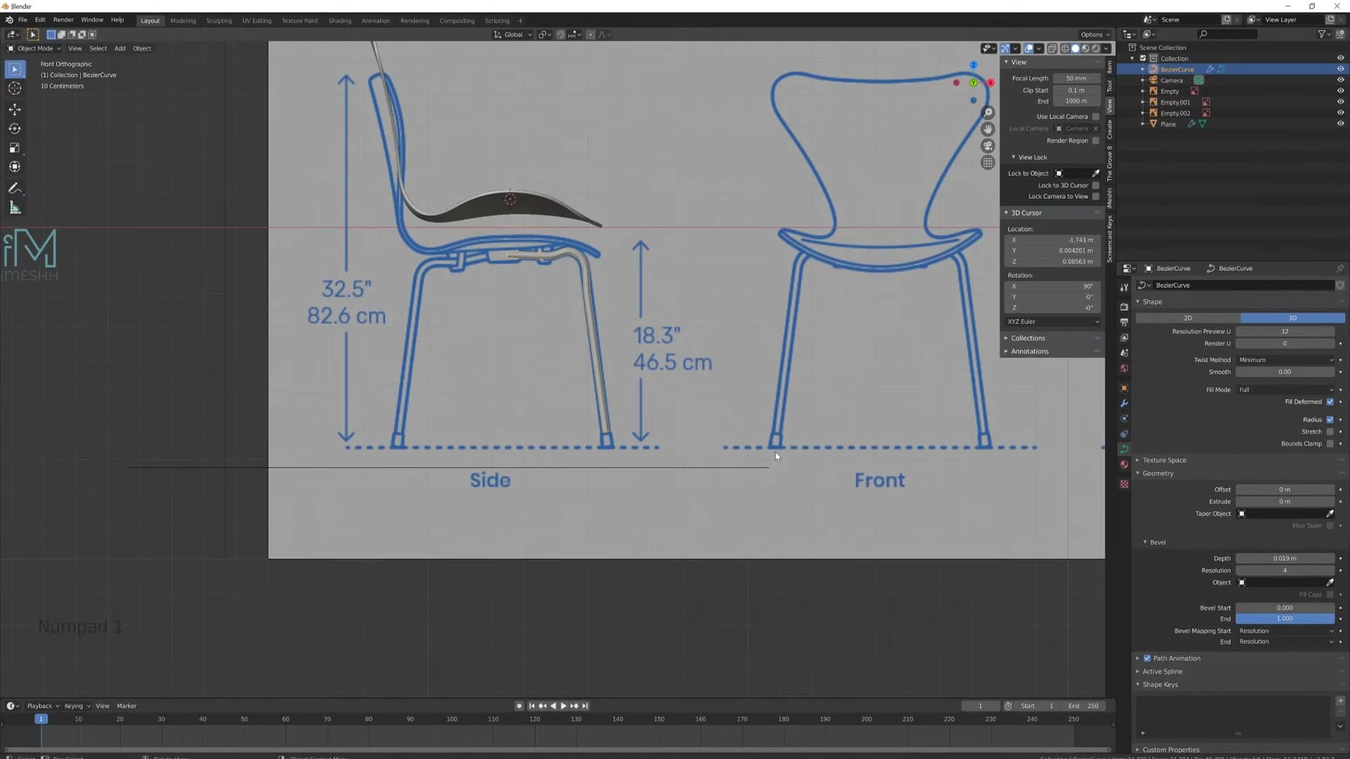
Tighten any corner that looks too soft by sliding control points closer together, and add a final control point near the seat connection so the curve ends exactly where the connector box will sit.
Give the curve thickness with Geometry → Bevel
So far the leg is a one-dimensional line, useful for shaping but invisible at render time. To give it tube geometry, head to the curve's Object Data Properties tab, expand the Geometry section, and find the Bevel sub-panel. Increase the bevel Depth until the curve takes on the right pipe diameter for the leg.
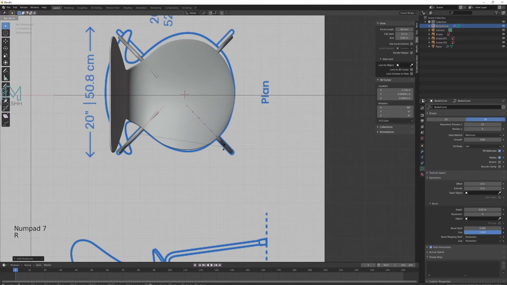
Hold Shift while dragging the slider to slow the value down. Much easier to dial in a small diameter without overshooting.
Hop back to front view with Numpad 1 to sanity-check the thickness against the reference. With the geometry switched on, the leg now reads as a solid tube rather than a hairline, and you can still go back into Edit Mode at any point to refine the underlying curve. The bevel updates live.
Duplicate the leg for the front pair
The back pair of legs is already covered by the Y mirror. The front pair needs a duplicate of the same curve, rotated 90° on Z. In Edit Mode, press Numpad 1 for front view, A to select everything, then Shift+D to duplicate and move the copy along the X axis away from the original. Switch to top view and press R Z 90 to rotate the duplicate so it now points forwards.
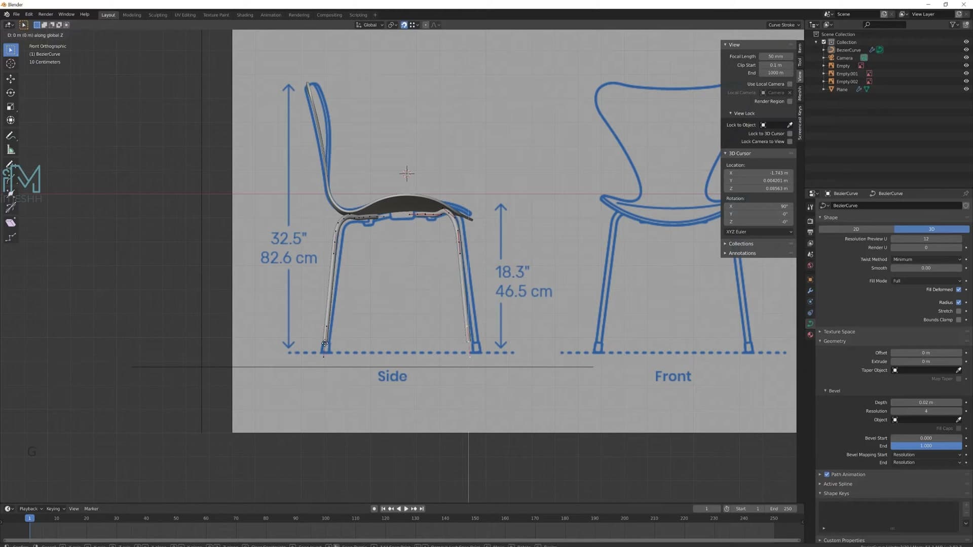
The front legs usually need a slightly different shape from the back pair. Press O to toggle proportional editing so you can nudge whole sections of the curve in one go without grabbing every point individually. Soften the curve wherever it looks too aggressive against the reference.
Both leg pairs need to sit at exactly the same height. Grab the bottom control point of one curve, toggle snapping on with Shift+Tab, and make sure the snap target is set to Vertex in the snap dropdown. Then press G Z and hover over the matching point on the other leg. The moved point will lock to that exact height. Select both points together and slide them down to your final ride height.
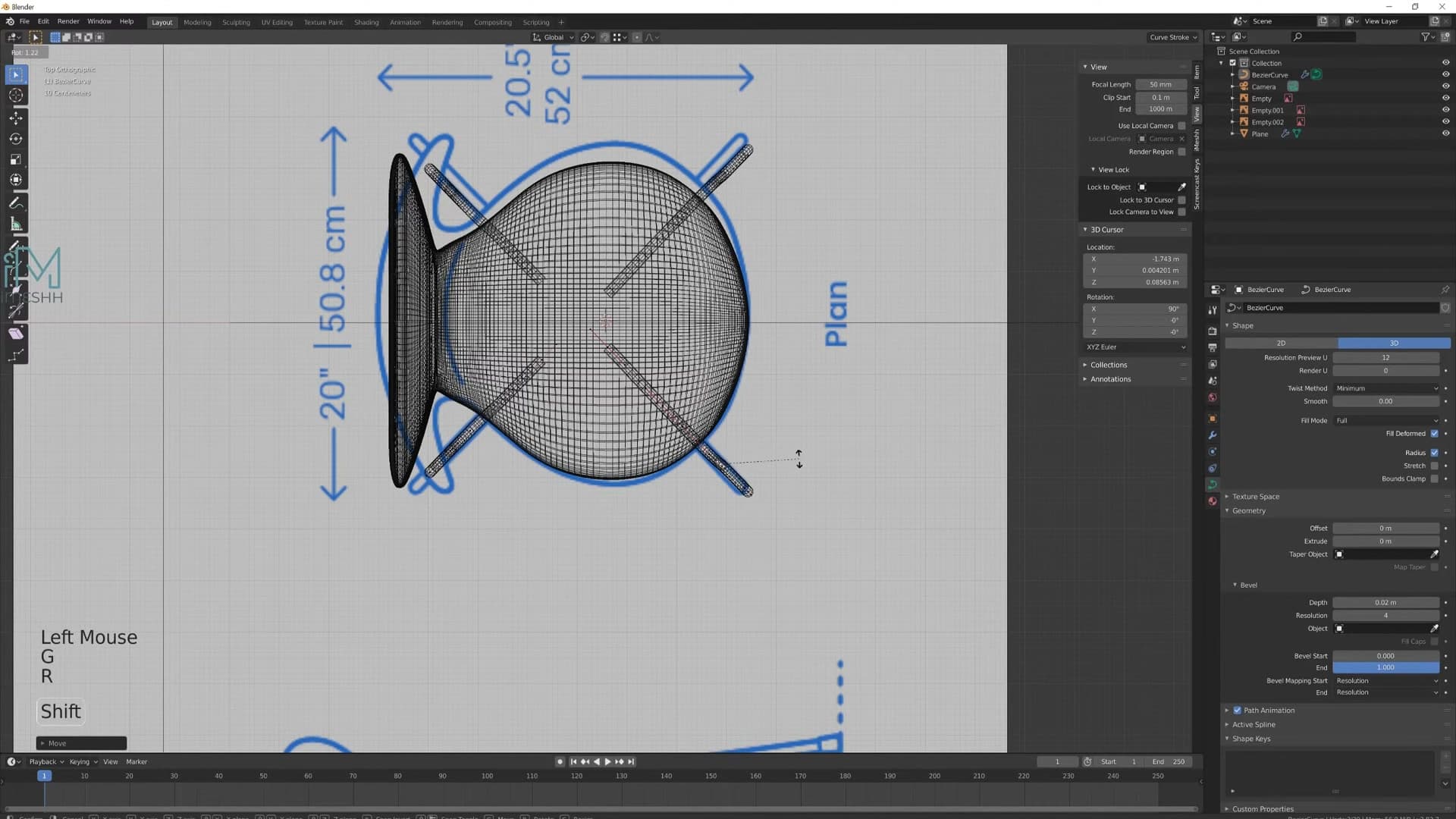
Toggle snapping back off with Shift+Tab when you're done, then nudge the central connection points closer to the chair centreline if the legs are kinking outwards more than the reference shows. Straighten any segment that's gone wonky during the snap and the leg base is finished.
Apply modifiers, mark seams and unwrap the seat
After the recording dropped out, the seat's Bevel and Solidify get applied so we can mark seams along the chair's edge loop and unwrap it cleanly for materials.
Apply modifiers and mark the seat seam
The recording dropped out during this section, so the next stretch is a quick recap of what happened off-camera. Both the Bevel and the Solidify modifiers were applied, baking the rounded edges and the shell thickness into the mesh. That's a necessary step before marking seams, since unwrapping a shell that still has live modifiers on top of it tends to give unpredictable results.
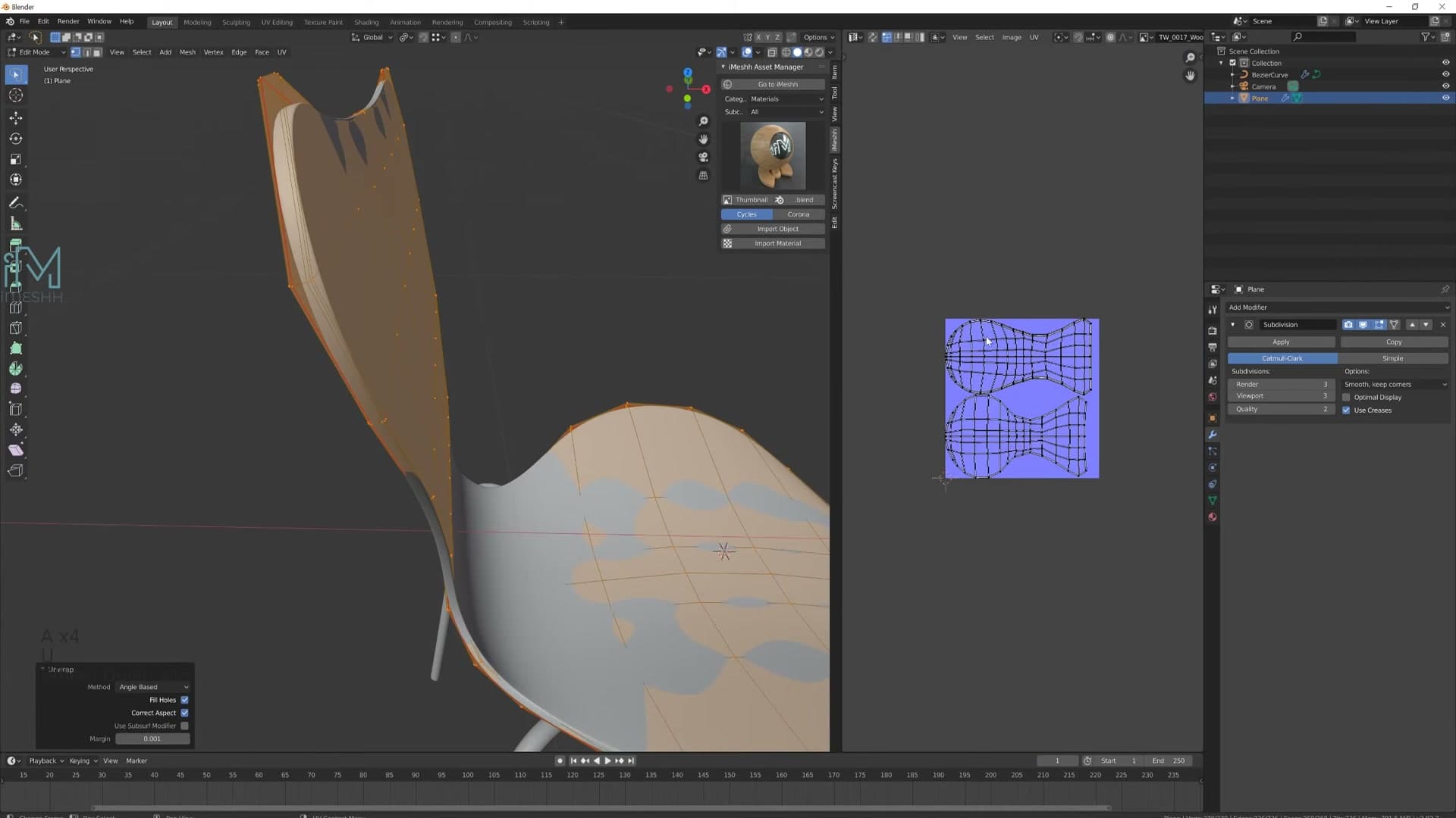
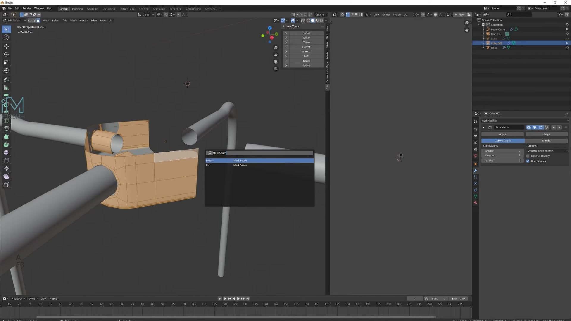
With the modifiers committed, set up a seam along the outer edge loop of the seat. Alt+click on an edge anywhere along that loop and Blender selects the full ring in one go. Press F3 to open the search menu, type Mark Seam and run it. The loop turns red, telling the unwrapper where to slice the UVs open.
Then select the whole mesh with A, press U and choose Unwrap. The seat shell flattens into a single clean UV island, ready for a material.
Curve the seat sides inward and apply material
Looking at the seat from the side, the long edges should curve gently inward, a detail that was missed the first time round. To fix it, grab the vertices along one side, press O to enable proportional editing, and translate them along the relevant axis. The proportional falloff softens the move into the surrounding geometry, and you can scroll the mouse wheel to dial the radius of influence up or down until the curve reads the way you want.
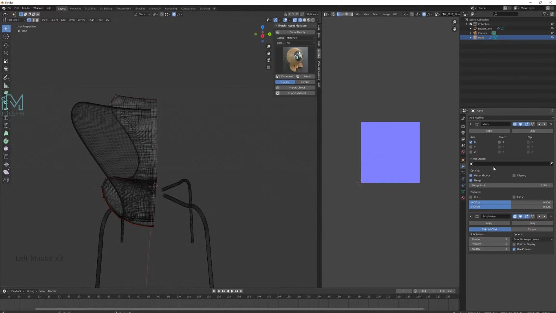
Spend a minute nudging the side vertices around until the silhouette flows cleanly from above. A few stray vertices may sit slightly off the line; pull them straight by hand so the sweep along each side is smooth and even.
Once you start shaping the outline in earnest, it pays to be working on a fresh mirror so every change reflects across both halves as you go. Delete the mirrored side, add a new Mirror modifier, drag it to the top of the stack and set the axis to Y. Now any tweaks to the working half propagate automatically.
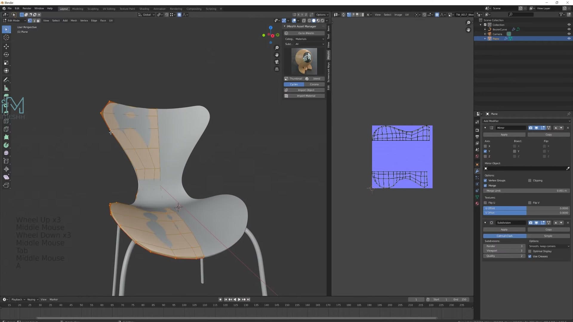
When the shape is locked in, apply the Mirror modifier so the mesh becomes a single object, then re-unwrap to refresh the UVs. Drop the navy fabric material onto the shell from the iMeshh Asset Manager. The seat is finished.
Build the leg connector box
A simple cube with edge loops becomes the under-seat block the four legs slot into. Inset the bottom face to start cutting the leg holes.
Add a cube and shape it with edge loops
With the seat shell finished, the next layer of detail is the small box that sits under the seat and houses the four legs. Before adding it, I apply a wood material to the seat using the iMeshh Asset Manager so the shell stops competing with the rest of the build visually.
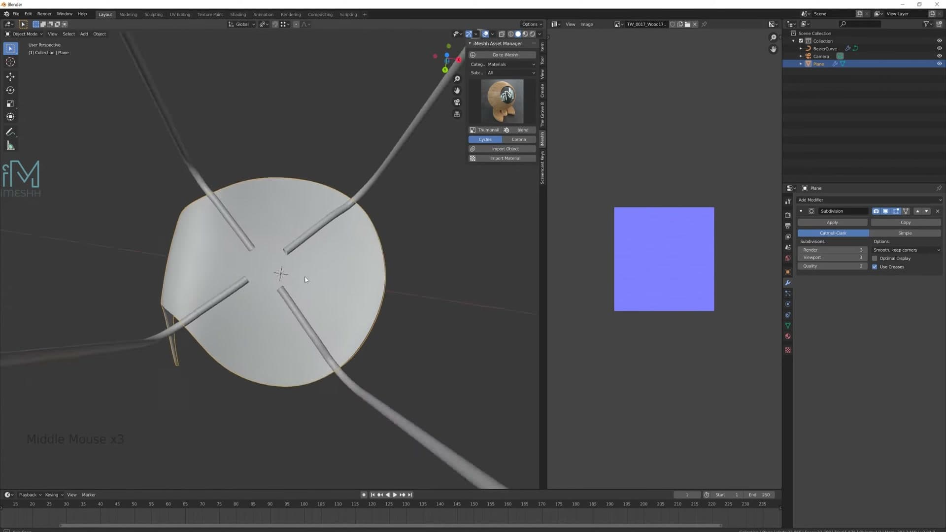
Snap the 3D cursor to the seat first so the new geometry spawns in the right place. With the seat selected, press Shift+S and choose Cursor to Selected, then Shift+A and add a cube. Scale it down with S, drop it underneath the seat with G, and squash it into a shallow block roughly the width of the under-seat area.
Turn off proportional editing if it's still on from earlier, then tweak the cube's side faces in edit mode until the proportions match the reference. The shape is rough on purpose; the modifiers and edge loops do the actual sculpting.
Now mirror it. In local view (so the seat doesn't get in the way), add a horizontal edge loop with Ctrl+R through the middle of the cube, delete one half, and add a Mirror modifier set to the Y axis. Finish by deleting the top face. The seat covers it and you don't want hidden geometry messing with subdivision later.
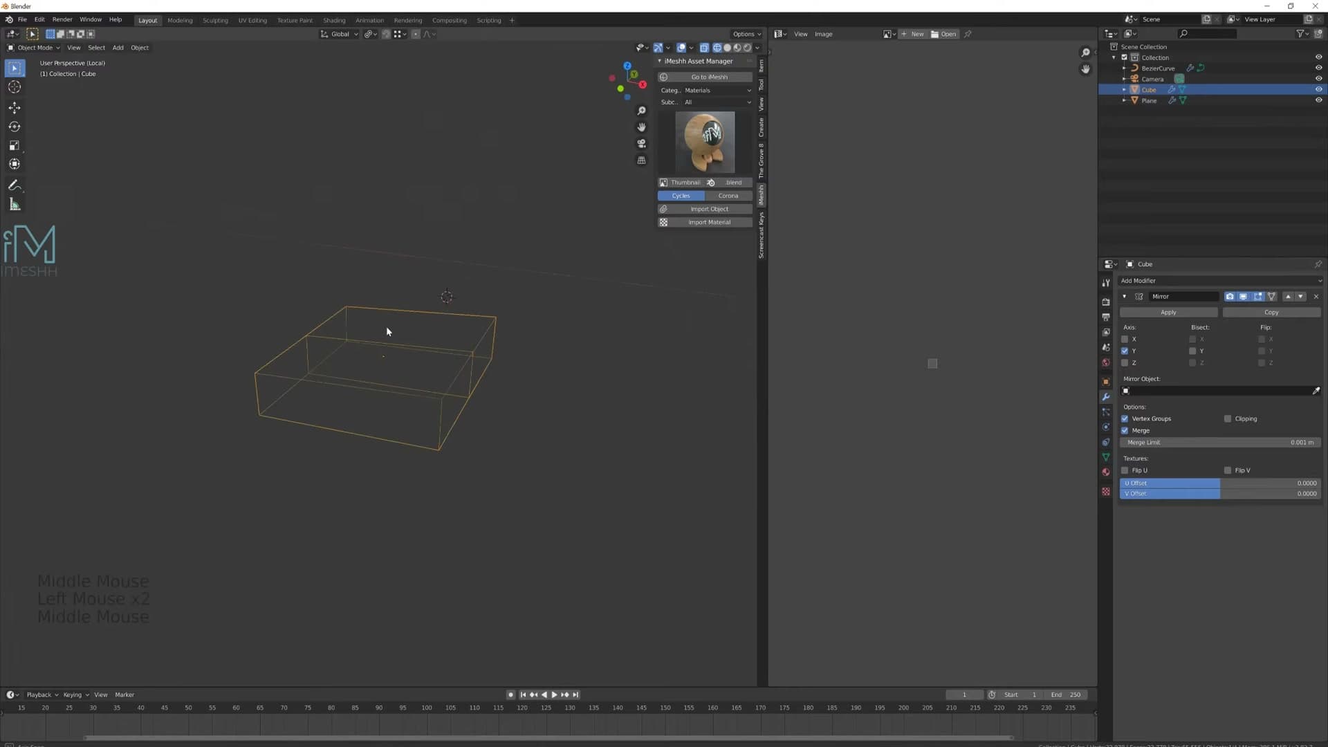
Inset the bottom face for the leg holes
The box needs softened corners and a recess on the underside for the legs to slot into. Start by smoothing the front edge: select the two vertical edges on the front of the block, press Ctrl+B and add a single bevel segment to round the corner.
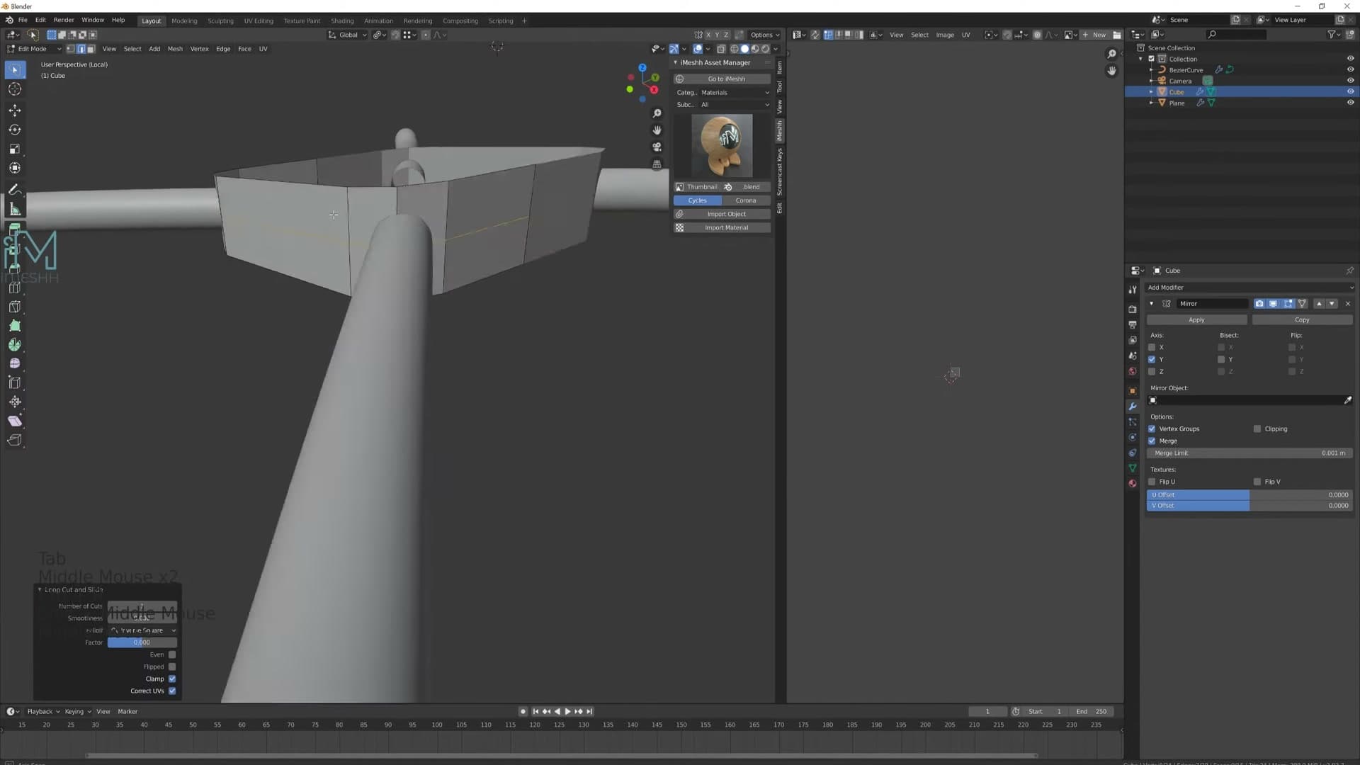
Flip to top view and check that the leg cylinder (still in place from earlier modules) is sitting directly in the middle of the connector box. Nudge the box if it's off-centre, and the mirror modifier will keep both sides aligned automatically. Add another edge loop around the front, bevel it with Ctrl+B, and confirm the cylinder is still centred.
Now cut the recess. Select the bottom face and press I for inset. Because the mirror modifier is active, you have to untick Individual Faces in the inset operator panel. Otherwise the inset breaks at the mirror seam and you get two disconnected loops where you want one continuous edge.
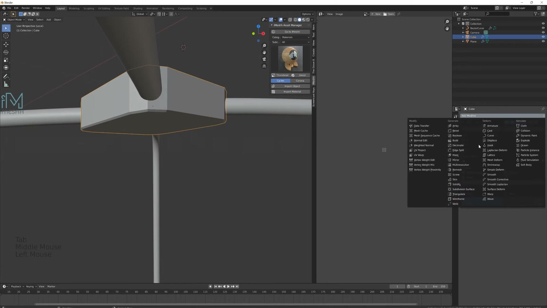
With the inset in place, grab the new inset edge and run Ctrl+B again to add a bevel around it. That gives you a tidy recessed pocket on the underside, ready to receive the legs.
Add supporting loops and shade smooth
Add a Subdivision Surface modifier to the box. The corners will instantly go too soft, so you need supporting edge loops to pull the geometry back into shape.
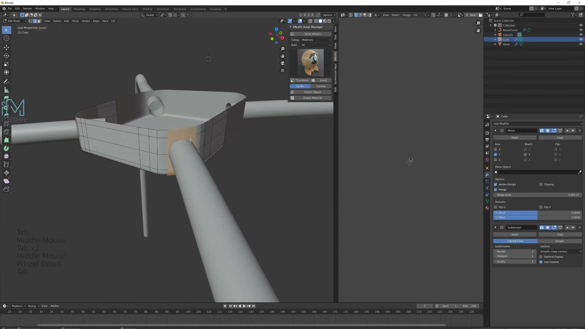
Drop in extra loops with Ctrl+R around the edges you want to keep sharp: one near each outer corner of the block, plus a couple around the inset recess to stop subdivision from rounding the pocket into nothing. You can spin the middle mouse wheel while the loop cut tool is active to add multiple parallel loops in a single operation, although I prefer to place them individually here so each loop lines up exactly where the geometry needs reinforcing.
Right-click the object and pick Shade Smooth. The box should now read as a softly rounded block with a clean recess on its underside: every corner crisp where you placed a support loop, every long span gently curved by subdivision.
If a side still looks slightly off after shading smooth, add one more loop on that side specifically. The two halves of the mirror don't always need identical support loops because the seat geometry above can hide minor asymmetry, but it's worth a quick spin around the box in solid view to check before moving on to the leg holes.
Cut circular leg holes with Shrink Wrap
The clever bit: duplicate the box, turn off its Subdivision, add Shrink Wrap targeting the original, then use Loop Tools → Circle + Flatten to cut perfectly round holes that still follow the curved surface.
Enable Loop Tools and add Shrink Wrap
A normal circle command would deform the curved top of the connector box to make the faces round, which is the opposite of what you want. The trick to cutting a perfectly round hole that still follows the curve is to do the modelling on a copy of the box that's stuck to the original with Shrink Wrap.
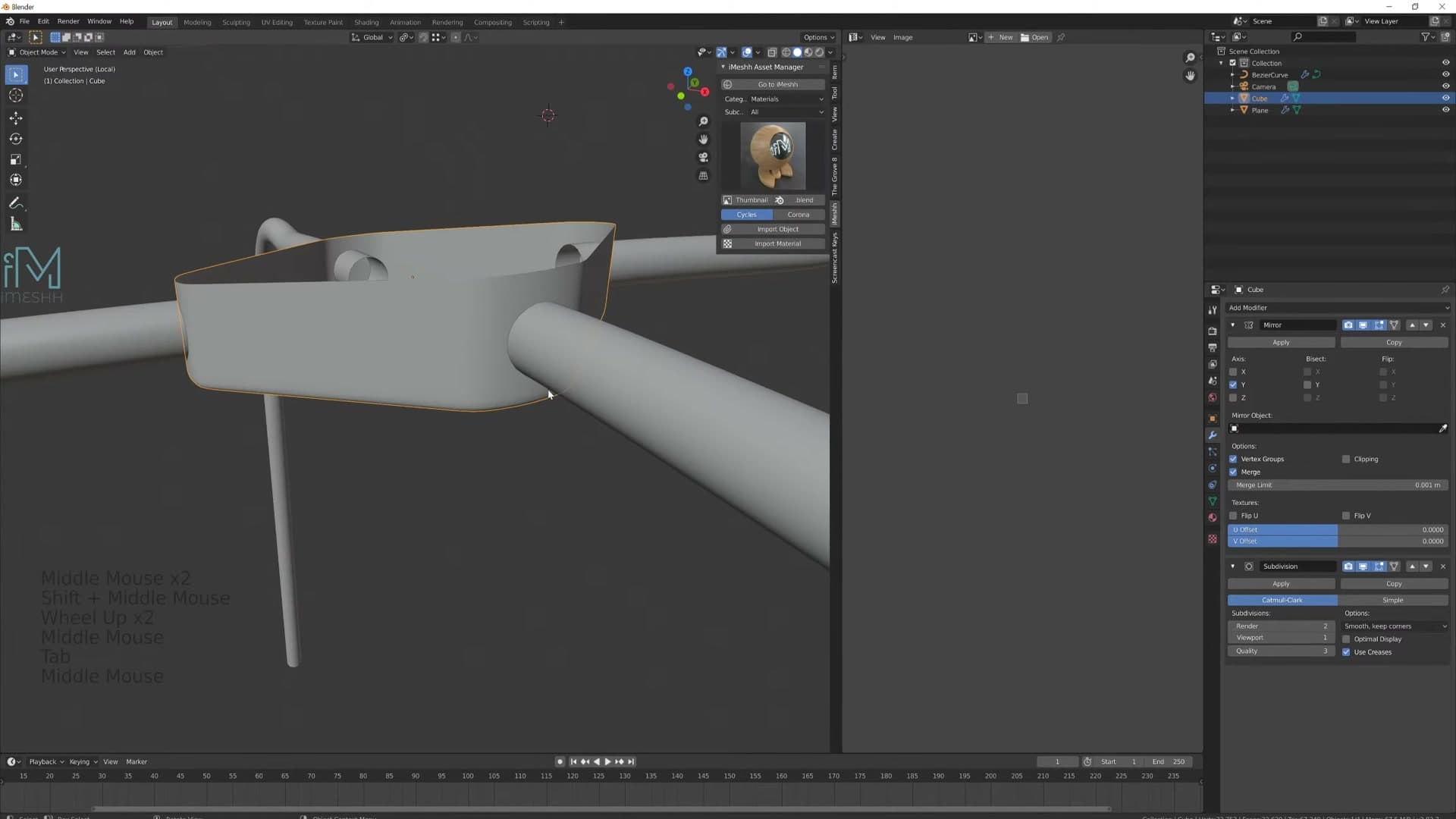
Duplicate the box with Shift+D and click in place, then on the duplicate turn the Subdivision Surface modifier off and add a Shrink Wrap modifier. In the Shrink Wrap target slot, pick the original box. The duplicate now sticks to whatever surface the source mesh defines, so any geometry you push around on it will ride the curve automatically.
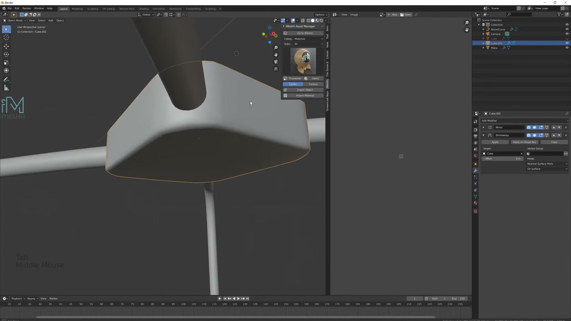
Select the source mesh and press H to hide it. You don't need to see it from here on; every edit happens on the duplicate, and Shrink Wrap quietly keeps it conformed to the hidden source underneath.
Circle and flatten the face loops
Select the face you want to turn into a hole (the inset face on top of the curved box) and run Loop Tools → Circle. The faces snap into a perfect ring, but because Shrink Wrap is still pulling them back onto the surface underneath, the ring is both round and curved with the box. If it looks a little starved or wobbly, drop in an extra edge loop or two for more geometry and run Circle again.
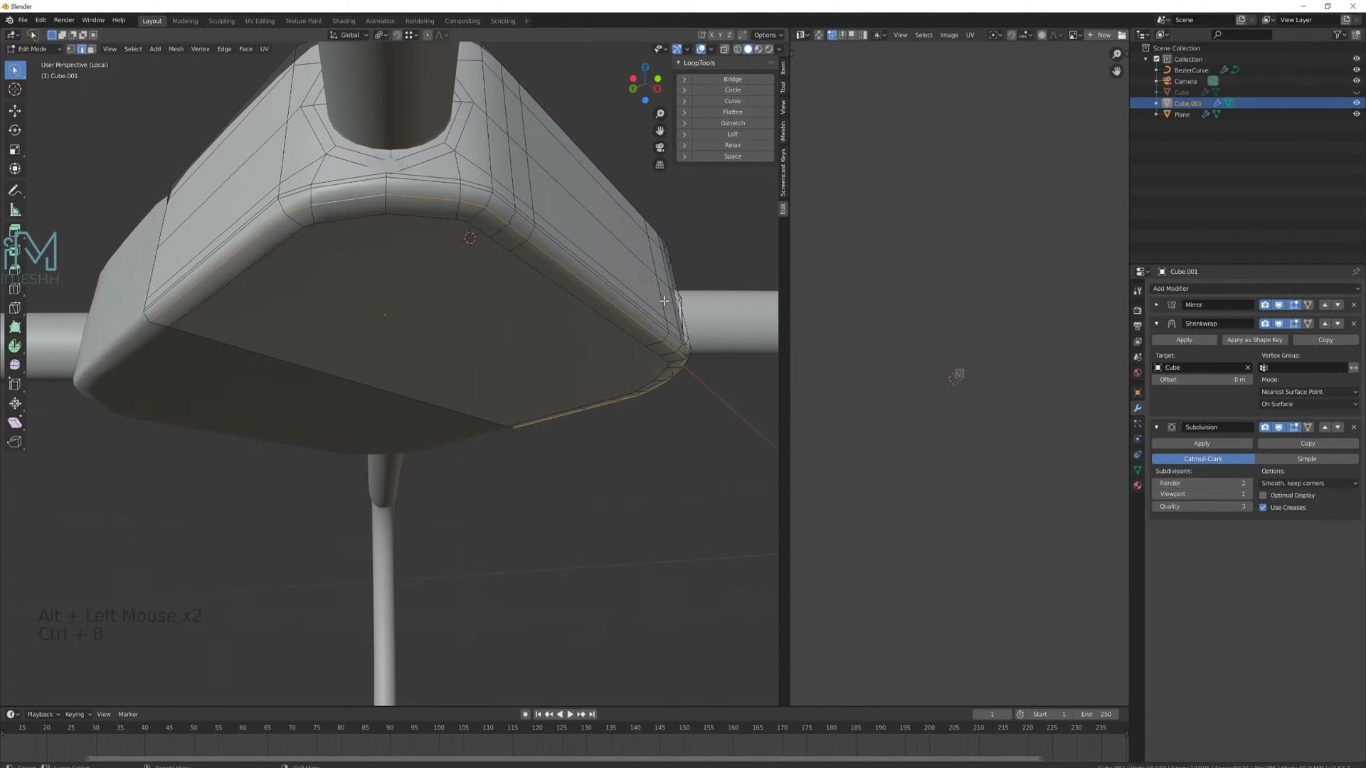
Press I to add an inset just inside the new circle. This new loop is a supporting edge. Without it, the Subdivision Surface would smooth the rim of the hole away into a soft dimple instead of holding it as a crisp circle.
The supporting loop tends to look uneven along the curve and throws some bad shading right at the seam. Select the whole loop and run Loop Tools → Flatten, then use GG (edge slide) to ease it back into a clean position. The shading along the rim should settle once the supporting loop is flat.
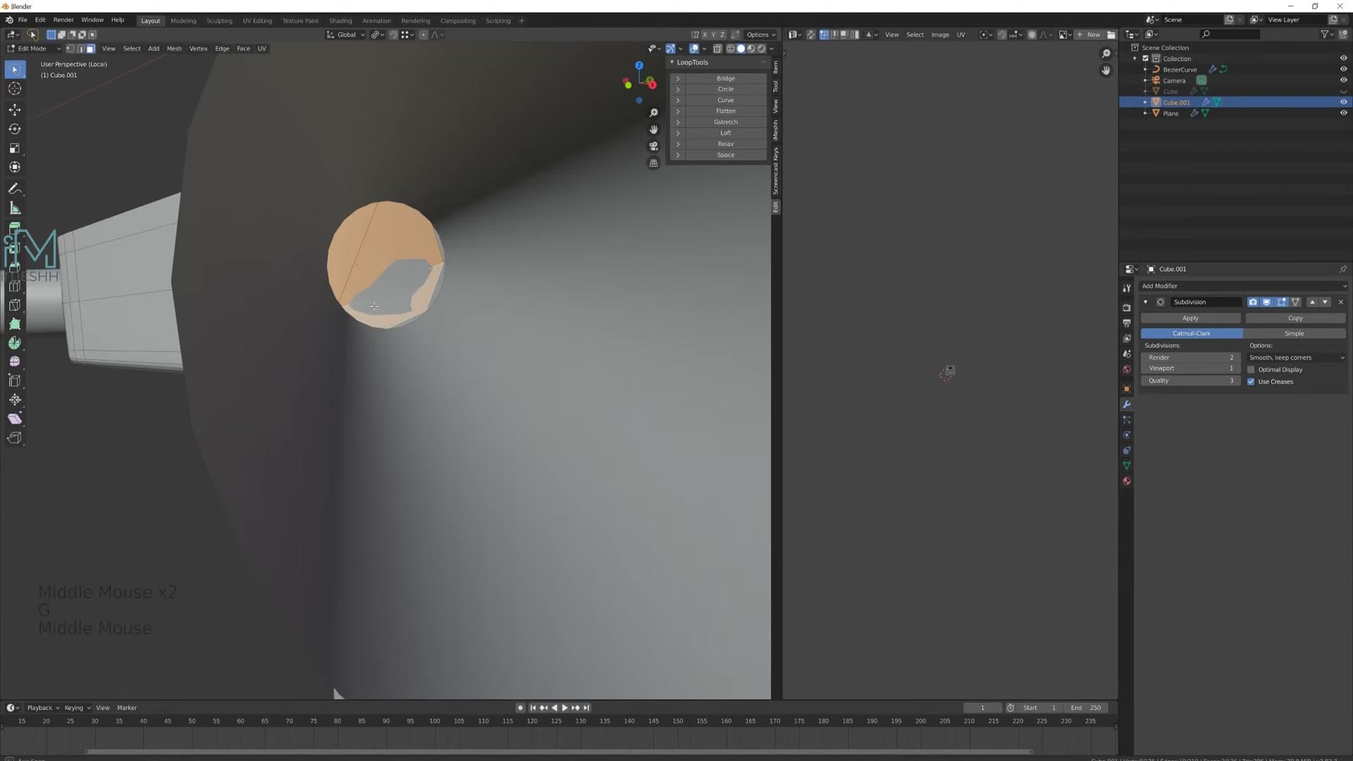
Repeat the routine on the second face you're cutting into a hole: select the face, run Circle, scale it down to size, then press I for the supporting inset. Turn Subdivision Surface back on at this point and both holes should read as crisp circles seated cleanly into the curved top of the box.
Extrude the holes inward and add the second hole
Apply the Mirror and Shrink Wrap modifiers to bake the geometry in, then delete one half of the box again so a fresh Mirror can be added later as a non-destructive working setup. With the spare half gone, select the four inner faces of the first hole and press E to extrude inward a little, then E a second time. The two stacked extrusions leave a supporting loop right at the edge of the circle, which is what holds the hole's shape under Subdivision.
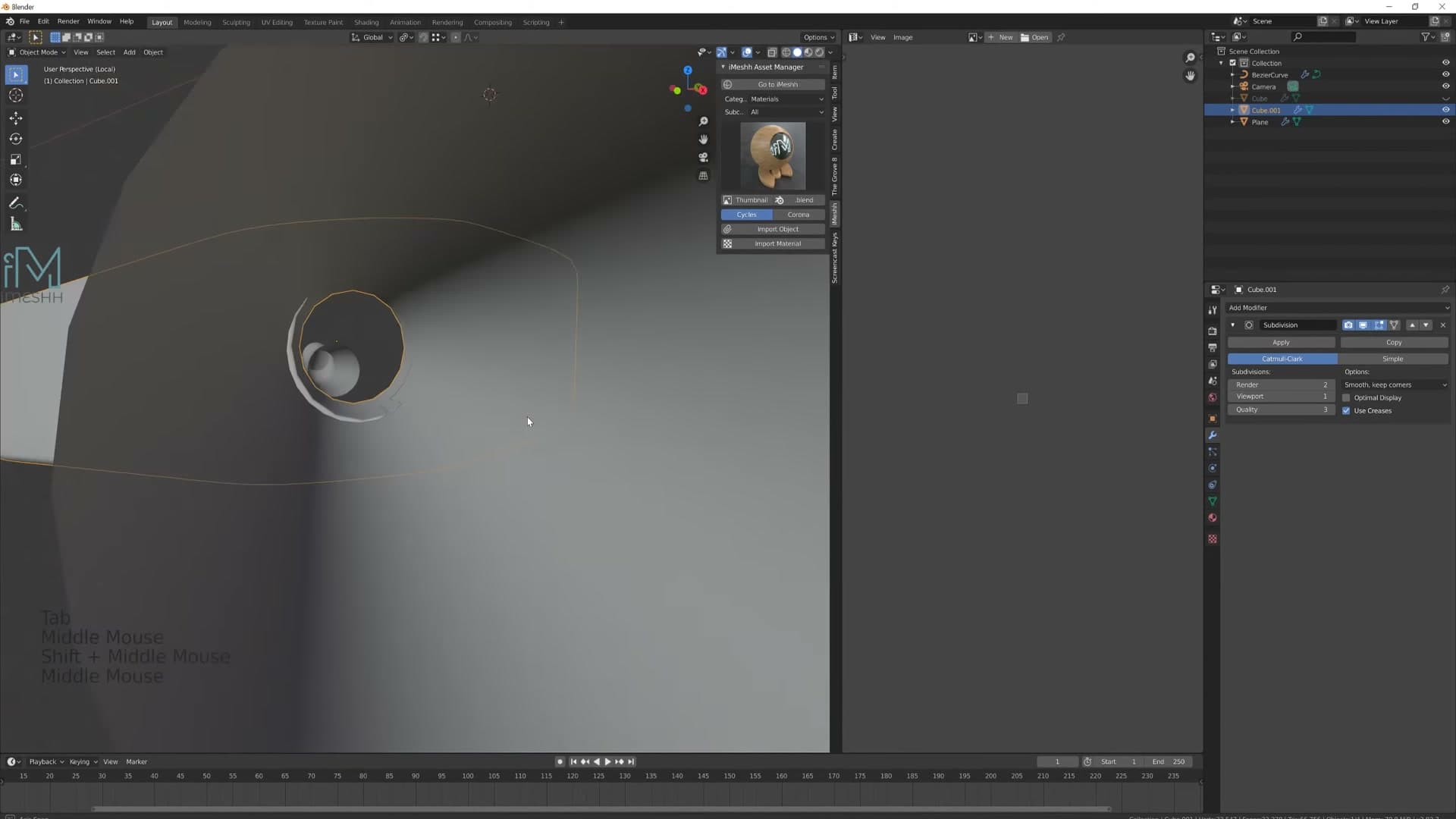
If the hole needs to be a bit larger to seat the leg, grab the inner edge loop and press Ctrl + Numpad + a couple of times to grow the selection by one ring at a time, then scale it up just a touch. Where the leg curve is now poking through the rim, slide the curve back into the centre of the circle. The inside of the hole doesn't need to be watertight. The leg sockets straight in and disappears, so the geometry inside can be as tight as it likes.
For the second hole, select its inset faces and press E to extrude inward a little, E again to push it deeper, then X → Faces to delete the cap and leave an open socket. Move the second leg curve so it sits centred in the new hole. Adding another Subdivision Surface pass smooths the fresh geometry; if it surfaces an overlapping face, select everything and run Merge by Distance (the renamed Remove Doubles) to clear out any duplicate verts.
Finish the box with a Mirror modifier set to Y and turn on clipping. Both leg holes now propagate from the half you actually worked on, perfectly aligned along the centre seam. One piece of work, both sockets in place.
Add the underside brace and Bolt Factory screws
A cylindrical brace links the legs underneath, then the free Bolt Factory add-on drops in Phillips-head bolts in seconds. Small details like this sell the realism.
Model the cylindrical support brace
With the leg connectors finished, the chair needs a horizontal brace running between them under the seat. The reference photo doesn't show how the brace attaches, so my working assumption is that it's screwed in from underneath. Start with the brace body. Add a cylinder with Shift+A, lift it up to roughly the right height, scale it down and rotate it so it lies flat along the X axis between the two leg blocks.
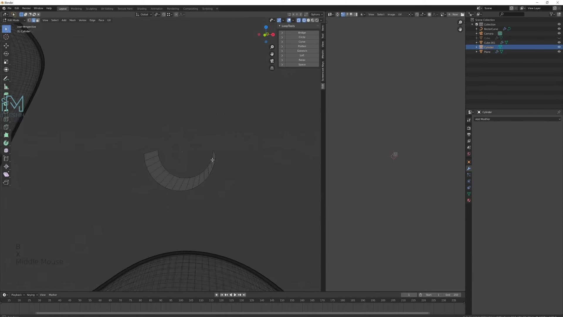
Knock off the end-cap vertices to open the cylinder up, then select the open edge ring and press E followed by S to extrude and scale in one move. Switch the pivot to Median Point so the new edges grow out from the ring's centre, and lock the scale to X so the brace stretches sideways rather than flaring outwards.
Add a Subdivision Surface modifier (one or two levels is plenty) to smooth the form, then cut a loop down the middle and scale it on X to give the brace a softly rounded profile. Drop a couple of extra vertices at each end, select the corner pairs and press Ctrl+Shift+B for a vertex bevel. Click and drag, then click again to round the ends off into perfect circles using Loop Tools' Circle option.
Solidify the brace and align it to the legs
Add a Solidify modifier to give the brace real thickness, then run Ctrl+A → Scale so the modifier reads the geometry correctly. Press X → Faces to clear out the open back face left behind by the deleted end caps. To crisp up the corners without flattening the rounded ends, stack on a Bevel modifier set to Limit Method → Angle with the angle at 85°. Only the genuine 90° corners get bevelled; the curved sections stay untouched.
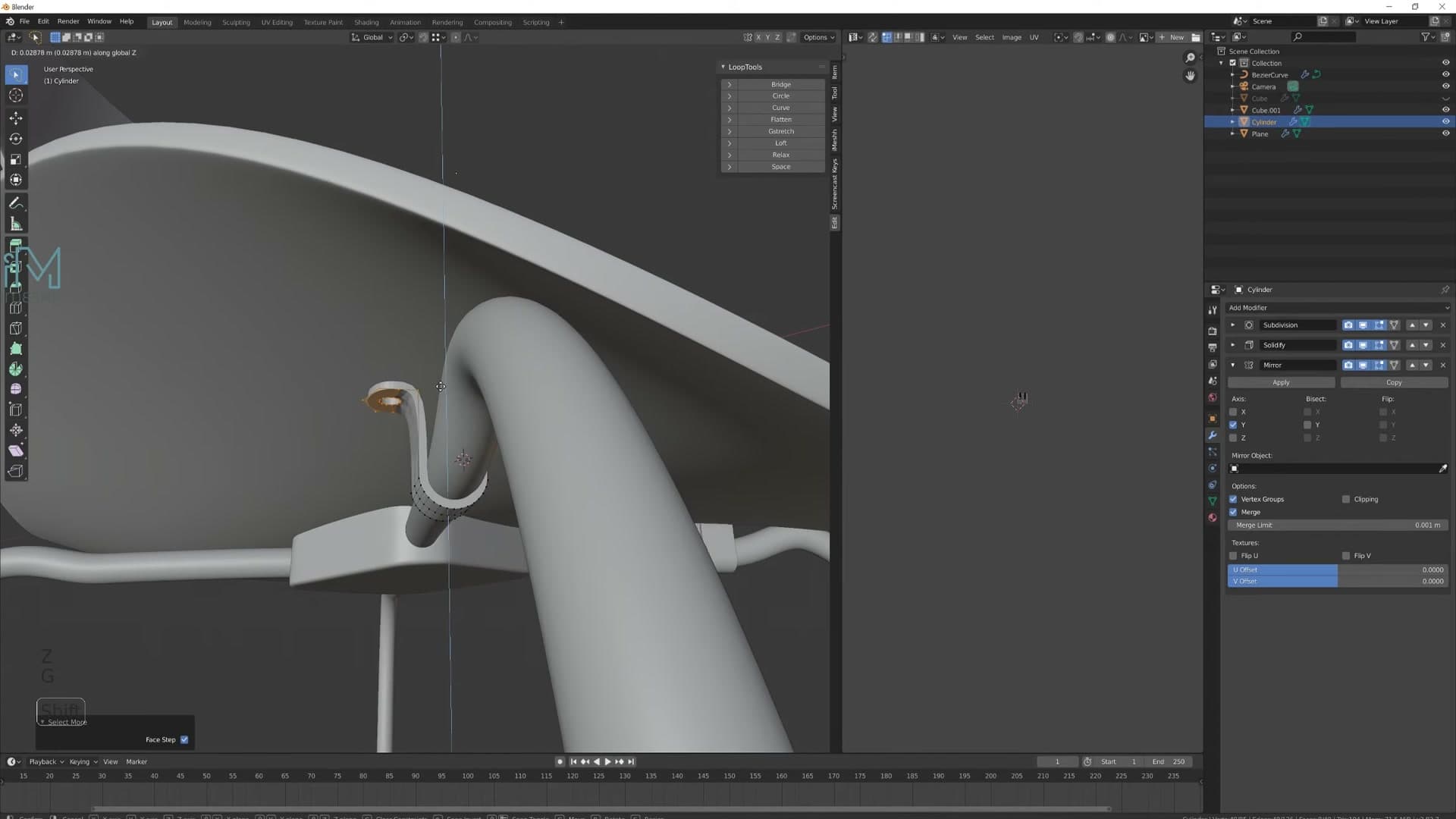
Reuse the mirror trick from earlier in the build to get a matching brace on the other leg. Drop into edit mode, grab the whole brace, slide it across so its working half sits cleanly to one side of the chair's centre line, and add a Mirror modifier. The brace now duplicates across the Y axis as you adjust it.
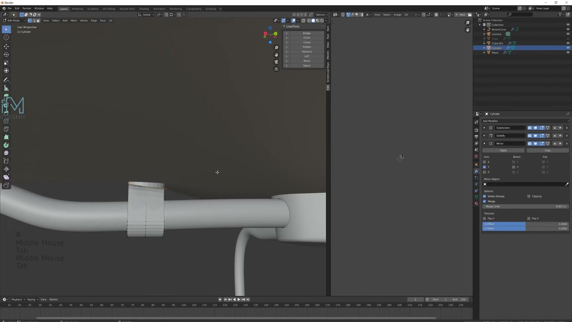
Slotting the brace ends into the leg connectors is mostly eyeball work because the original plans don't show the join clearly. Select the end cap vertices, then press Ctrl + Numpad + a couple of times to grow the selection until you have the whole rounded tip. Move and rotate it with R until it lands flush against the leg connector. Right-click and choose Shade Smooth when both ends are in place.
Add Phillips-head bolts with Bolt Factory
Bolt Factory ships with Blender for free but isn't enabled out of the box. Open Edit → Preferences → Add-ons, type bolt into the search field, and tick the box next to Bolt Factory. From here on, Shift+A → Mesh → Bolt drops in a parametric screw with all of its settings exposed in the operator panel.
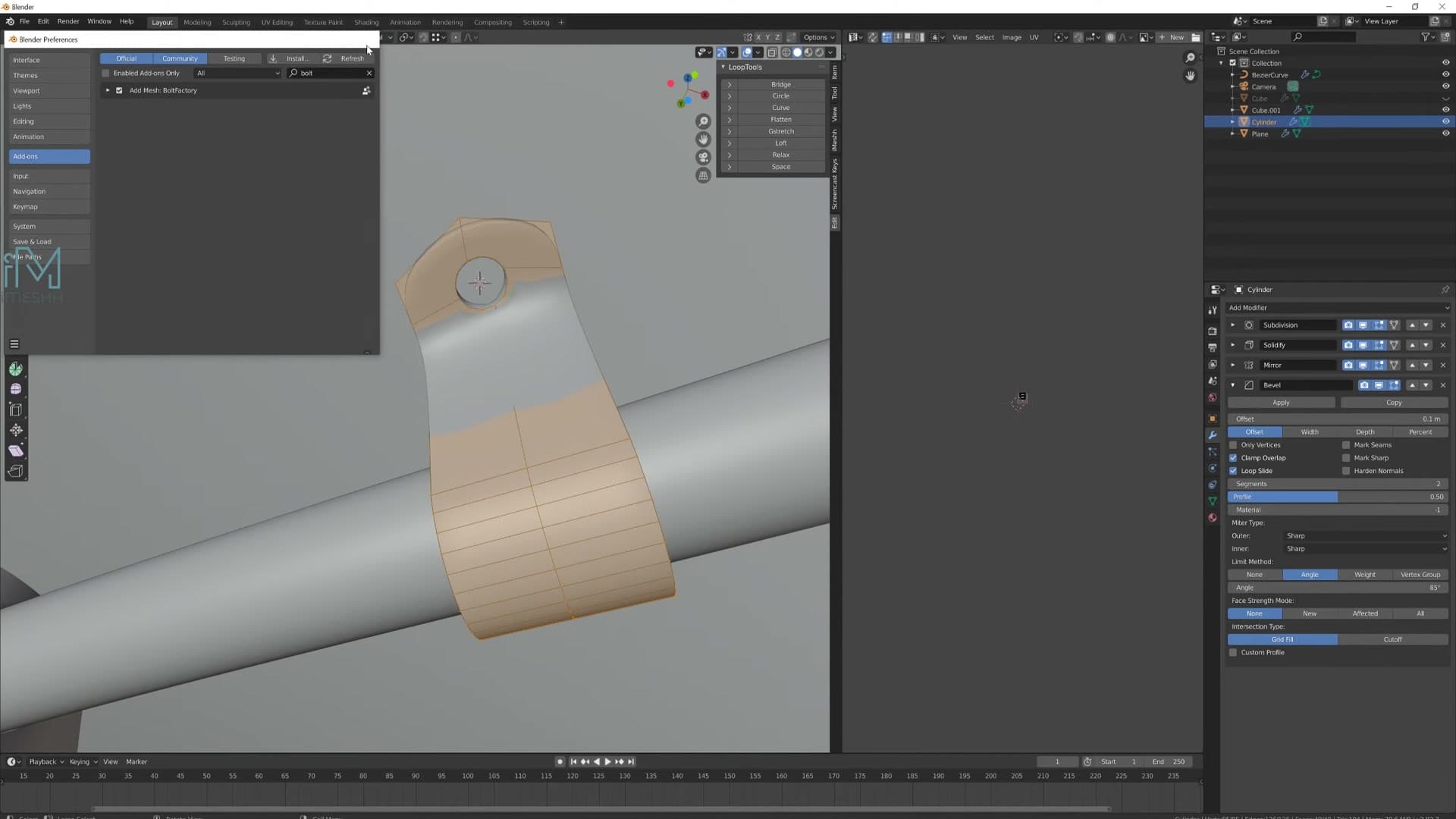
The default bolt is far bigger than anything you'd put in a chair, so shrink it down straight away. In the operator panel, set the model type to Bolt, the bit type to Phillips, and the head to Dome. That combination reads instantly as a furniture fixing without you having to model a single screw thread by hand.
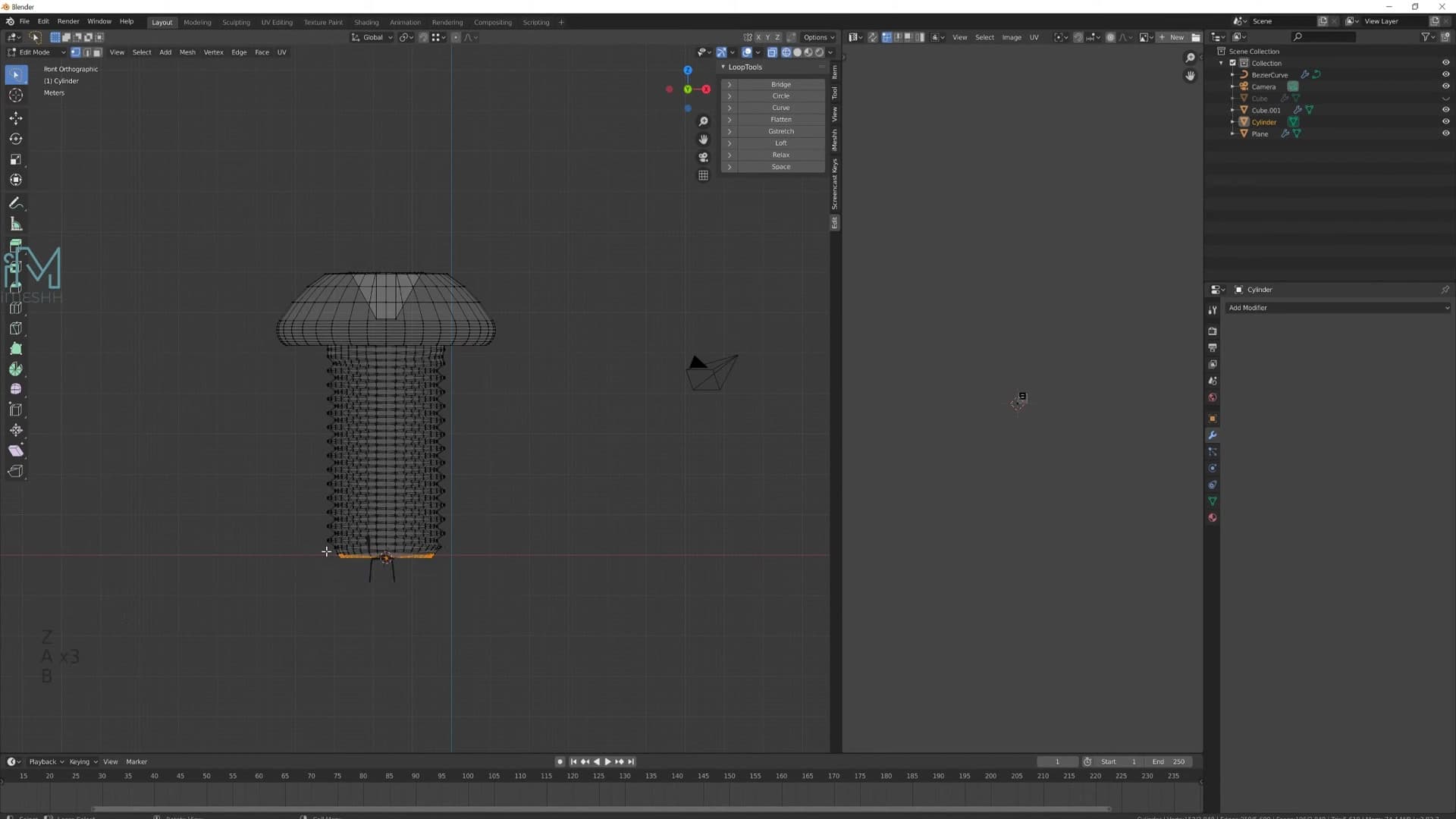
You only need the visible head. The long threaded shank stays hidden inside the leg connector, so there's no point keeping it. Drop into edit mode, select an edge loop near the base of the head and press Ctrl + Numpad + repeatedly to grow the selection down the thread until you've caught all of it. Press X → Faces to delete, then scale what's left right down and slide it into position over the first leg hole.
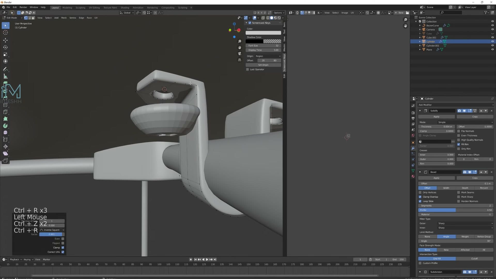
Duplicate the bolt for each remaining hole position. On the underside copies, use R X 180 to flip them so the heads point the right way. As the bolts get smaller they tend to disappear into the chair, so press Numpad . (Frame Selected) whenever you need the viewport to snap back to whichever bolt you're working on.
Convert legs to mesh and add rubber feet
Once the leg curves look right, convert them to mesh (keep the original curve hidden as a backup) and extrude the foot caps that will sit on the floor.
Convert the curve legs to a destructive mesh
With the leg silhouette where you want it, it's time to switch from a curve to a real mesh so you can extrude proper foot caps. The curve workflow is great for tweaking the shape, but you can't extrude polygons out of a curve. You need actual geometry to work with.
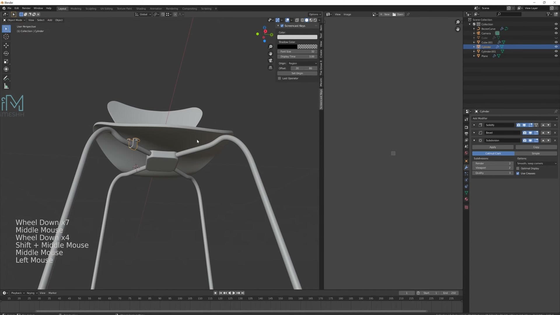
Before you commit, duplicate the leg with Shift+D and slide the copy off to one side on a single axis. You don't strictly need this backup, but it costs nothing and means the editable bezier is still tucked away in the scene if you decide to rework the bow of the leg later. Hide the original in the Outliner so it doesn't get in the way.
Select the working copy and choose Object → Convert → Mesh. Before you click, make sure the Subdivision Surface modifier is turned off. If it's on, the conversion bakes the subdivision into the geometry and you end up with a dense, hard-to-edit mesh. You can always add subsurf back as a modifier once the conversion is done.
Extrude and shape the foot caps
Converting to mesh tends to drop the Mirror modifier reference, so the first thing to check once the leg is a mesh is that both sides are still updating together. If only one leg is responding to edits, delete any stale mirror and add a fresh Mirror modifier to the new mesh.
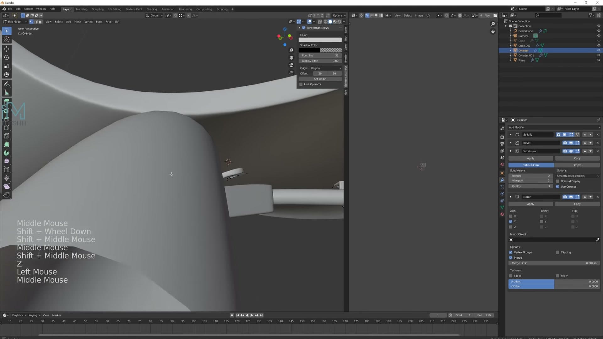
Drop into Edit Mode, select the bottom face of the leg and flatten it perfectly with S → Z → 0. That zeroes the Z scale on the selection, giving you a clean horizontal face to build from instead of the slightly tilted cap the curve left behind.
Now switch the transform pivot to Individual Origins so both legs grow feet simultaneously rather than scaling around a shared centre point. Then build the foot in a quick sequence of operations: E to extrude outwards, S to widen the new ring, E then Z to push it downwards, E then S to taper it back in, and finally F to fill the open base.
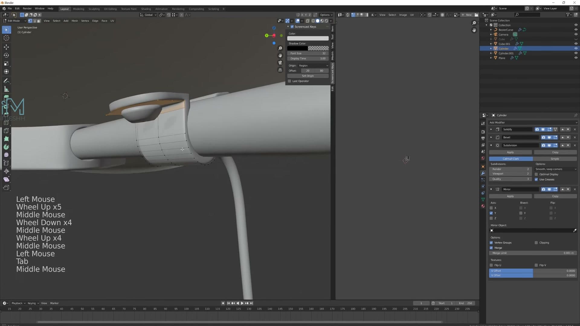
If you have proportional editing on, turn it off before you go any further. When you flatten the foot loops with S then Shift+Z you want a precise scale on the X and Y axes only. A soft falloff would drag the rest of the leg with it and ruin the silhouette.
Bevel and smooth the feet
With the basic foot block in place, jump into edge select and grab the two horizontal loops where the foot meets the leg and where the foot meets the floor. Hit Ctrl+B and bevel both at once. A small bevel is what stops the foot reading as a hard plastic block.
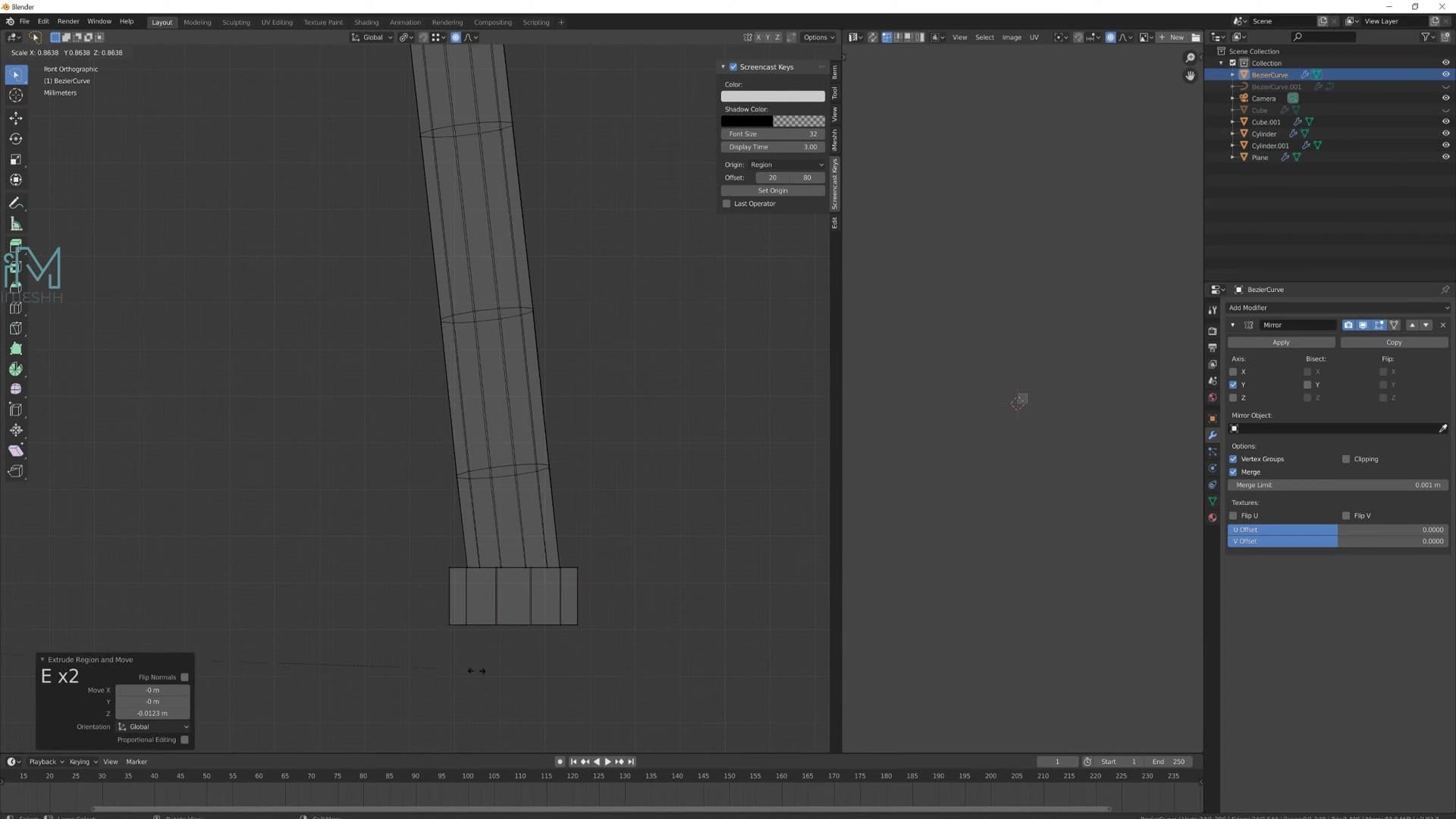
Add a Subdivision Surface modifier and right-click → Shade Smooth. The feet immediately go from a chunky extrusion to something that reads as a soft rubber pad sitting under the leg.
View the chair from the side at this point. The first pass of feet often looks a bit odd because the loops aren't sitting on the same axis as the bow of the leg. Undo the bevel, nudge the side loops over so the foot follows the natural curve of the leg, and double-check that you have the loops on both the front and back of the leg selected before you scale anything down.
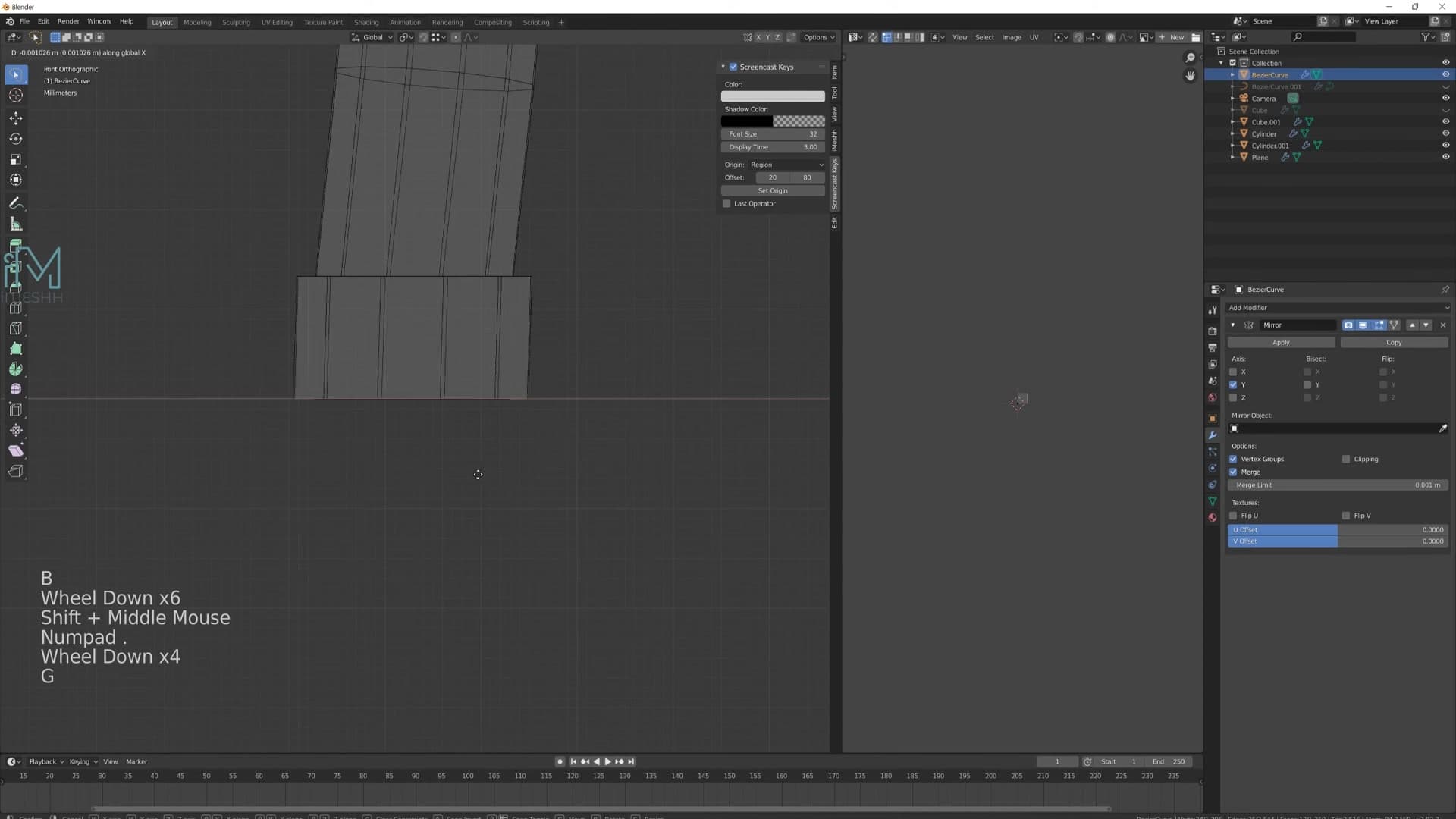
Once the silhouette looks right from every angle, reselect the same edges, run Ctrl+B again to put the bevel back, then re-apply Shade Smooth and Subdivision Surface. The feet should now follow the bow of the legs rather than sticking out at an unnatural angle. Small details like this don't take long, but they're the kind of layered touch that really sells the model.
Materials, world and camera
Bulk-link materials with Ctrl+L, drop in an HDRI for environment lighting, then set up a square camera with a low focal length for that flat product-shot look.
Apply materials with the iMeshh Asset Manager
With the modelling done, you can finish the chair with some quick texturing. I use the iMeshh Asset Manager along with the default material pack that ships with it, which makes assigning materials a one-click affair. If you don't have the Asset Manager you can still follow along by building equivalent materials in the Shader Editor. The principle is the same; you just lose the click-and-import convenience.
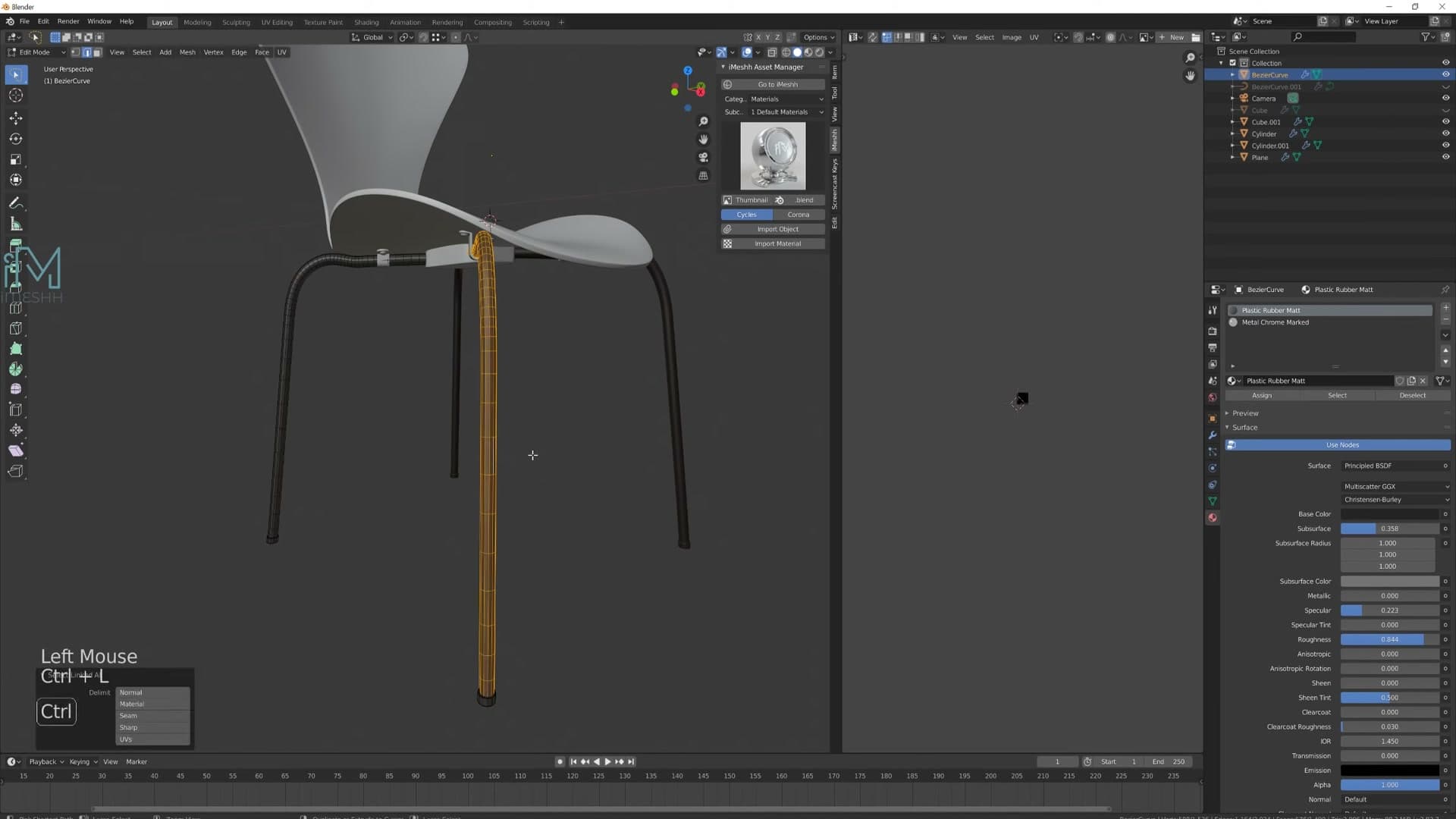
Plan the look in three buckets: the feet will be rubber, the legs will be chrome and the seat shell will be wood. In the Asset Manager, pick each material in turn and hit Import Material so they all sit in your blend file ready to be assigned.
Now apply them in bulk rather than one piece at a time. Select all the feet in the Outliner, then in the Properties panel pick the rubber material on one of them. With the rest still selected, press Ctrl+L and choose Materials. Every selected object inherits the active object's material in a single shot. Repeat for the chrome legs and the wooden seat.
When you're flying through the parts you'll occasionally spot something odd: a piece that didn't get its material, or a shading break where two objects weren't joined properly. Don't get sidetracked fixing them mid-pass; note them mentally, finish the materials sweep, and clean up afterwards.

Add an HDRI environment and floor plane
To give the chair something to reflect and sit in, open the World tab in the Properties panel and add a new Environment Texture. Load any HDRI you like. The iMeshh pack ships with a few, but anything from your library that gives soft directional light will work for a product-style preview.
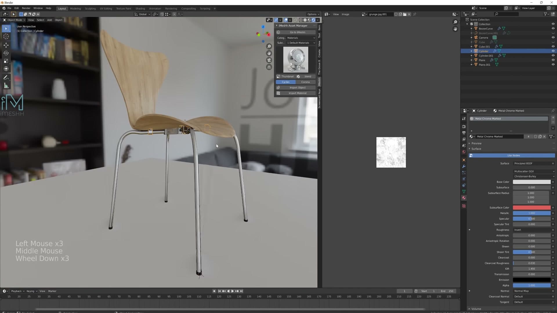
Switch the viewport to Shift+Z → Rendered so you can see the lighting and materials together. If you're previewing in Eevee, head into the Render properties and enable Ambient Occlusion and Screen Space Reflections. Both are off by default and both make a big difference to how solid and grounded the chair looks in the viewport. The AO darkens contact points like where the feet meet the floor, and SSR lets the chrome actually pick up the environment around it.
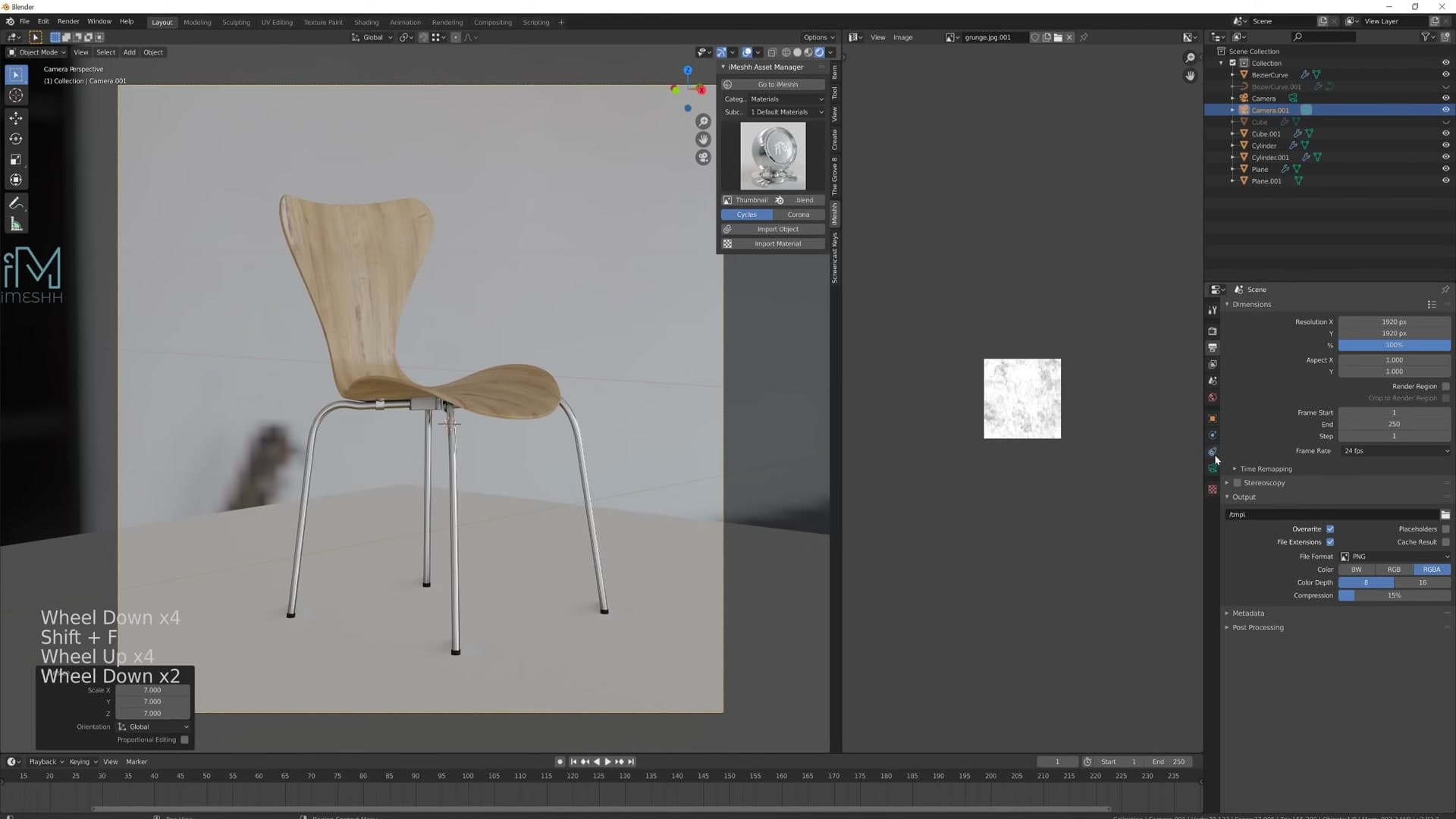
Finally, give the chair a ground to stand on. Shift+right-click to drop the 3D cursor at the feet, then add a plane there and scale it up. That's enough to catch the AO shadow and reflect a hint of the chair back into the chrome.
Set up a square camera with a low focal length
For final renders I like to set up a deliberate camera rather than just pressing Ctrl+Numpad+0 from the viewport. Add a camera, frame the chair in the centre and then head into the camera's Object Data properties.
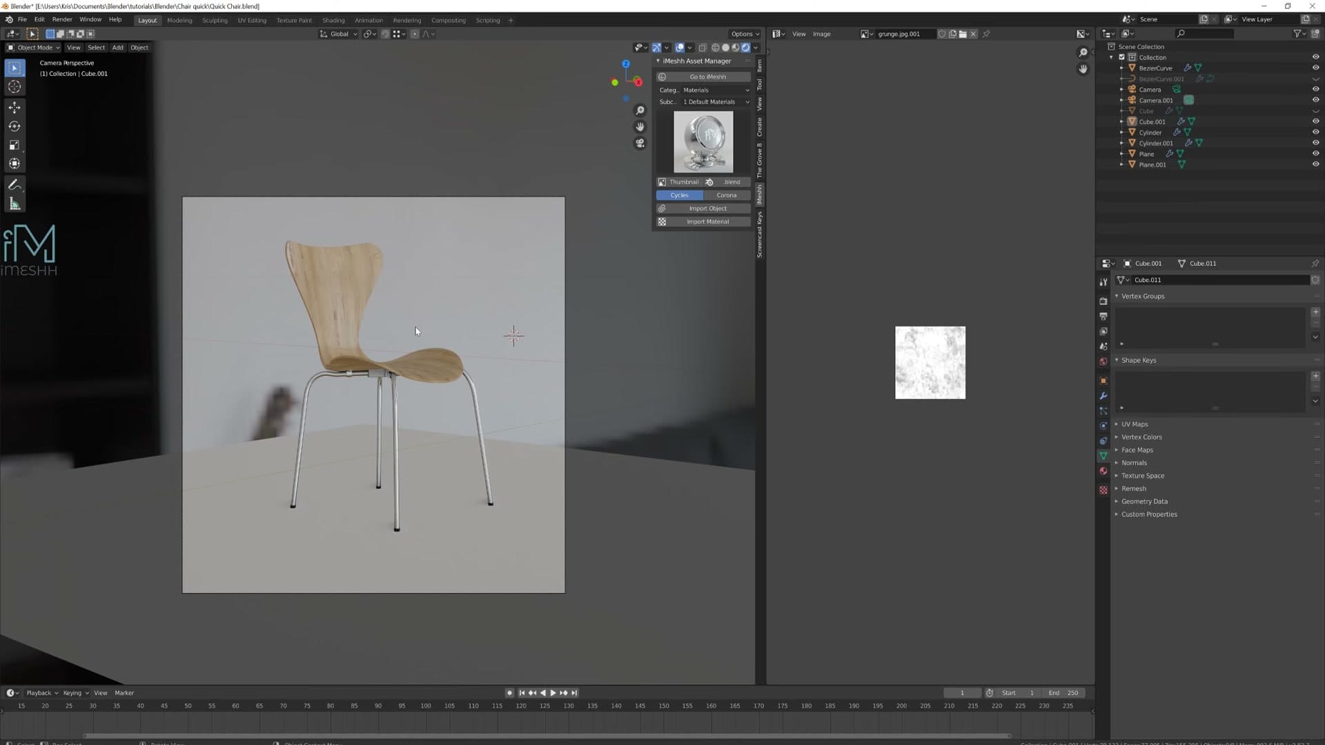
The trick is to use a low field of view (around 30), which flattens the perspective and gives the render an almost orthographic feel. Strong perspective is great for architectural shots where you want to show depth; for a single product like a chair it tends to distort the proportions and pull the nearest leg forward unnaturally. Dialling the FOV down compresses the chair back into its true silhouette.
Set the render output aspect to square. A 1:1 frame works beautifully for product shots and reads cleanly on social and portfolio grids. Move the camera back until the chair sits comfortably inside the frame, with a little breathing room top and bottom.
From this angle the layered detail pays off: the bolts on the connector box, the rounded feet, the holes punched cleanly through the curved metal, the slight bevel catching the HDRI on the seat edge. None of those details took long individually, but together they make the chair look made rather than modelled.

That's the full build: a chair from one reference photo, using a mirrored plane for the seat, bezier curves for the legs, shrink-wrap for the holes and Bolt Factory for the screws. Same recipe scales to most furniture. Block the big shape first, layer in the medium details, finish with the small ones.
Tools and credits
Everything mentioned in this tutorial, with links.
- Blender (the renderer this entire build runs in).
- iMeshh studio platform (project management, client review, asset library, invoicing). The asset library used in this tutorial is included with every iMeshh Pro plan.
- Poly Haven (free CC0 textures and HDRIs).
Pillar guide: Modelling hub