Setting up the project and reference photos
Kris introduces the project - a real chair from his apartment he's been meaning to remodel - then photographs it from multiple angles and loads those photos into Blender as reference images. He scales and positions the side, front, and back photos so they can act as tracing guides, then dims their opacity later when they start drowning out the model.
Face reveal and project intro
This build started because of a chair that had been sitting in Kris's apartment for the better part of six months, quietly nagging him to be remodelled. With finally a bit of time on his hands, he decided to recreate it in Blender from scratch and record the whole process, including a rare face reveal at the top of the video.
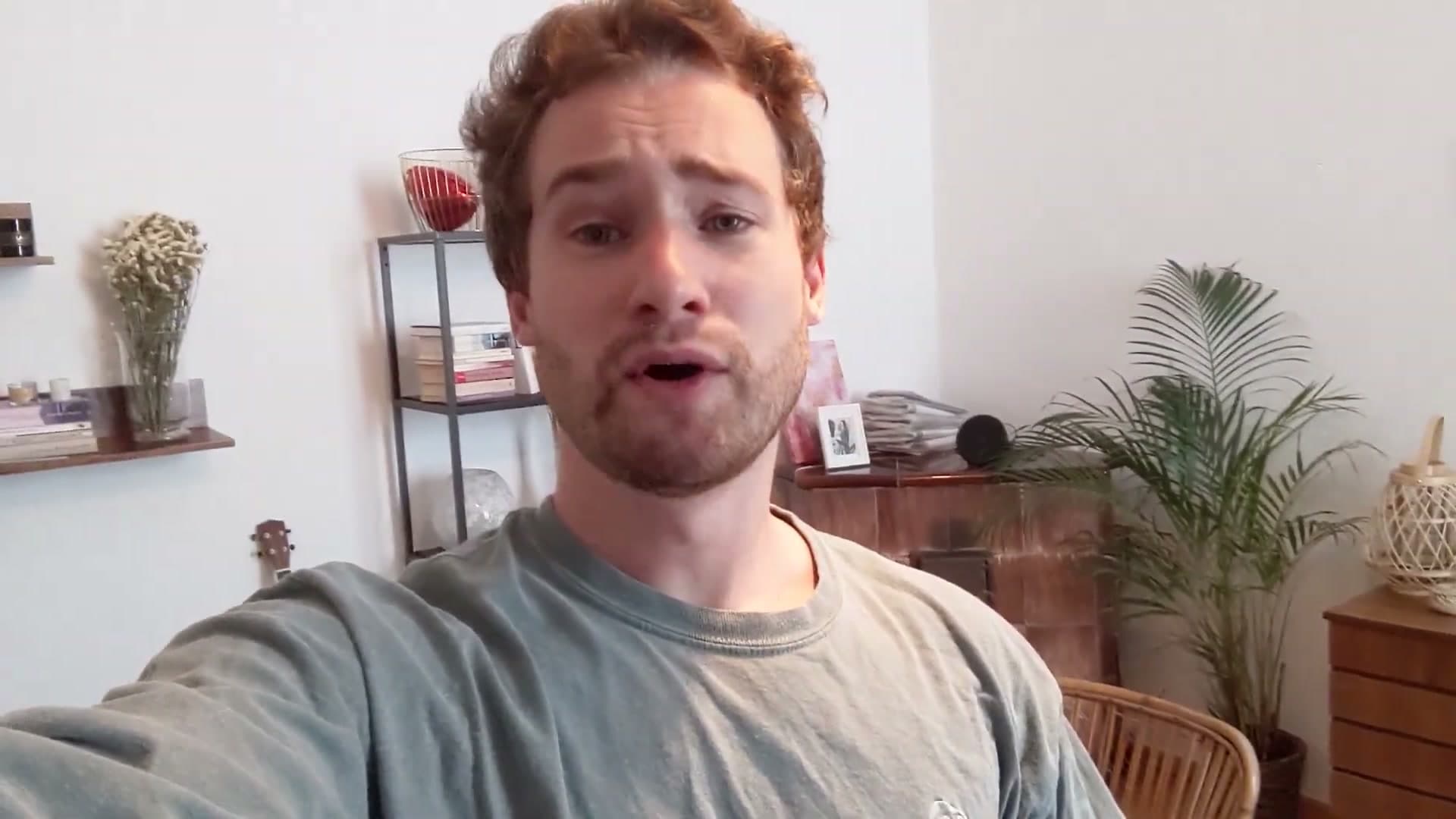
The premise is simple: if you have a piece of furniture you've always wanted to model, this walkthrough is the template. You'll photograph the real object from multiple angles, pin those photos in the Blender viewport as tracing guides, then build the frame from Bezier curves. The reference photos used in this tutorial are also available to download so you can follow along on the same chair.
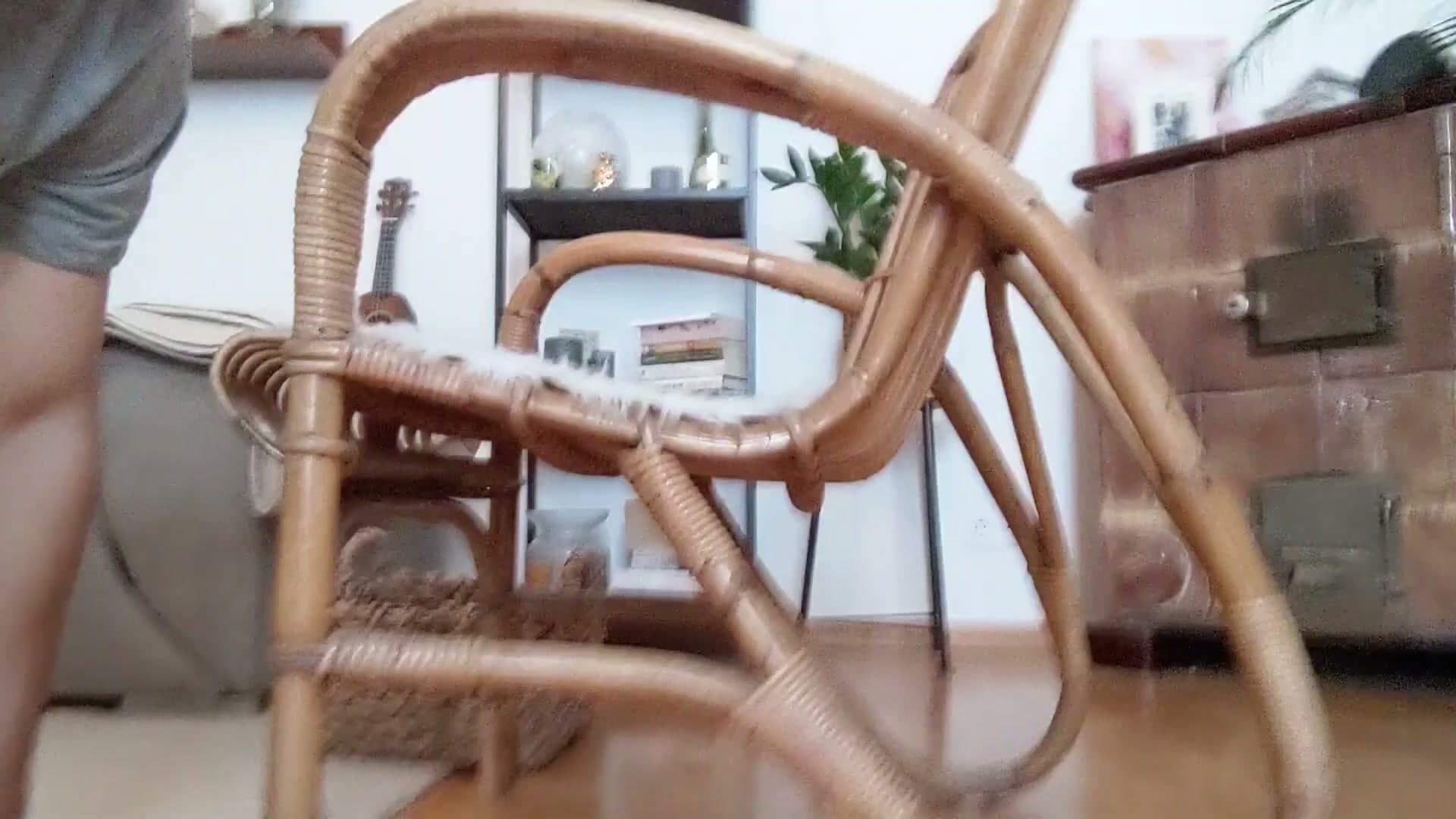
The chair itself is a curved bamboo-style piece: organic, asymmetric, and full of the kind of subtle bends that make a freehand CAD approach painful. That's exactly the sort of subject Bezier curves are good for, which is why the entire build hinges on them rather than box modelling.
Loading and aligning side, front, and back photos
Save the project first, then load the photographs as reference images directly into the viewport. You're aiming for three angles to start with (side, front, and back), each pinned in roughly the right orientation around your origin.
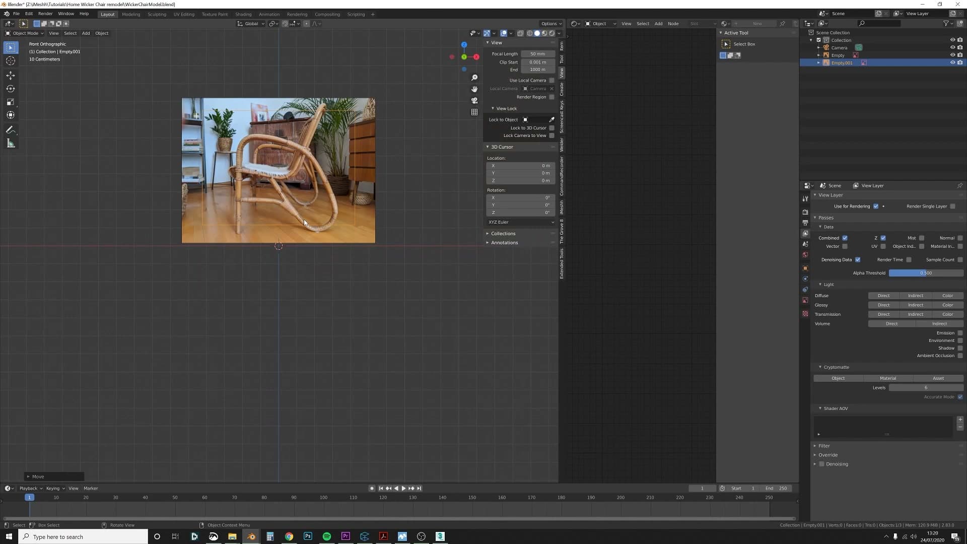
Once they're loaded, scale them down and position them so they sit where the chair would actually sit in 3D space. The side photo aligns to the side view, the front photo to the front view, and so on. Spend a minute getting the rough proportions to match. You'll be tracing on top of these for the next half hour.
Don't expect a perfect fit. Because the references are photographs rather than CAD drawings, every angle carries a bit of lens perspective, so the silhouette will never line up exactly the way an orthographic blueprint would. They're a guide, not a tracing template. When your Bezier frame drifts a few millimetres off the photo edge, that's the photo's fault, not yours.
Dimming reference opacity for visibility
Once you start tracing curves over the photos, you'll quickly notice the references are too bright. The dark frame of the model gets lost against the lit-up image behind it.
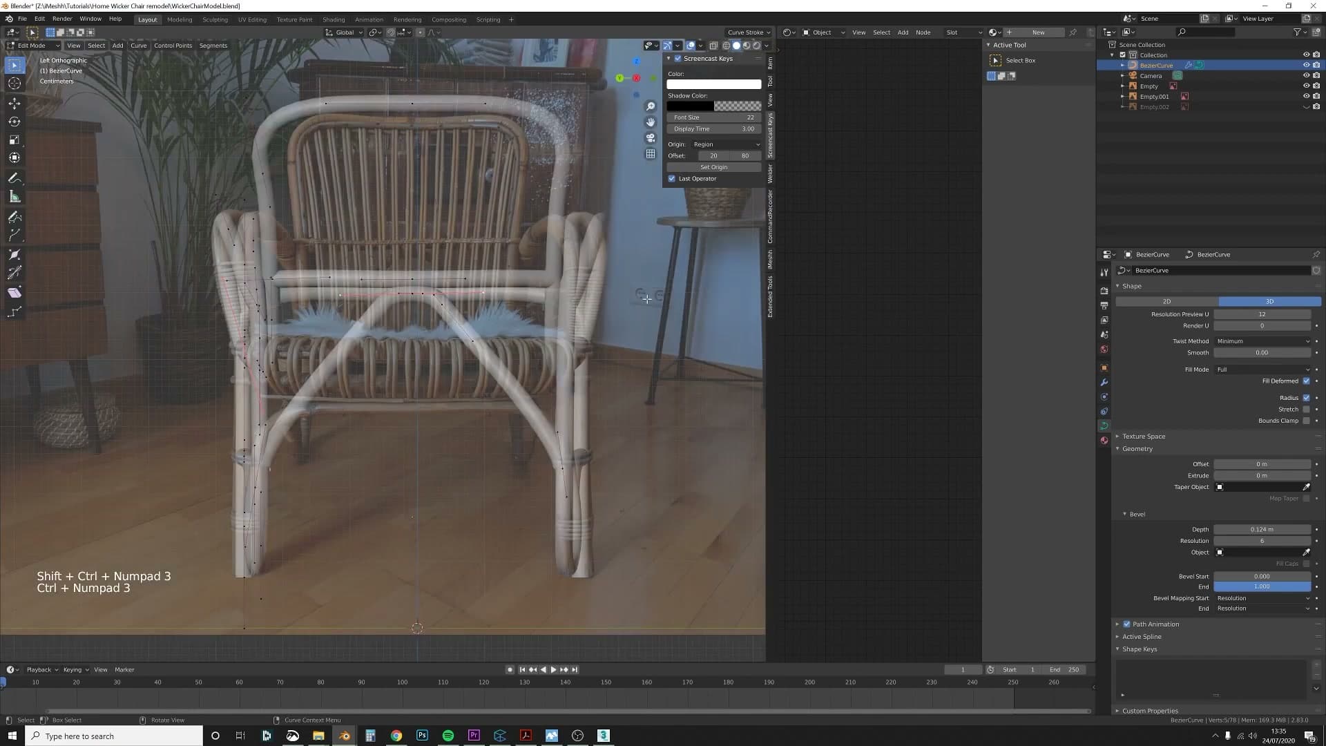
Click on the reference image to select it, open its image properties, and drop the Opacity down until the photo recedes into the background. You want it visible enough to guide your tracing, but faint enough that your curve geometry stays clearly readable on top.
Tracing the main frame with Bezier curves
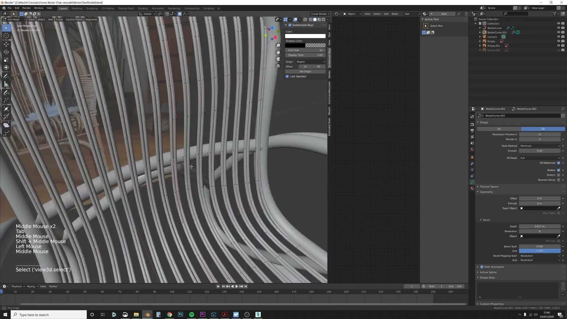
The chair's frame starts as a single Bezier curve traced over the reference photo. Kris extrudes new control points with E, rotates them into position with R, and adds bevel depth in the Geometry tab so the curve renders as a visible tube. This is the load-bearing technique for the whole build - almost every part of the chair starts as a Bezier curve with bevel geometry.
Adding the first Bezier curve and extruding control points
Add a Bezier curve to the scene, rotate it into roughly the right orientation, and drop it on top of one corner of the frame in your reference. Don't worry about matching the photograph exactly. You're laying down a guide, and the perspective in the photo means the curve will never sit perfectly on top of the photo line.
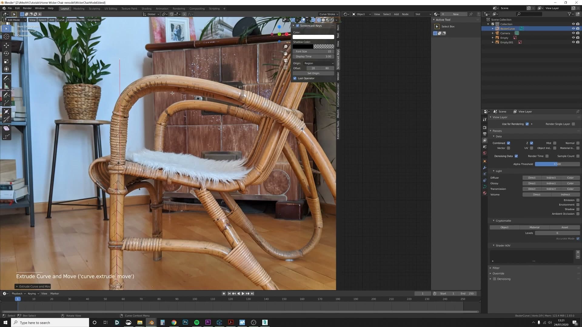
To extend the curve along the frame, click the end handle, press E to extrude a new control point, then press R to rotate it into position. Keep going point by point, working your way around the outline of the chair.
Adding bevel depth in the Geometry tab
A bare Bezier curve renders as a thin line in the viewport, which makes it hard to judge whether the shape is sitting right against the reference. To turn the curve into a visible tube, open the Object Data Properties and head into the Geometry tab and give it some depth and bump the resolution up a notch if you want a smoother profile.
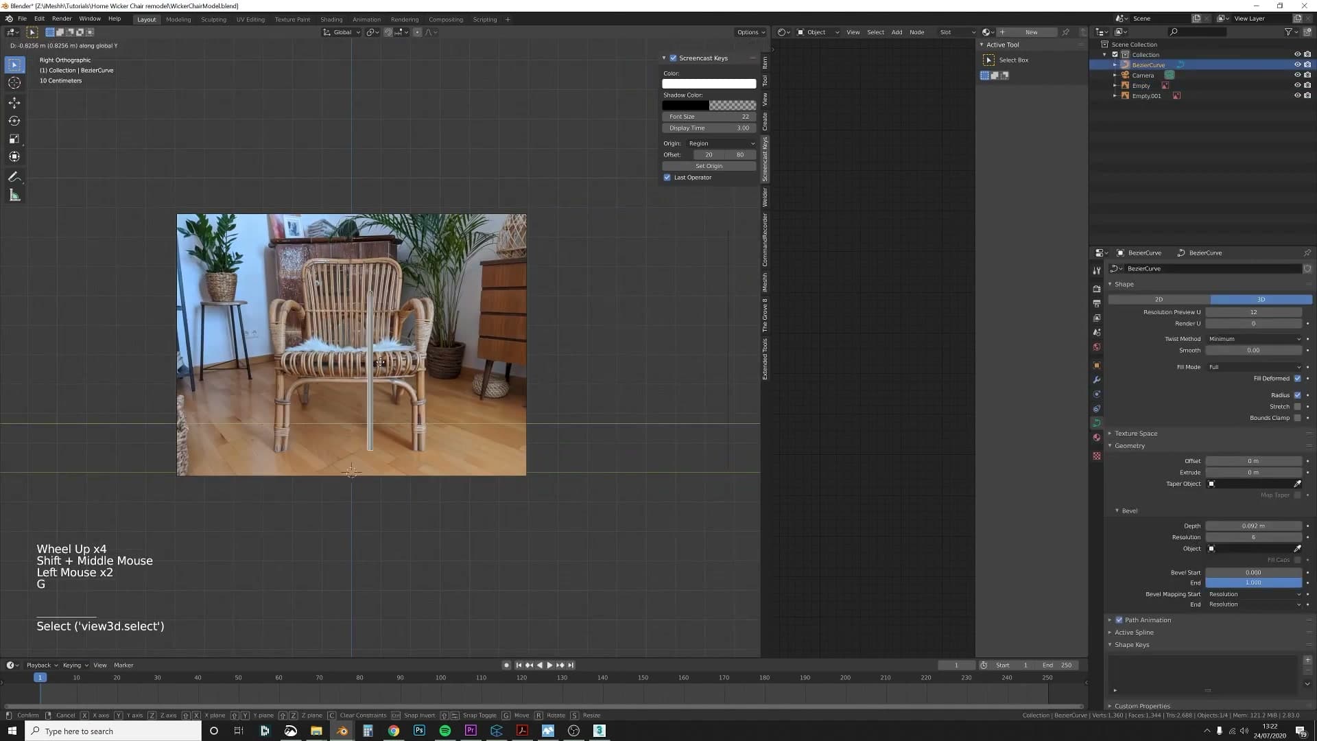
With geometry on, every extruded point reads as solid tubing instead of a wireframe sketch, so you can carry on around the frame and actually see what you're doing.
Setting the origin and adding a Mirror modifier
The chair is symmetrical, so there's no reason to model both halves. Drop into edit mode, shift the curve sideways so the object's origin sits dead centre on the chair, then add a Mirror modifier. From this point on, every change you make to one side updates the other half automatically. You only have to think about half a chair.
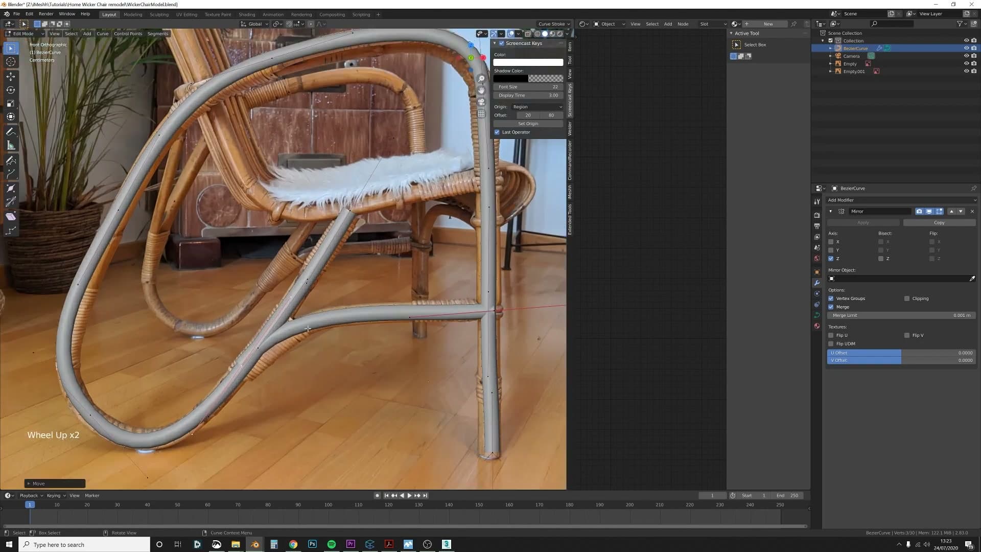
As Kris works he taps numpad 3 for the right view and numpad 1 for the front, hopping between sides as he goes. There's no functional reason to switch views constantly, but flipping between the two angles makes it easier to spot when a control point has drifted out of plane.
Shift+D and extrude to branch at junctions
When the frame branches (where two tubes split off from a single point), you can't just keep extruding the existing curve. Click on the vertex where the split happens, press Shift+D to duplicate it, then press E to extrude the duplicate outward along the new branch. From there, carry on extruding and rotating around the new section of the shape.
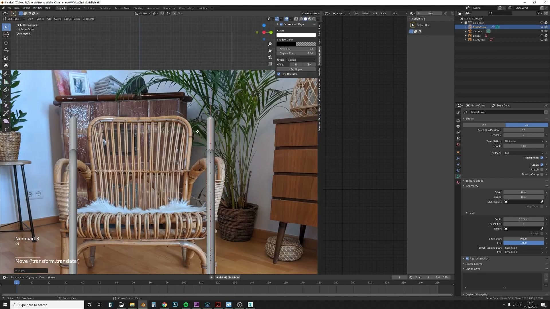
It doesn't matter at this stage if the two curves overlap or cross through each other. The real chair has its own way of hiding those junctions later, which makes the whole build much more forgiving. You can focus on getting the silhouette right rather than fiddling with perfect intersections.
The fiddliest bit is the front of the frame. Because the reference was shot in perspective rather than orthographically, the proportions don't line up cleanly with an axis-aligned model, and you'll need to nudge points around by eye. Having the physical chair sitting next to you is a huge advantage; without it, you're leaning more on artistic judgement than measurement.
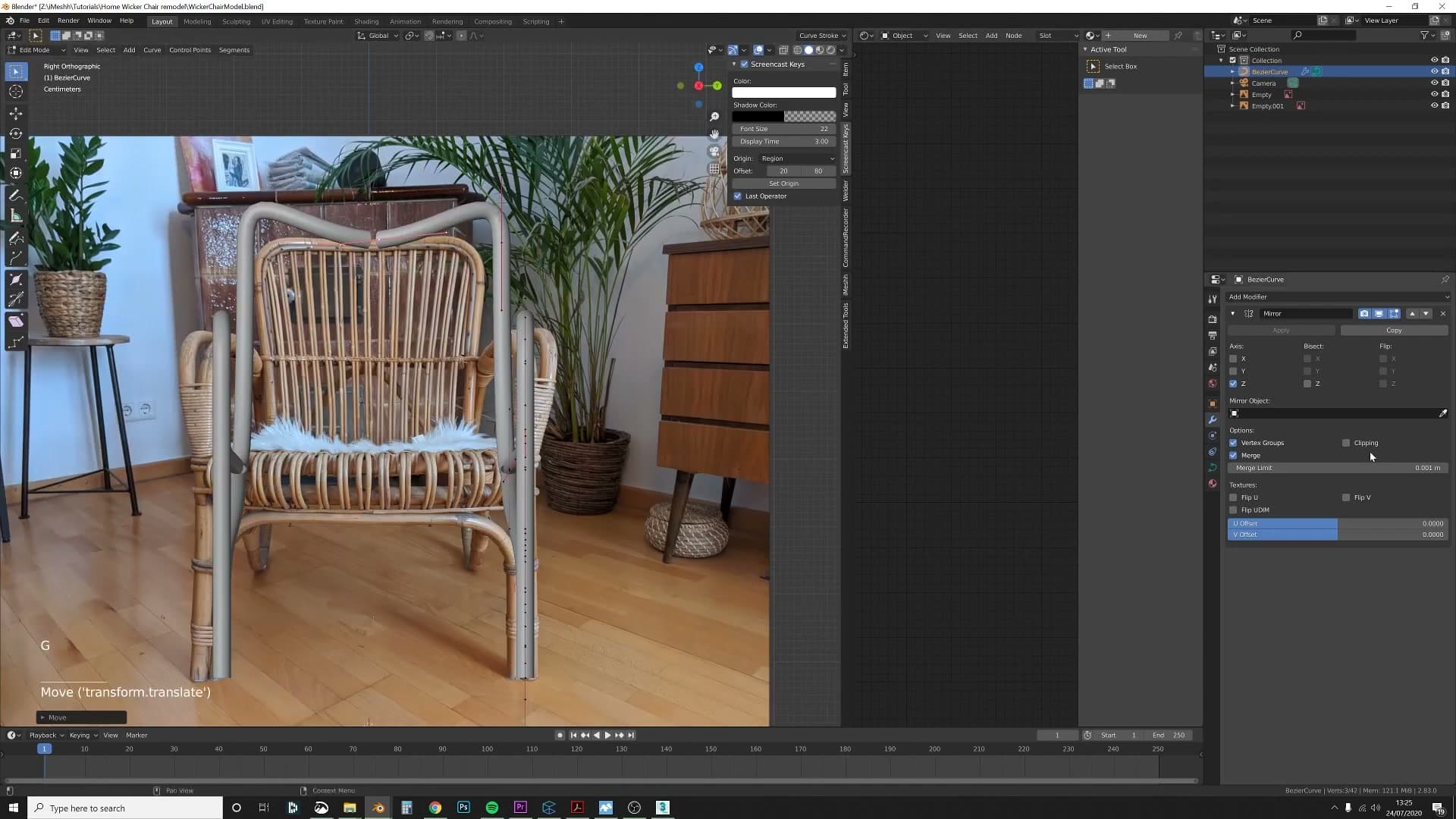
When the two branches meet at the centre, line their end points up so the Mirror modifier can merge them cleanly. The merge limit defaults to 0.001m, shown in the modifier panel on the right. If you haven't applied scale to the curve yet, the merge often won't take because the world-space distance between the two end points is larger than that limit. Apply the scale now, or leave it for later and come back to the join once the scale has been applied.
Building the back-side frame from a second reference
Once the front and sides are blocked in, Kris adds a back reference photo and hides the front one so he can concentrate on the rear curves. He builds the back frame using the same curve-extrusion workflow, again working symmetrically with the Mirror modifier.
Adding the back reference image
With the front and sides blocked in, you'll want to switch focus to the rear of the chair. Load the back photograph into the viewport the same way you loaded the side and front reference earlier - as an image empty, positioned behind the chair on the relevant axis.
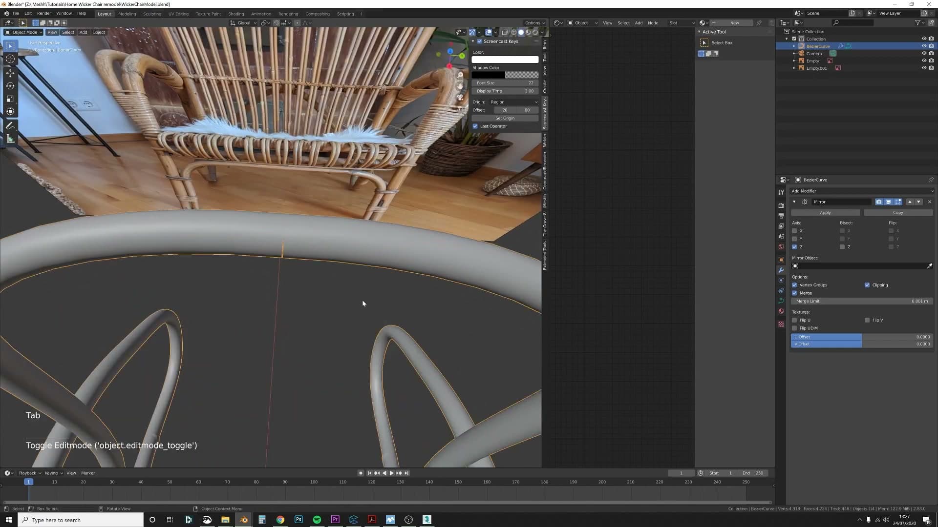
Once the back reference is in place, hide the front one so it doesn't compete visually with the new photo. You now have a clean rear view to trace against, with the side reference still available for cross-checking proportions as you work.
Tracing the back curves
The workflow for the back frame is identical to the one you used on the front. Start a Bezier curve, position it against the rear photo, then extrude points with E and rotate them with R to walk the curve along each rear upright and cross-bar. Because the Mirror modifier you added earlier is still active on the original curve, every point you place on one side appears symmetrically on the other - you're still only modelling half the chair.
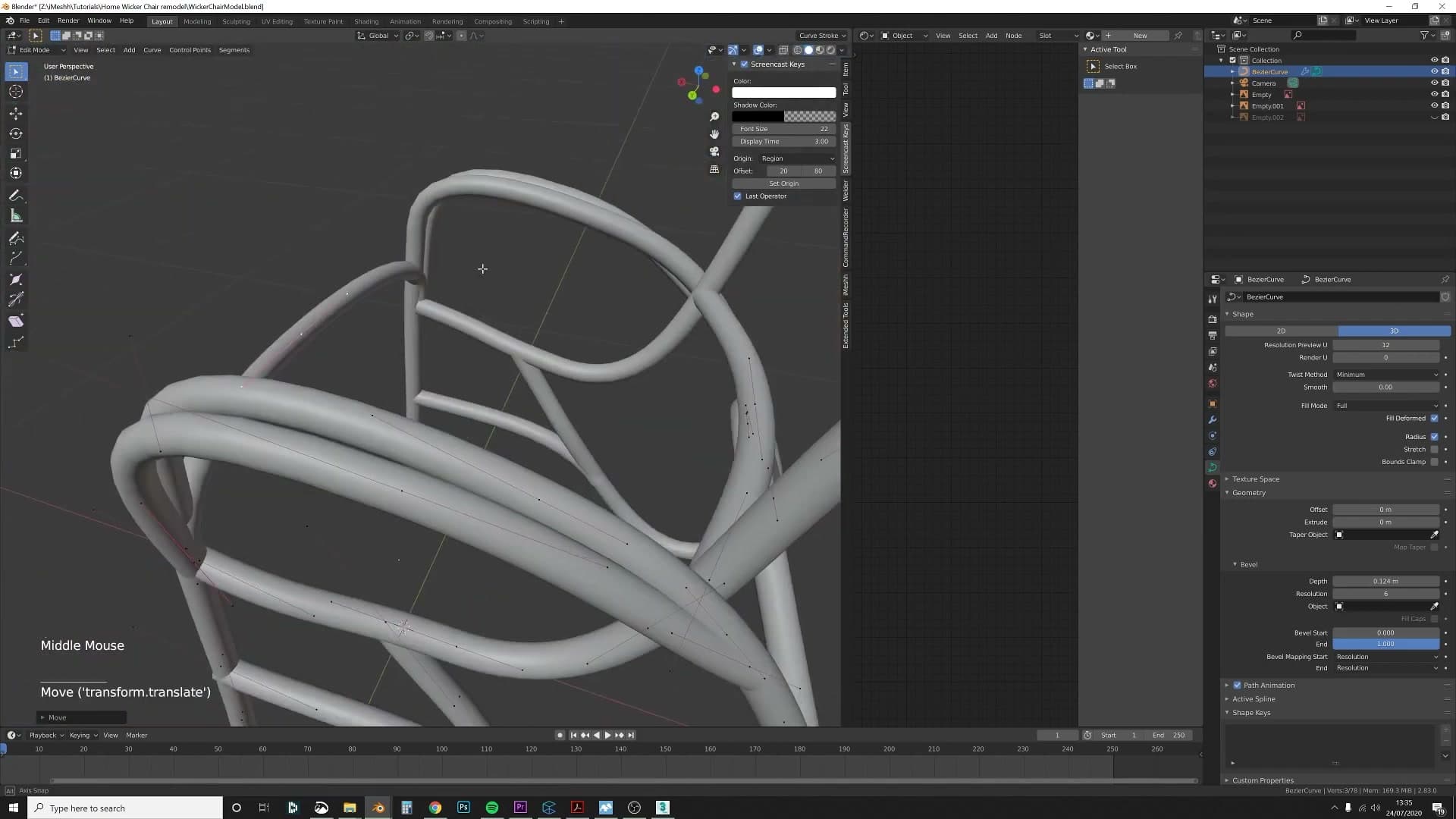
Once both halves of the rear frame are traced and mirrored, drop back to the main viewport and check the chair from all four orthographic angles before moving on. Anything that reads wrong from one angle - a curve that's too tall, a point sitting out of plane - is easier to fix now than after you start layering on the cover and bracing.
Building the woven seat wires
For the seat's woven wires, Kris simply duplicates the outer ring curve - which is already the correct shape - and extrudes the last point inward to fan out a series of seat-spanning wires. Proportional editing (O on the keyboard) keeps the organic curves flowing in the same direction, and the Mirror modifier handles the symmetry.
Duplicating the outer ring to scaffold the seat
With the frame in place, the next job is the woven wires that fan across the seat. The clever shortcut here: the outer ring you already traced is exactly the shape the seat needs to follow at its edge, so you don't need to start a new curve from scratch. Just duplicate the one you've got.
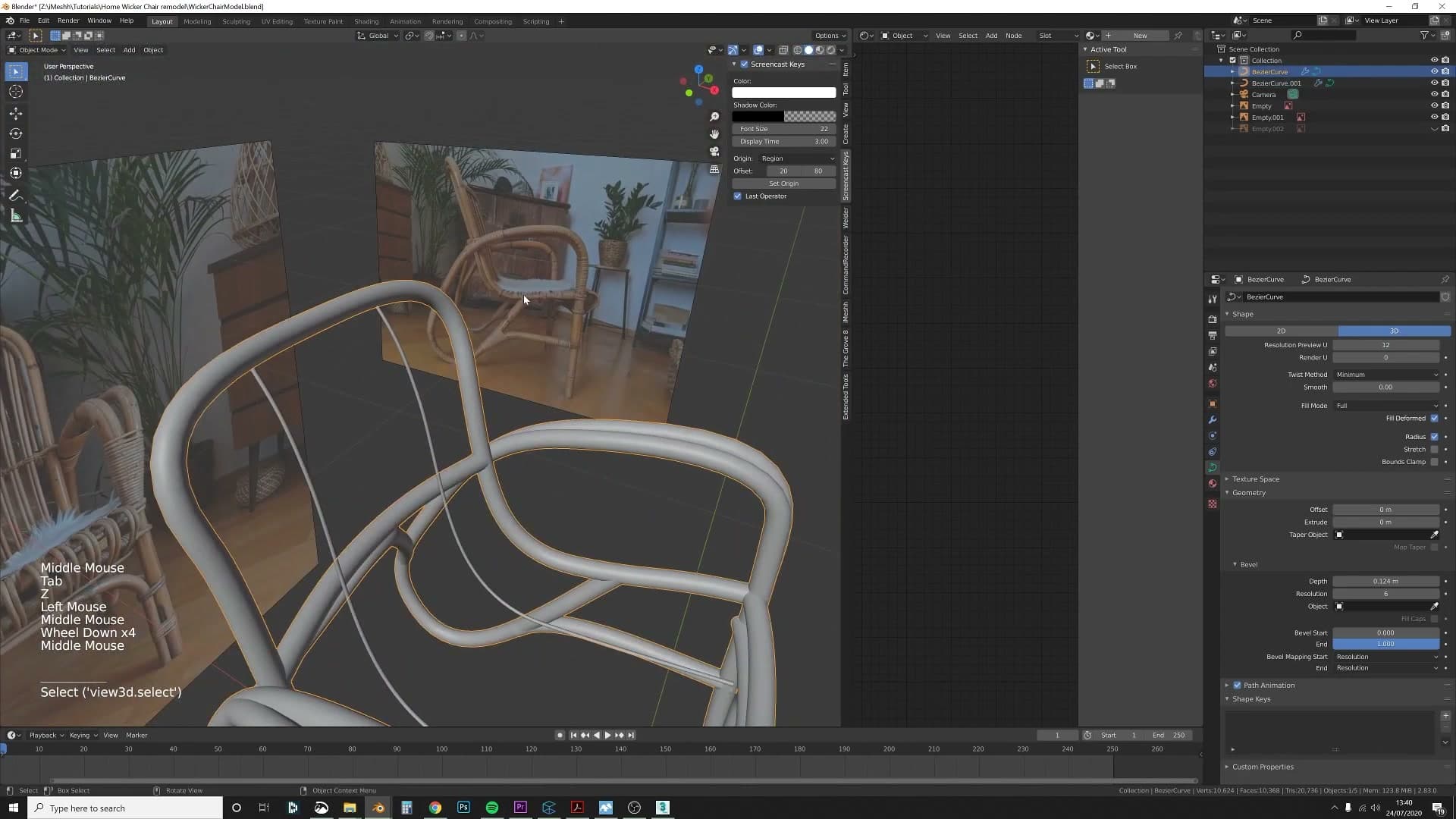
Select the outer frame curve and duplicate it with Shift+D. That single action gives you the correct outline for the seat opening. From there, drop into edit mode, grab the end point of the duplicated curve, and extrude it inward across the seat so the wire spans the gap. Nudge the new point into roughly the right position. It doesn't need to be perfect yet.
Because the chair has a Mirror modifier from module 2 onwards, you only need to build half of the seat wires. Everything you make on one side is mirrored automatically to the other, so a handful of curves becomes a full woven pattern.
Proportional editing for organic flow
Real woven seats don't have rigid, straight wires. They have organic curves that flow in the same general direction. To get that look without painstakingly placing every control point, turn on proportional editing.
Press O to toggle proportional editing on. Now when you grab a single curve point and move it, the points around it are pulled along with a soft falloff. Scroll the mouse wheel mid-move to grow or shrink the falloff radius. A wider radius drags more of the curve; a tighter one keeps the motion local.
This is the tool that gives the seat its flowing quality. Rather than each wire being shaped independently, neighbouring points follow each other naturally, so the whole weave reads as one continuous organic surface.
Duplicating across to fill the seat pattern
Once the first wire is shaped to your liking, the rest of the seat is built by repeating the same trick. Duplicate that wire with Shift+D, shift it across to the next position, and adjust the end points so it lands cleanly on the curved frame.
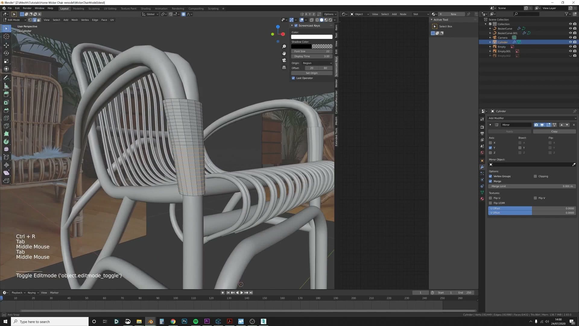
Work your way across the seat one wire at a time. As you get closer to the corners, the frame curves more aggressively, so the end points of each new wire need a little extra tweaking to sit flush. This is where things get fiddly. Use proportional editing whenever you want a wire's whole length to shift in sympathy with its end point.
This is where Bezier curves really earn their place over mesh modelling. Because every wire is still a curve, you can grab control points and reshape any wire at any time without rebuilding it. No edge loops to manage, no topology to clean up. Move the points, the geometry follows.
When the visible half of the seat is filled, the Mirror modifier completes the woven pattern on the other side. What looks like a complex weave of dozens of wires is really one duplicated curve, repeated and tweaked across the seat.
Wrapping cylinders around the frame and splitting cores
Next, Kris adds a cylinder that wraps around the entire frame to represent the chair's outer cover layer. Where the back meets the arms, the cover splits into two sections - he handles this by adding loop cuts, separating the cylinder into two objects, and proportional-editing them apart. The front legs get a special treatment: two thicker wires pass through the cover, deforming the cylinder loops outward to suggest tension.
Adding a cylinder around the frame
Kris admits up front that he forgot to hit record before starting this pass, so the walkthrough picks up after the fact. The technique itself is the same one you used on the frame: add a cylinder, then run it all the way around the shape so it wraps the entire chair as an outer covering layer.
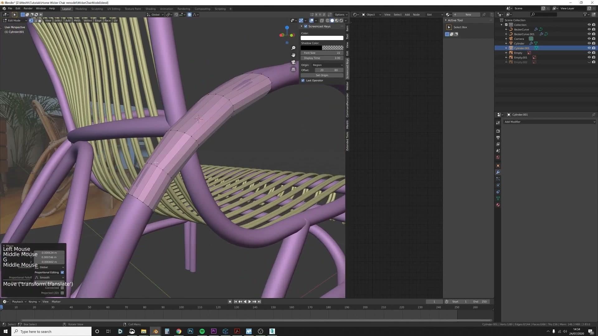
Treat this cylinder as the cover that sits over the structural frame underneath. Once it's tracing the full silhouette, you've got the base form to start cutting and deforming in the next steps.
Splitting cores at the arm-back junction
This pass is fiddlier than the front of the frame. On the real chair, the centre point where the back meets the arms isn't continuous. The covering visibly splits into two sections at that junction, and the model needs to suggest the same thing.
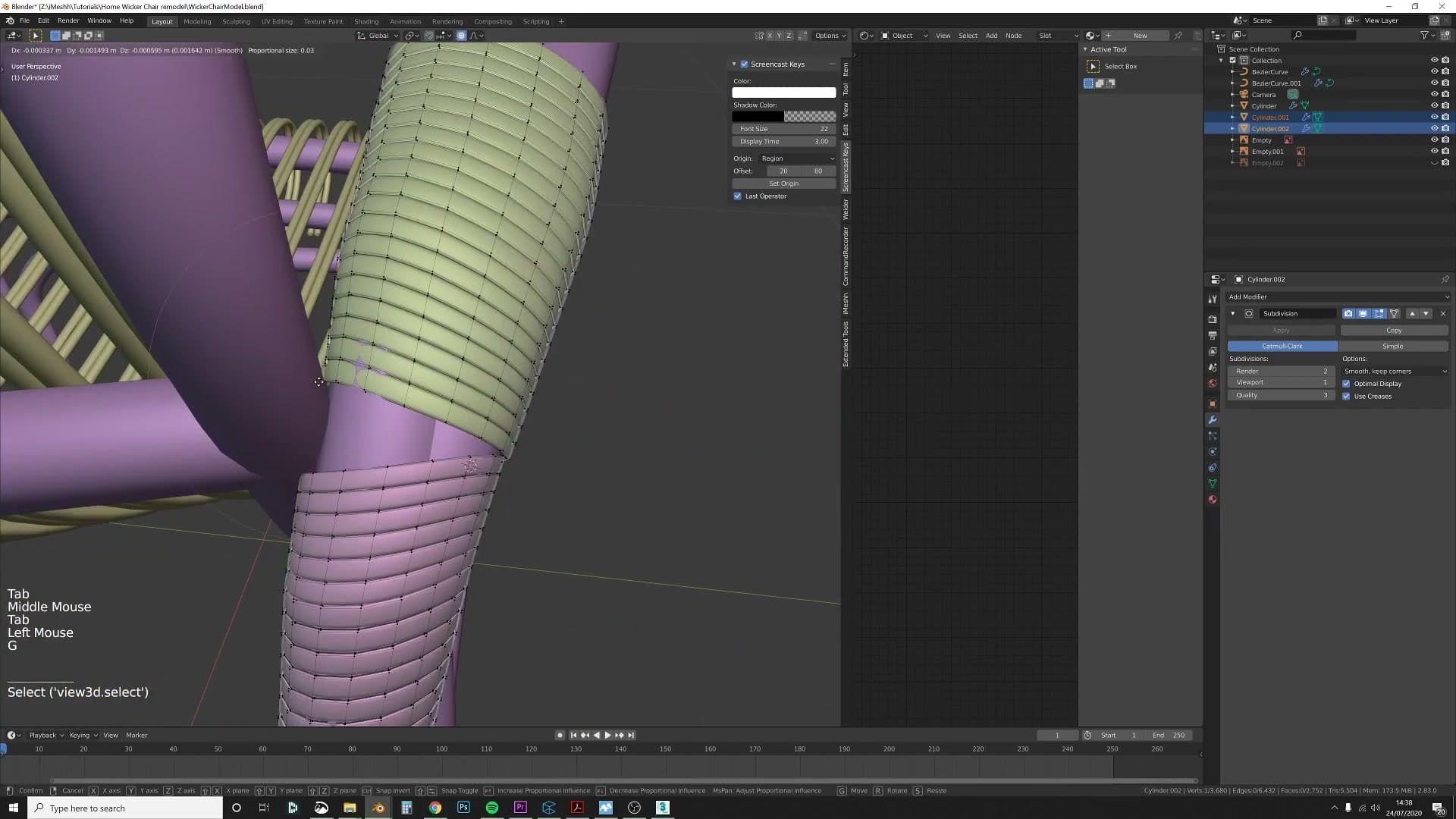
Work through it in three steps:
1. Add loop cuts that travel all the way around the cylinder, building up enough geometry across the join (the same density you used on the front). 2. Separate the cylinder into two objects at the split point. 3. Turn on proportional editing and gently pull the two halves away from each other so they part down the centre.
The result is a soft visual break where the back and arm covers meet, instead of one continuous tube glossing over a real structural junction.
Front legs as two thicker wires
The front leg section is structurally different from the rest of the chair. Instead of one continuous wrap, the front is only two parts wide: two thicker wires run down the front of the leg, and the cover sits around them. Kris admits on camera he doesn't know the correct furniture term, and lands on calling them wires; the blog follows suit.
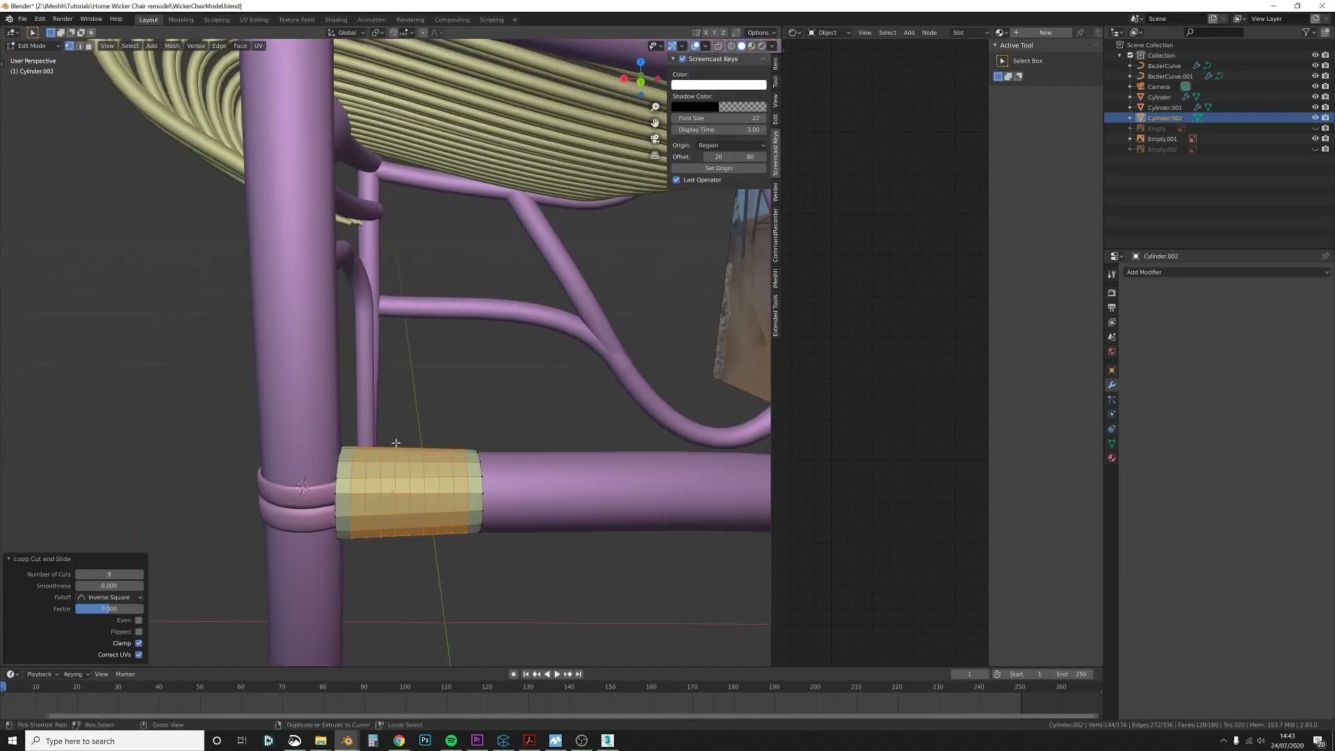
Build it in two stages. First, add another cylinder around the front section the same way you did for the back. Then extrude the two front pieces so they pass through that cylinder and continue down the leg.
You now have two thicker wires threading through the covering, with the cover itself wrapping the bulk of the leg. The geometry reads as a sleeve pierced by two structural members, rather than a featureless tube.
Deforming loops to show wire tension
The detail that sells this section is faking the tension those two wires put on the cover. In reality, a fabric or leather sleeve wrapped around two protruding wires wouldn't sit perfectly round. It would bulge outwards a little where each wire pushes through, pulled into shape by what's underneath.
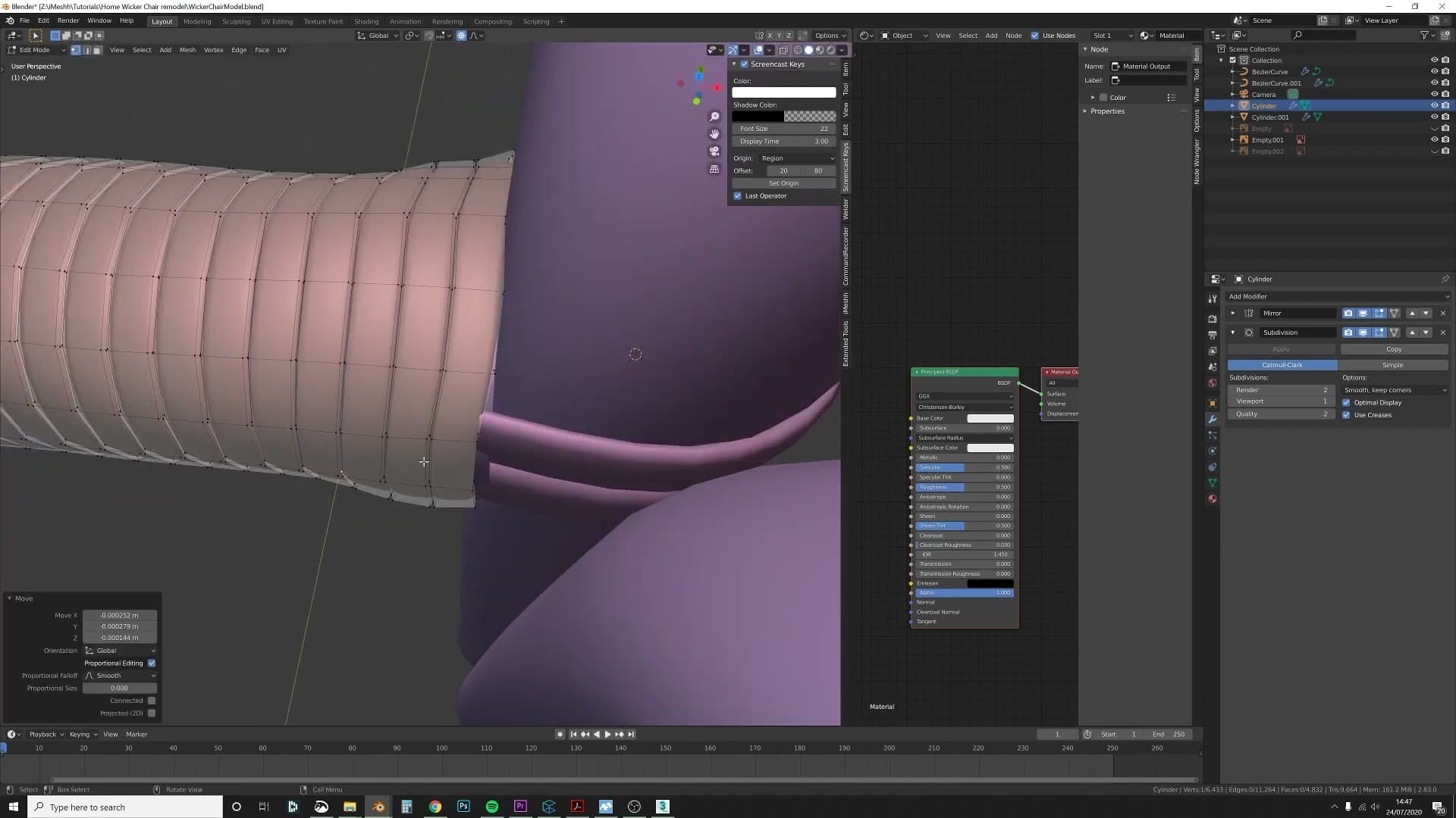
Edit the cylinder loops at the points where each wire passes through and nudge them outwards in the direction of the wire. You're not trying to recreate the physics exactly. Just enough distortion to read as a reaction to the structure beneath.
The cover now looks like it's actually being affected by the parts it's wrapped around, which is what makes the front of the chair feel like a real built object rather than a stack of separate primitives.
Cross-bracing with snap-to-face extrusion
Kris attempts the back cross-bracing by duplicating the front section but discovers it's a nightmare to refit - he should have restarted from scratch. The fix is to add a plane, turn on Snap > Face with vertex snapping, then extrude edges that stick exactly to the existing curved surface. Clicking each vertex individually onto the target geometry turns out to be faster and more accurate than freehand placement.
First attempt and the decision to restart
Kris's first approach to the back cross-bracing was to duplicate the section he had already built lower down on the chair and try to refit it to the new curve. It did not work. The geometry stretched and twisted around a different radius, and forcing it to sit cleanly became, in his words, an absolute nightmare.
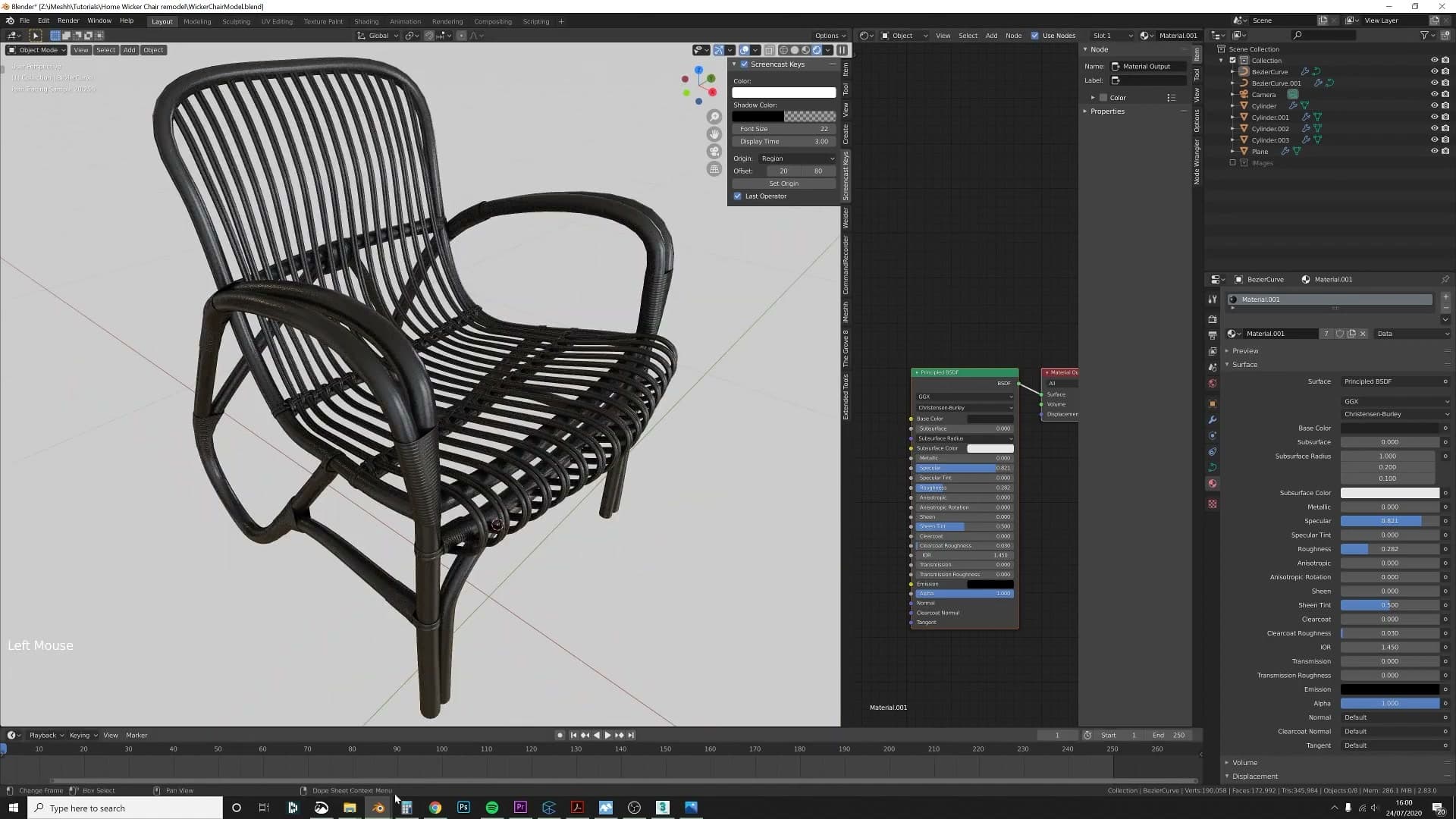
With hindsight he should have cut his losses sooner and started fresh from the beginning rather than wrestling with the duplicate. He admits this on camera. The lesson is more about pattern recognition than technique. When an approach is fighting you for several minutes and the gap to a clean result keeps widening, restart.
Before scrapping the attempt he also applied a temporary black, slightly shiny material to the frame so the highlights would catch every edge. That gave him a quick visual read on whether the existing curves were sitting right before committing any more work on top of them.
Snap-to-face vertex snapping
For the second attempt Kris reused the same starting idea as the bottom cross-bracing: drop in a plane to give yourself something to extrude from. The difference this time is the snapping setup.
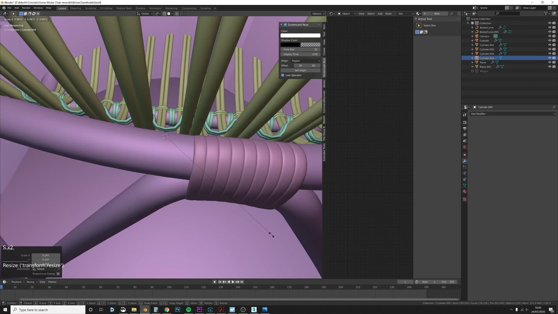
Add a plane near the area you want to brace, enable snapping in the header, and set the snap mode to Face. With snap-to-face active, every edge you extrude sticks to whatever surface sits underneath it, so the new geometry follows the existing curved frame instead of you trying to guess depth in 3D space.
This first pass still was not quite right. Kris does not go into the specifics of what was wrong with the initial snap configuration, only that he restarted and refined the workflow further on the next attempt.
Clicking each vertex individually for precision
The fix on the second attempt was to stop trying to snap entire extruded faces in one go and instead click each new vertex into place individually. That way every point you place lands directly on the target surface, and you can see immediately whether it is sitting where you want it.
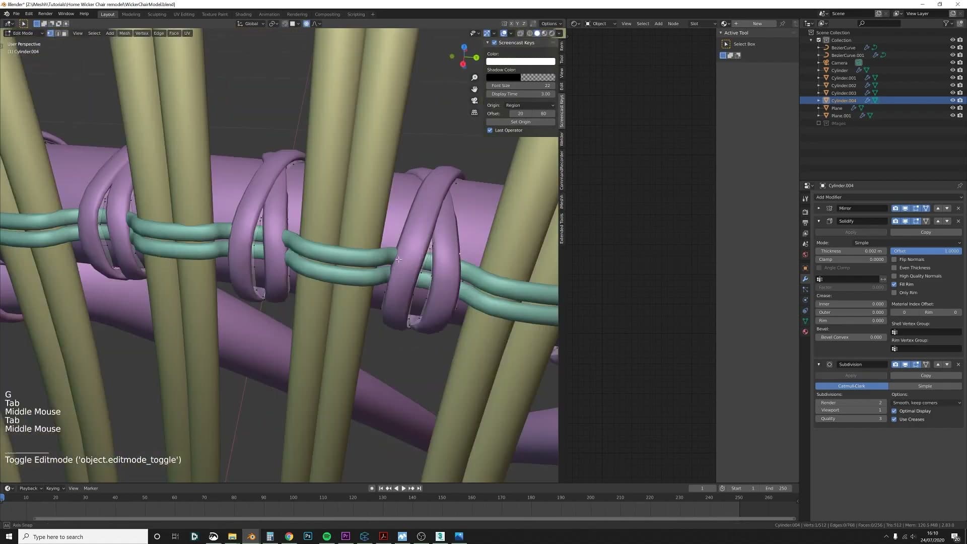
Kris found this slower-sounding workflow was actually quicker and far more accurate than freehand placement. Fewer corrections later, and the edges read as if they were always part of the curved frame.
The back cross-bracing is not a mirror of the bottom either. On the real chair the loops that pull this section inwards overlap in a cross shape rather than a square. Kris deliberately deviated from the photo reference here: in the real piece the cross-bracing does not continue around the back, but he routed his version all the way around and attached it to the centre back pole. Hiding that detail felt like a waste, and the wrap-around reads as more aesthetic for the rear of the chair.
The two intersecting cylinders at the junction were made by adding one cylinder, duplicating it, then rotating the duplicate into place. They are not perfectly aligned, and I'm happy to leave them that way. The chair is an organic shape, and the small imperfections add to the realism rather than working against it.
Half-circle bevel profiles for wooden retaining strips
The wooden strips that pinch the back and sides of the chair are half-circles flat on one side. Kris creates a custom bevel profile by drawing a half-circle curve and assigning it as the bevel object of a duplicated frame curve. Ctrl+T tilts each control point so the flat side faces the right direction, and the same trick is used for the bottom retainer.
Creating the half-circle bevel profile
The strips you've just laid into the seat aren't held in place on their own. A separate wooden retainer pinches them against the frame. The cross-section is half-round: convex on the outside, flat on the inside, so the flat face presses cleanly against the strips it's clamping.
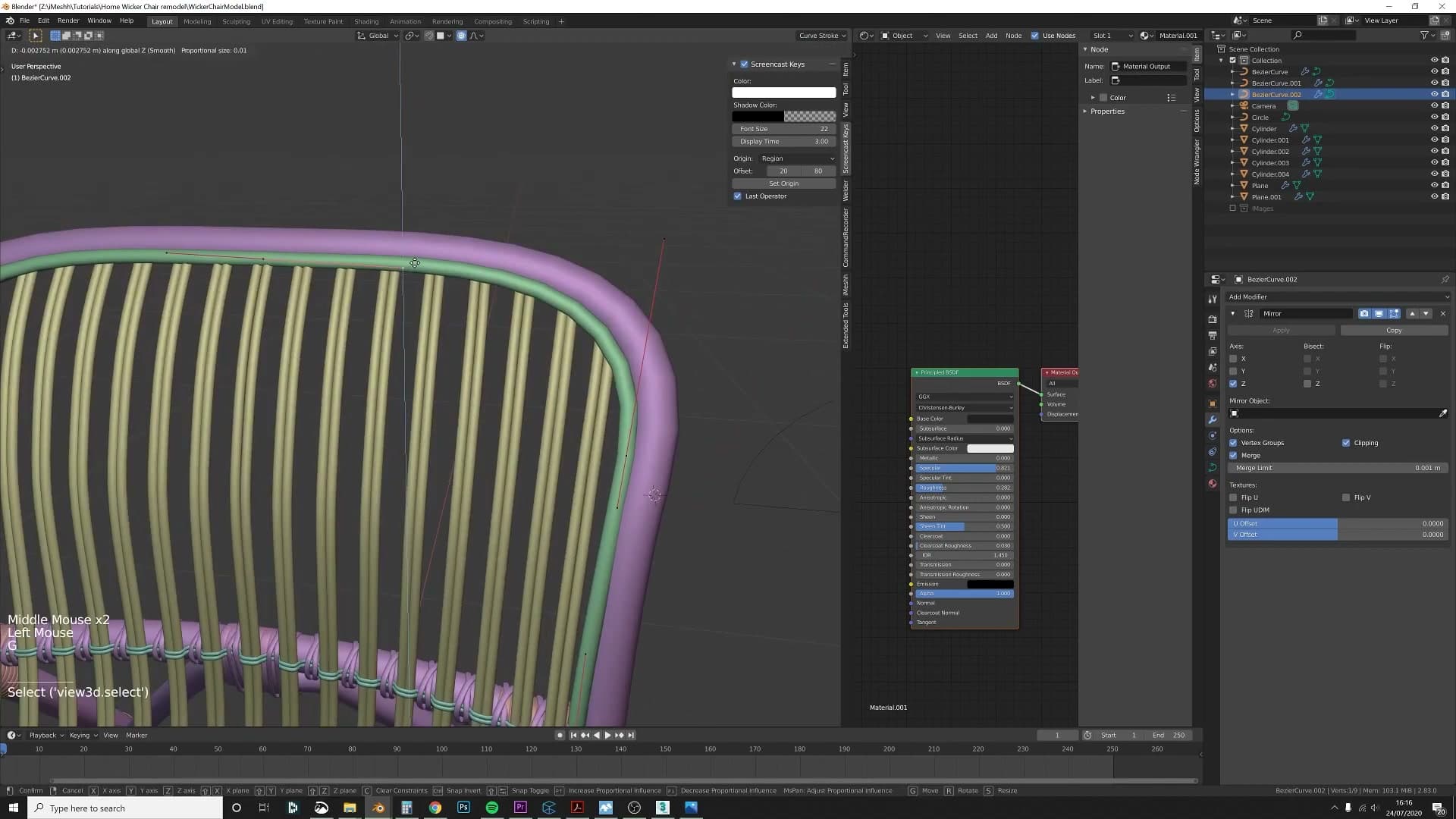
To build it, duplicate the outer frame curve you've already drawn so the retainer follows exactly the same path round the chair. Then, separately, draw a small bezier curve in the shape of a half-circle - this is the custom bevel profile you'll use to give the retainer its flat-backed look.
With the duplicated frame curve selected, open the Object Data Properties and assign the half-circle curve as its Bevel Object. The curve immediately extrudes along its length as a flat-backed half-round strip, ready to be slid into position against the seat.
Tilting curve points with Ctrl+T
A half-circle profile only reads correctly when the flat face is pointing at the strips it's meant to clamp - and as the retainer curve bends around the chair, that orientation will drift. By default each control point holds the bevel profile at whatever angle Blender chose for it, which often means the flat side rolls outward in places where you need it pointing in.
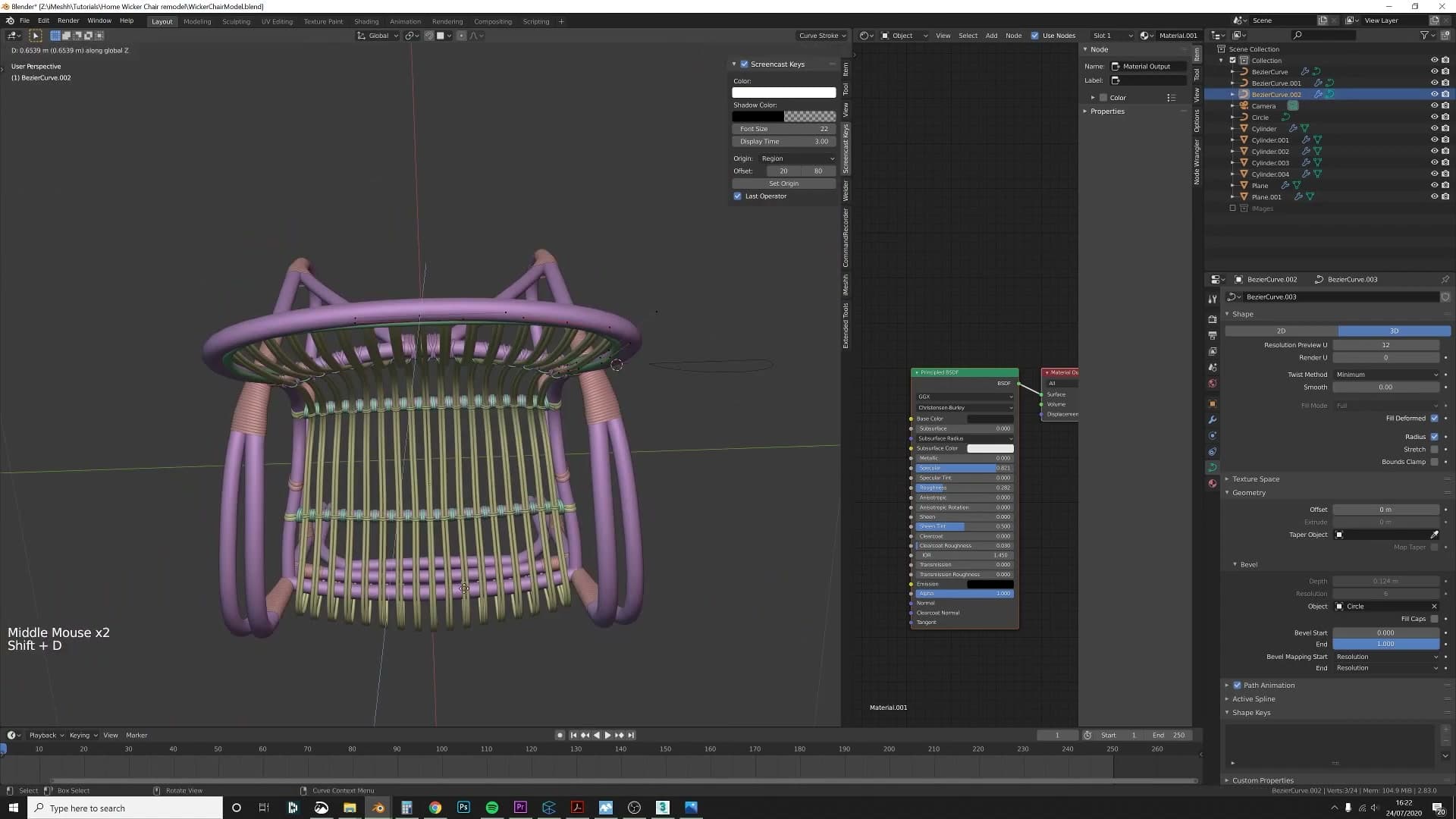
To correct it, drop into Edit Mode on the duplicated curve and select one control point at a time. Press Ctrl+T and move the mouse to rotate the cross-section around the curve, then click to confirm once the flat face is pointing inward. Work along the curve point by point until the flat side consistently presses against the strips it's holding.
Duplicating the retainer to the back of the chair
With one retainer pinning the strips in place at the front, duplicate the whole strip and move the copy round to the back of the chair so the same flat-faced wooden piece clamps the rear strips against the frame.
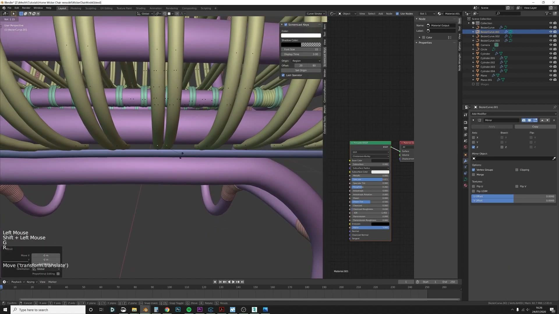
The same half-circle profile is reused along the bottom of the chair, where it holds the lower set of strips in. Duplicate the retainer again, route it along the underside, and tilt the control points so the flat side faces the strips it's meant to grip. On a real chair these wooden pieces are pinned in place with small nails, but those join points are hidden from any angle you'd realistically render, so they can be left off the model entirely.
UV unwrapping with seams on hidden edges
Once everything is converted from curves to mesh, Kris marks seams along the hidden underside edge loops, selects all and presses U to unwrap. Because the converted curves have no end faces, the unwrap is clean. He rotates UVs to align wood grain consistently and uses the UV Squares plugin to straighten wonky rectangles. Lesson learned: mark a seam on the original curve before converting, so every subsequent ring inherits it.
Applying modifiers and converting curves to mesh
At this stage the chair is structurally finished. Every curve is in place, the bevels look right, and Kris is happy enough with the silhouette to start thinking about render composition. Before doing anything irreversible, you want a safety net.
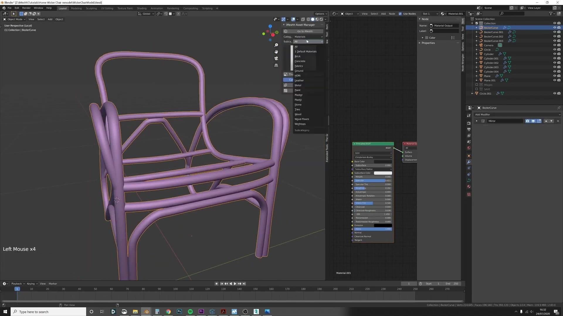
First, drop a floor plane underneath the chair. It costs nothing and gives you a sense of how the proportions read against a ground surface, which is useful when you start lighting later. Then duplicate the entire chair, move the copy into its own collection, and hide that collection out of the way. The duplicate is your insurance policy.
On the working copy, apply the modifiers and convert each Bezier curve into a mesh (Object → Convert → Mesh). You're doing this because the next stage (marking UV seams and assigning a wood material) needs editable mesh geometry, not live curves. The hidden duplicate means if anything goes wrong you can come back to the curve setup without rebuilding from scratch.
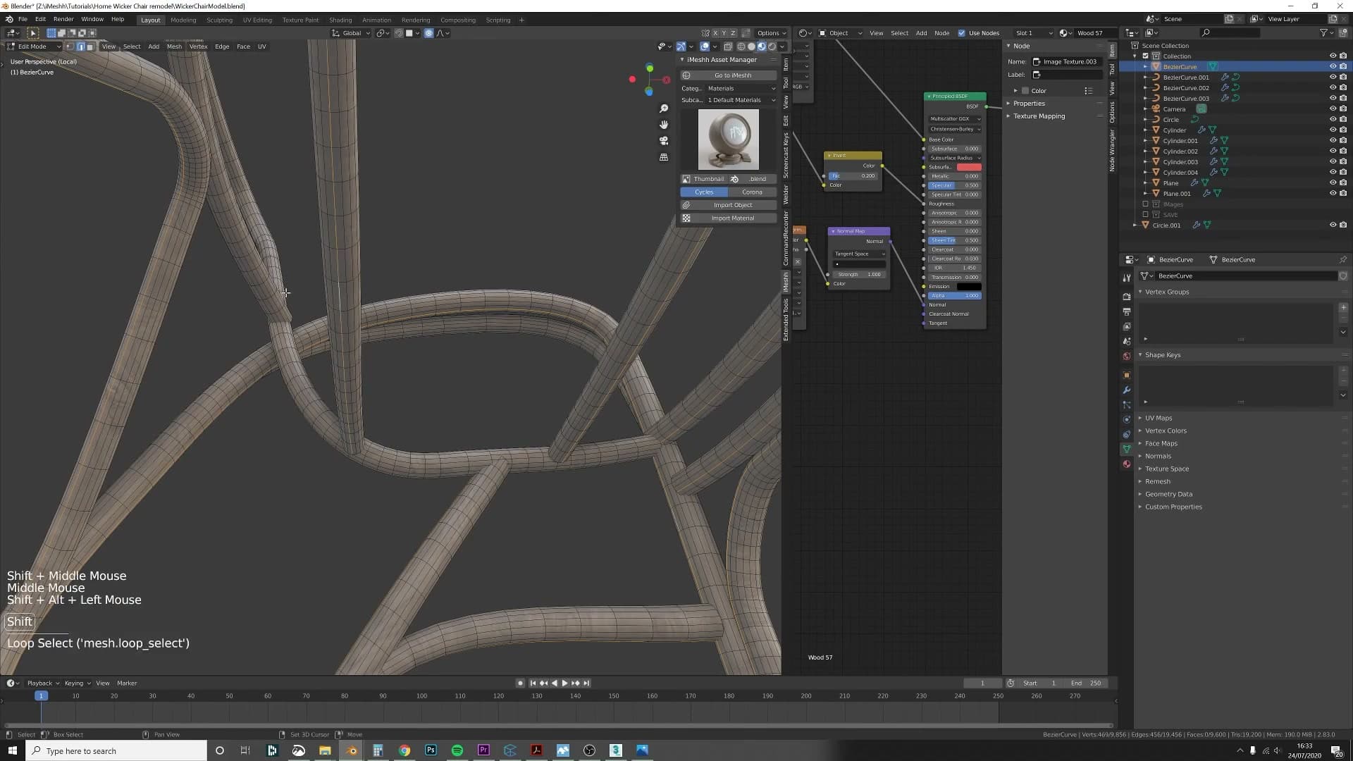
Rotating UVs for wood grain alignment
The chair is going to be textured with a real wood material, and real wood has grain that runs along the length of each part rather than across it. By default the unwrap won't know which way 'along' is, so a chunk of the islands will land rotated 90° relative to the rest. You need to walk through the UV editor and straighten them out.
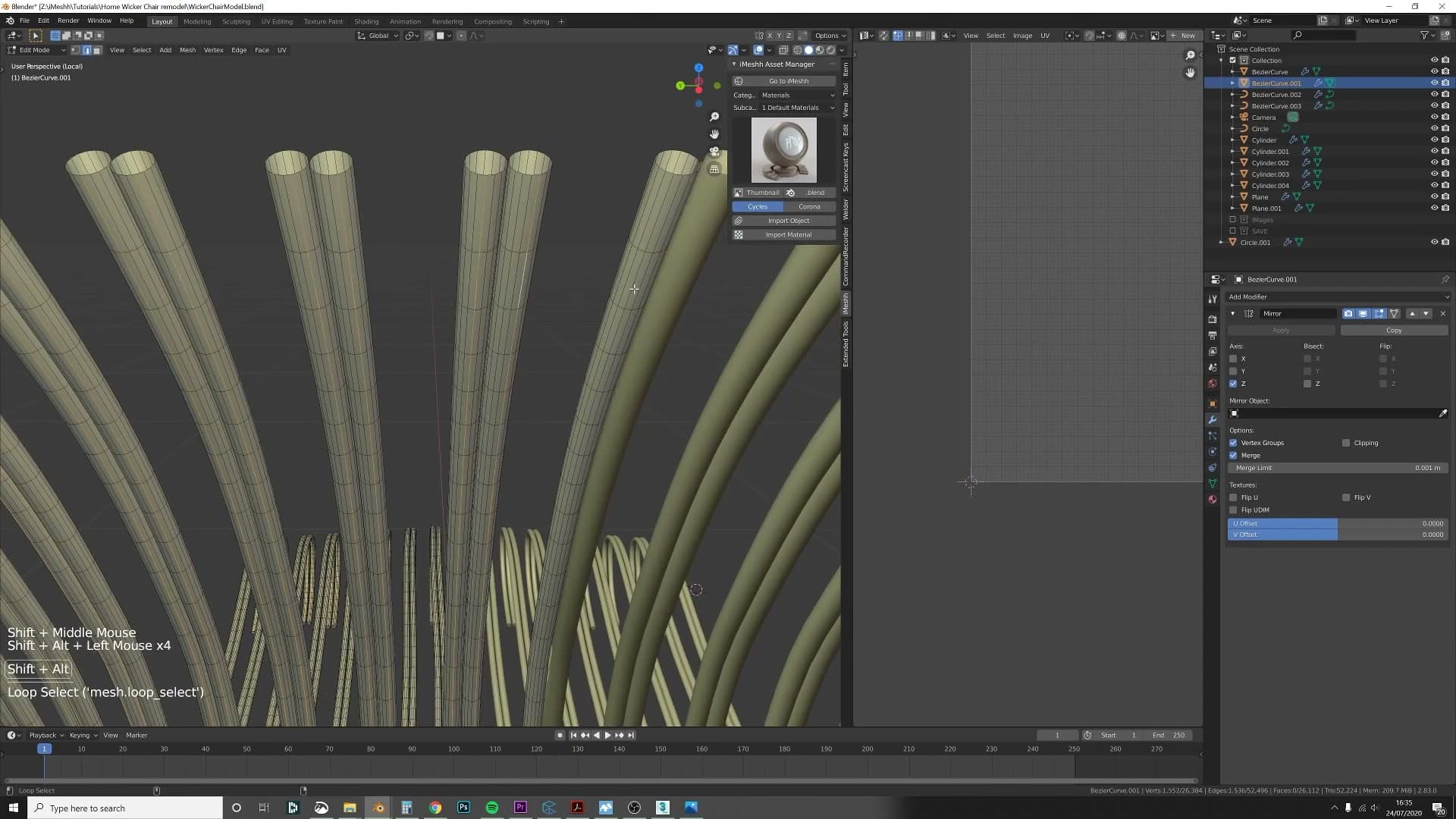
In the UV editor, hover over an island that's running the wrong way and press Ctrl+L to Select Linked. That grabs the whole island in one click. Then press R, type 90 and hit Enter to rotate it. Move to the next misaligned island and repeat. Ctrl+L, R, 90: find the rhythm and it goes quickly.
Don't worry about catching every island on the first sweep. If you spot a stray one still running the wrong way after you think you're finished, just rotate that one on its own. Kris missed one on the first pass and circled back to fix it without redoing anything else.
The same routine applies to the back sections. Select everything, unwrap, then walk the UV editor rotating any islands that don't sit with their length along the U axis until the grain reads consistently across the whole chair.
Straightening wonky unwraps with UV Squares
At this point I hit the wires. These are the thin sections that wrap many, many times around each part of the frame. Because they were arrayed without a UV seam marked on the source curve, every single instance now needs its seam added by hand. Edge loop by edge loop, around every wrap, marking seam. It only takes a few seconds per piece, but the count adds up.
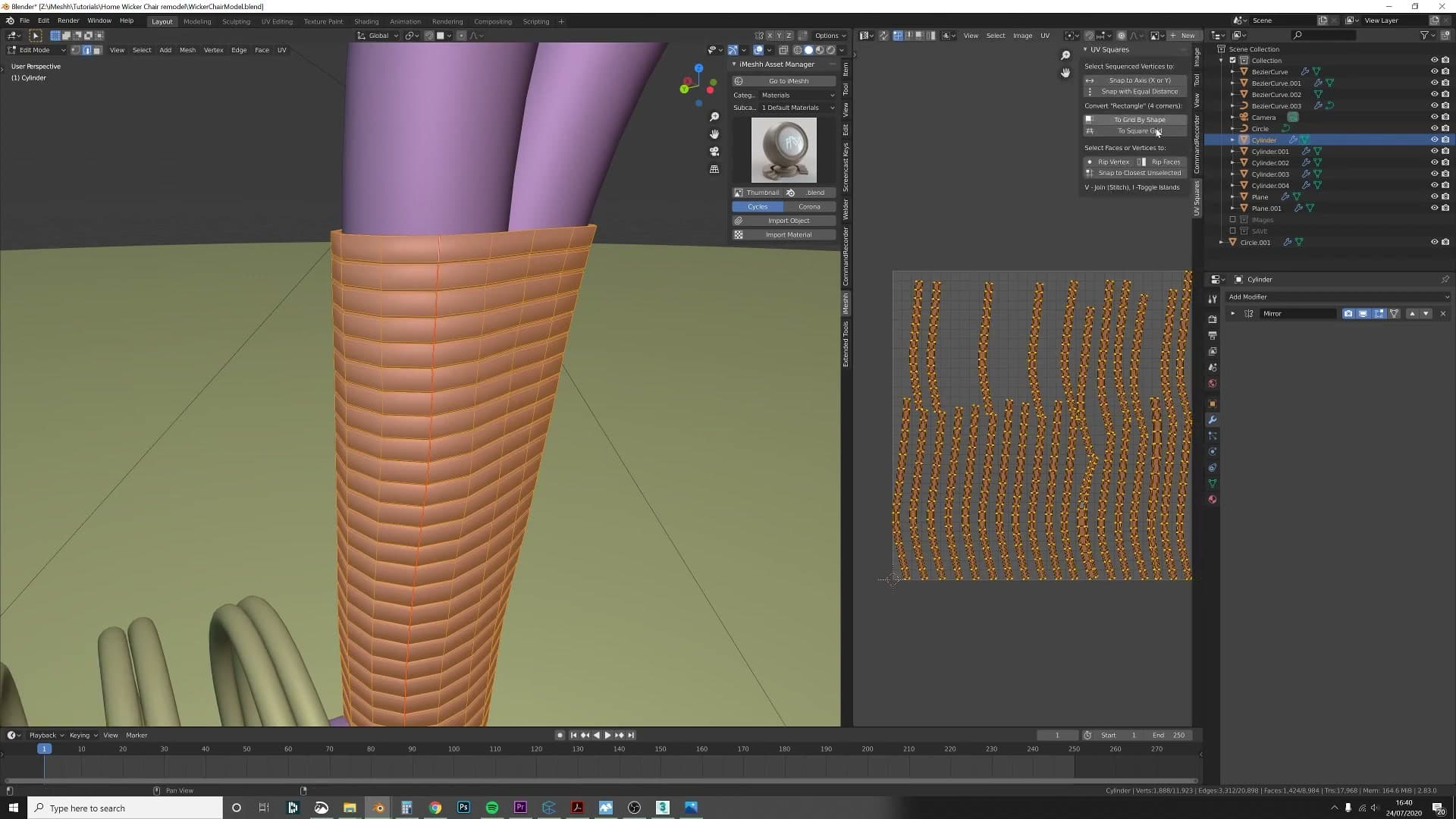
Even with the seams marked correctly, the unwrap on a long, gently twisting tube doesn't always come out as a clean rectangle. It lands as a wonky parallelogram, which makes a tileable wood texture skew across the surface. This is where the UV Squares add-on earns its keep.
Install UV Squares (search 'UV Squares Blender 2.8', it's a free community plugin). In the UV editor, select the wonky island, then click the UV Squares button in the side panel. The parallelogram snaps into a clean rectangle.
For tileable wood textures that's exactly what you want: perfectly rectangular UVs mean the grain runs straight along the part with no skew. Walk round every section: unwrap, square, move on. Tedious for a moment, then done.
Adding end caps and validating chair scale
Many of the curves still have open ends after conversion to mesh. Kris uses Shift+G with 'edges by amount of faces' to select all open edge loops at once, fills them with F, and adds a tiny bevel with Ctrl+B. He then drops a 0.45m cube next to the chair as a height sanity check - the chair is the right size.
Shift+G to select open ends and fill
After converting all the curves to mesh you'll spot a snag: every tube is still hollow at the ends. The bevel only wraps the sides of the curve, so wherever a piece terminates you're left with an open boundary loop that needs capping.
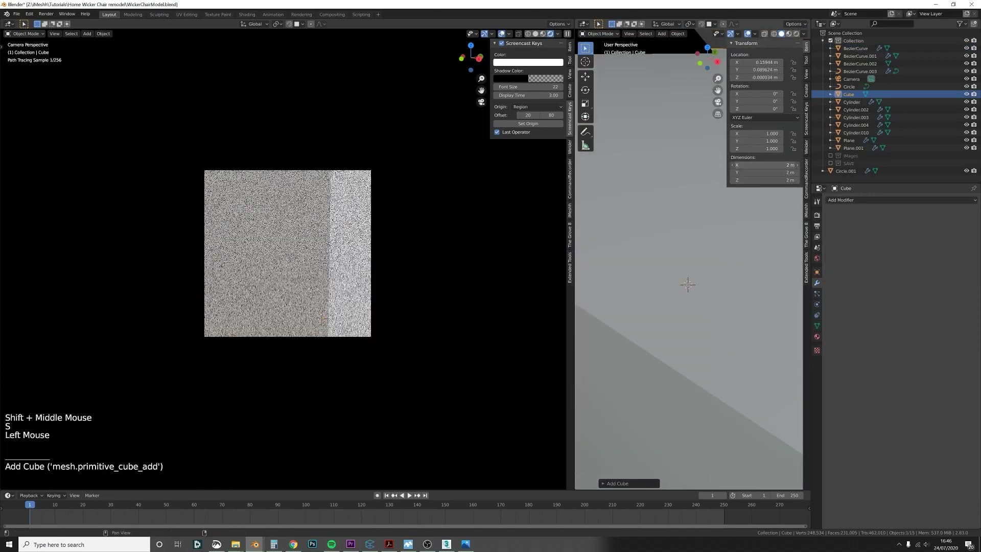
Rather than hunt every open end down individually, let Select Similar do the work. Switch to edge select mode, click a single edge that sits on one of the open ends, then press Shift+G and choose the option for edges with a similar amount of faces around them. Because an open boundary edge has only one face attached, that one click selects every open loop on the chair in one pass.
With everything highlighted, press F to fill the loops in, then Ctrl+B and drag in a small amount for a subtle bevel. The slight chamfer stops the new end caps reading as razor-flat discs once light hits them.
0.45m cube as a scale sanity check
Before moving on to materials, it's worth confirming the chair is roughly the size of a real chair. Reference photos in perspective can easily flatter or shrink a build without you noticing, and it's much easier to rescale now than after you've started UV unwrapping and texturing.
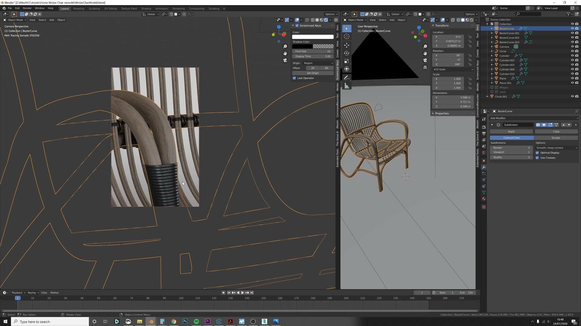
Add a default cube next to the chair and set its height to 0.45 m, a general seat-height figure for a standard chair. Park it alongside the seat and eyeball the match. If the top of the cube lands somewhere near the seat surface, the chair is in a believable range and you can carry on; if it's wildly off, scale the whole chair up or down before the next step.
Studio scene with shadow catcher and three-light setup
To preview materials in a controlled environment, Kris turns the floor plane into a shadow catcher and adds three area lights: a big soft fill, a focused key from the side, and a back/rim light to define the silhouette of the arm. He demonstrates each light in isolation so it's clear which parts of the chair each one shapes - a useful workflow when iterating on materials.
Floor as shadow catcher
Before settling on the final materials, you want to preview the chair in something closer to a real studio environment - otherwise it's hard to judge how the surfaces will read once they're lit properly. The fastest way to fake that studio look is to leave the floor plane in place but stop it from rendering as a solid object.
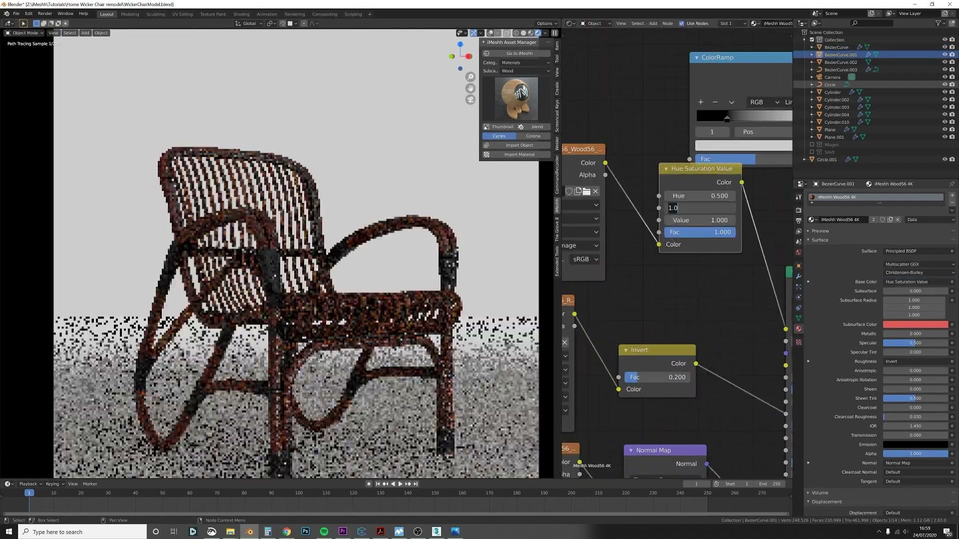
Select the floor and turn it into a shadow catcher in the object properties. The plane itself disappears from the render and only the shadows the chair casts onto it remain, so the chair appears to sit on a clean studio backdrop rather than a visible piece of geometry.
Three-area-light setup: fill, key, and back
With the floor catching shadows, the next problem is lighting. White studio lighting makes material choices much easier to judge, so you're aiming for a clean three-light rig built entirely from area lights.
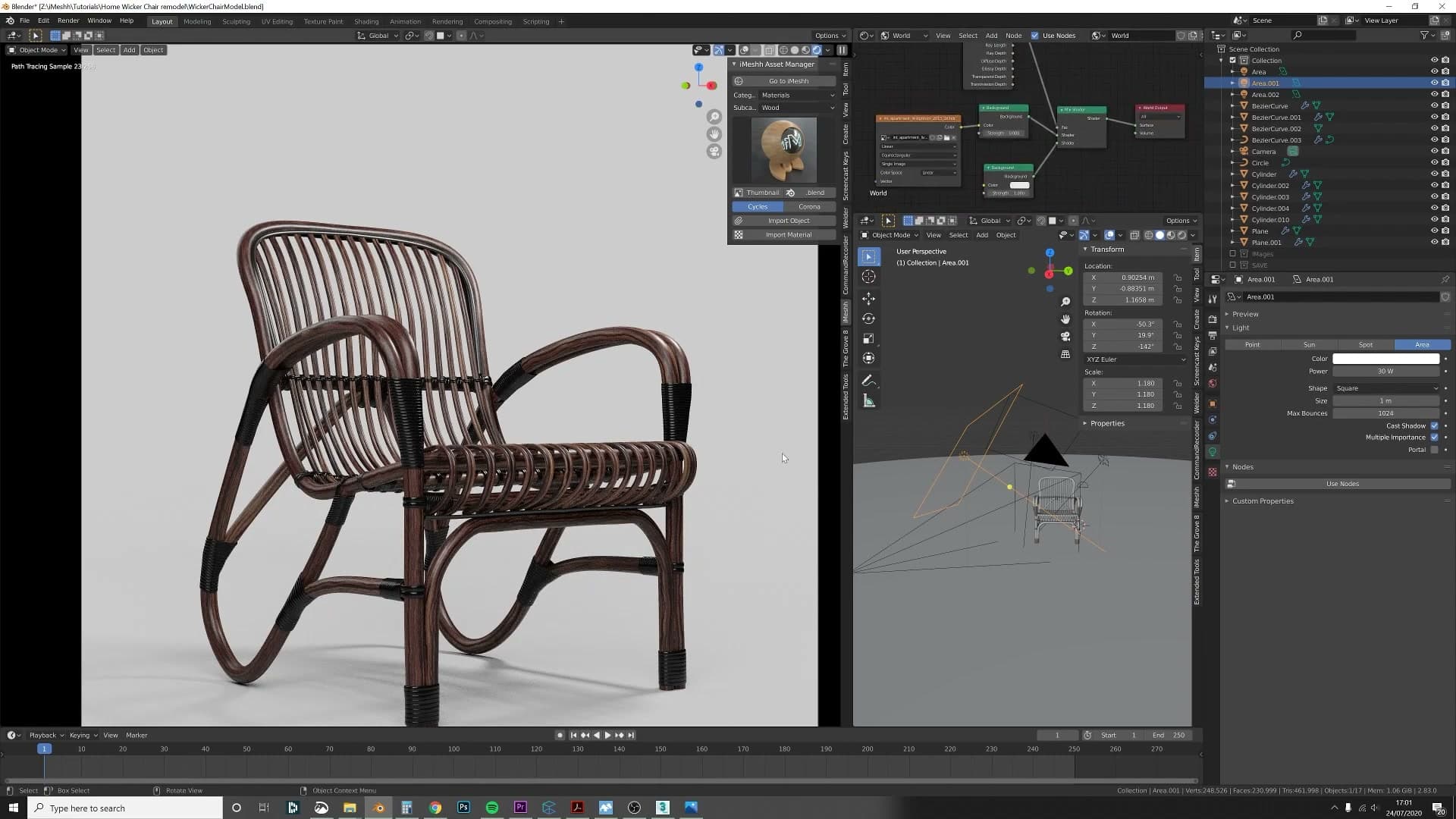
Add the lights one at a time. The first is a big fill light - a wide area light that gives the whole scene a soft, even base. The second is a key light placed to the side, smaller and more focused so it picks out form and adds contrast where the fill is too flat. The third is a back light aimed from behind the chair, which rims the silhouette - watch the top of the left arm and you'll see a bright highlight appear once it's switched on.
Before combining them, go around each light and toggle them on individually. Seeing which part of the chair each light is actually shaping is a very important step when you're trying to judge a render, because it tells you which light to push or pull when something isn't reading right.
Adding the missing leg-floor detail
Looking at the test render, you'll notice the chair isn't quite touching the floor - the bottom of each leg hovers a hair above the plane, which kills the sense that the object is actually grounded.
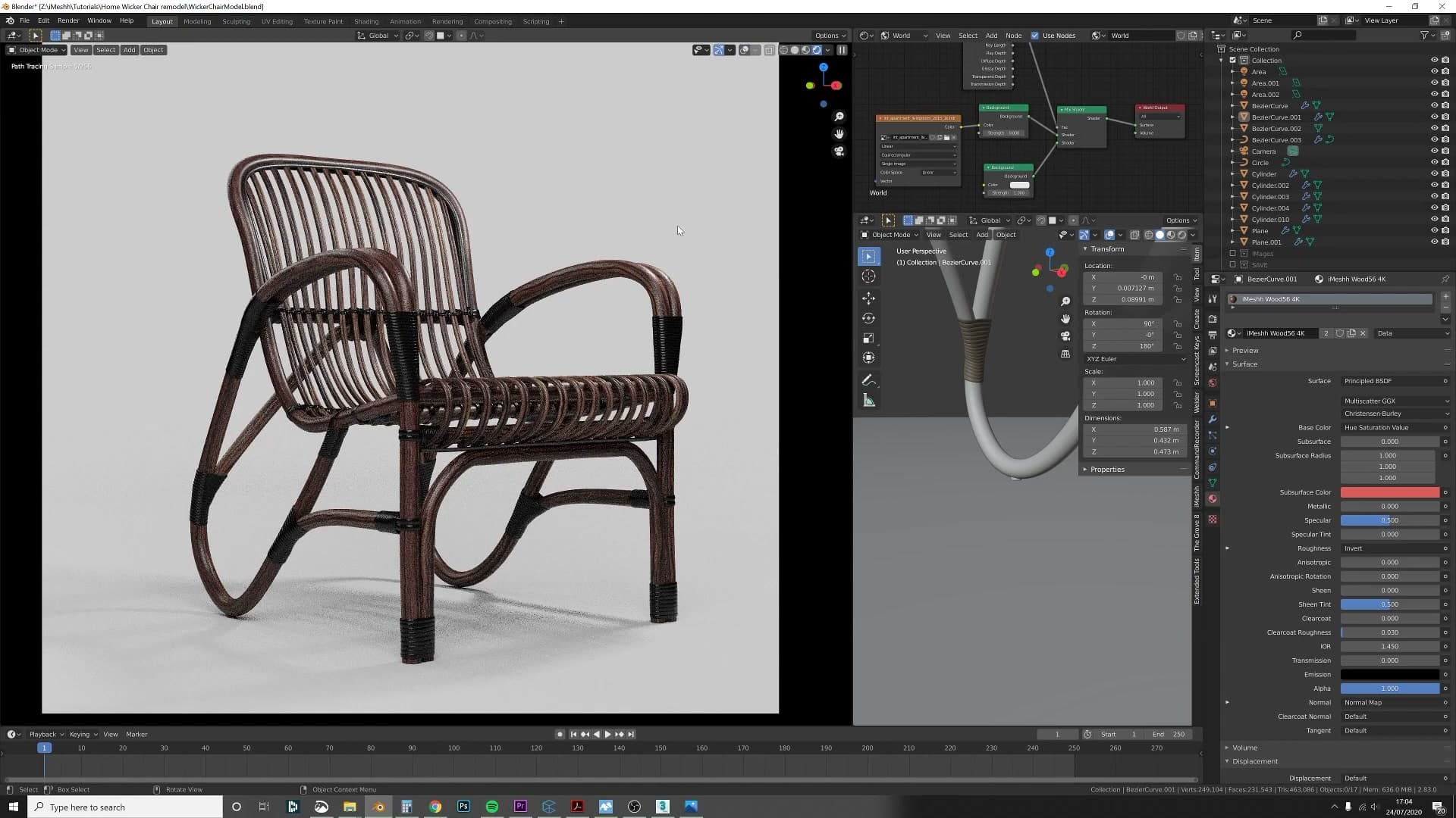
Model a small cap shape on the bottom of each leg so it makes contact with the floor. It's a tiny piece of geometry, but it adds a surprising amount of nice detail through the shadows it casts - a small dark contact patch where each leg meets the ground.
Never forget about these kinds of small things. The leg-floor cap is easy to skip while you're focused on the big curves, but it's exactly the sort of detail that lifts a render from "floating model" to "object sitting on a surface".
Decorative nails with array + curve modifier
The decorative nails that line the wooden retainer are built once as a flattened sphere with a metal material, then driven by an array modifier whose curve modifier follows a curve duplicated from the chair's edge loop. Ctrl+T tilts the curve points so every nail faces outward from the chair - a clean, non-destructive way to scatter geometry along an organic edge.
Duplicating an edge loop and converting to a curve
The decorative nails that line the wooden retainer don't need to be modelled individually. Instead, you can scatter one nail along the existing edge of the chair by borrowing the geometry that's already there. Drop into edit mode on the retainer, select an edge loop that runs neatly along the line where you want the nails to sit, and duplicate it.
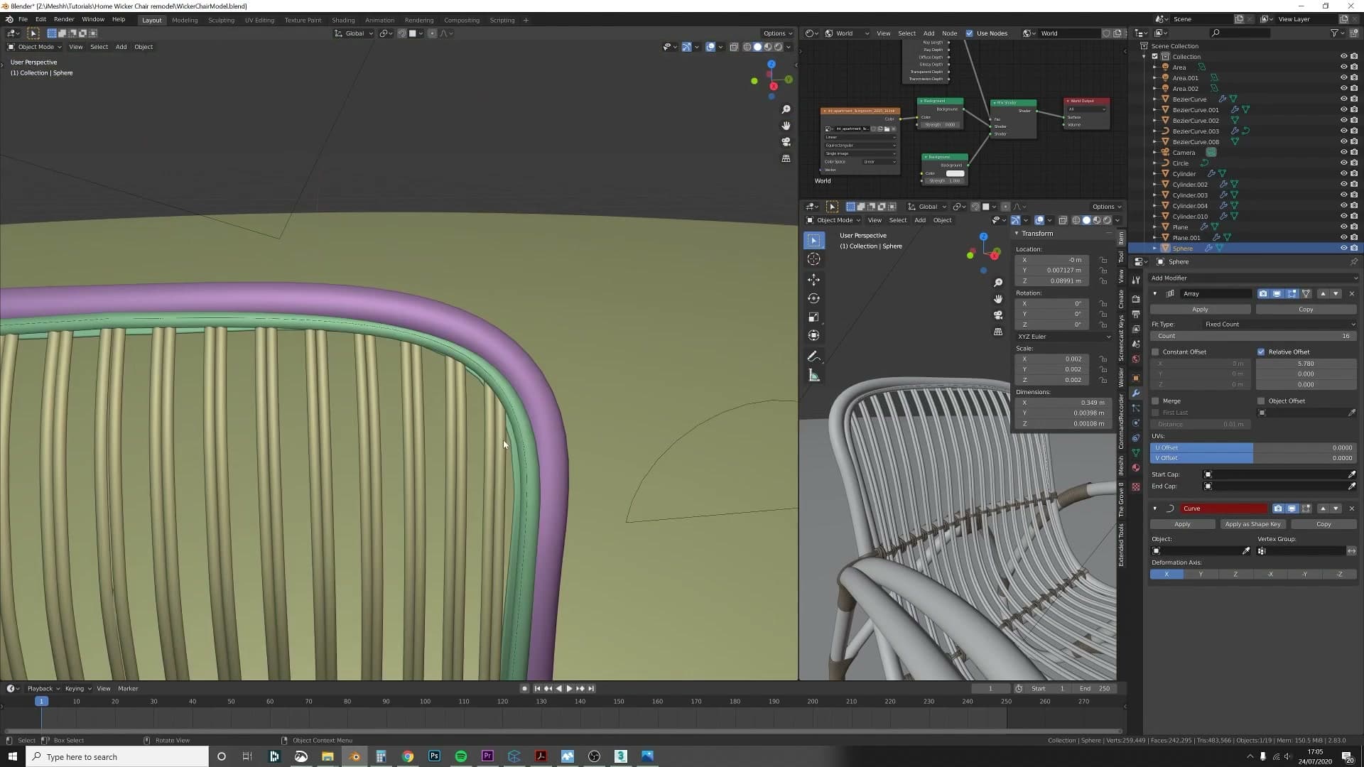
With the duplicate still selected, press P to separate it into its own object. Then jump back into object mode, select the new edge-loop object, and convert it from a mesh to a curve. That curve becomes the path that the array of nails will follow. No freehand drawing required, because the loop already traces the exact contour of the chair.
Array modifier driven by a curve modifier
Build the nail itself as a simple primitive: add a UV sphere and flatten it so it reads as a domed nail head rather than a full ball. Give it a clean metal material. I keep this deliberately understated so the nails feel like an accent, not the hero.
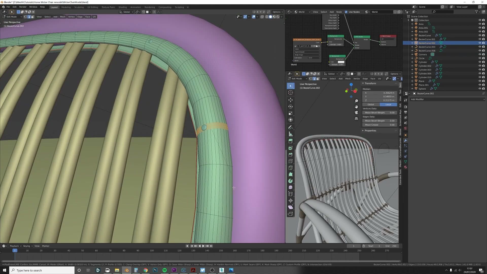
Now stack two modifiers on the nail. Add an Array modifier first to repeat the sphere along one axis, then add a Curve modifier underneath and point it at the curve you separated in the previous step. As soon as the curve is wired in, the entire array bends along the edge loop and wraps continuously around the chair.
Adjust the array count and offset until the spacing looks right and the nails meet up cleanly around the full loop. One sphere now becomes a complete decorative trim.
Ctrl+T to tilt curve points so nails face outward
When the array first snaps onto the curve, some of the nails will be facing the wrong way, twisted inwards or sideways instead of pointing out from the chair. The fix happens on the curve, not on the nails.
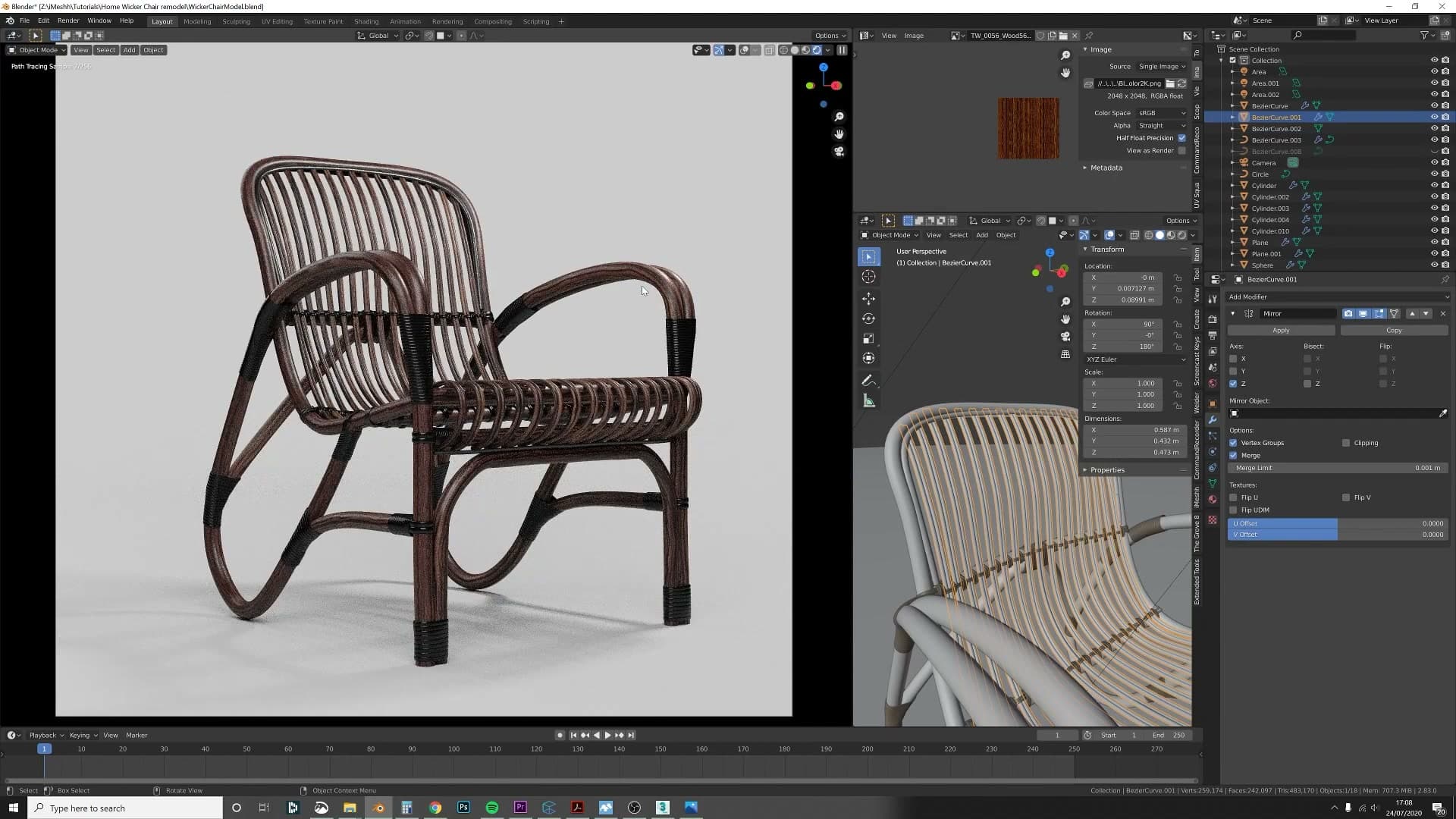
Select the curve, drop into edit mode, and pick the control points where the nails look wrong. Press Ctrl+T and move the mouse to tilt that point. As you tilt, every nail influenced by that point rotates around the curve's tangent, so misaligned heads swing into line with the rest. Confirm with a click, then work along the curve fixing any remaining points.
It's worth flagging what's actually happening here: you're rotating the curve's tilt, not the nail object. The nails inherit their orientation from the curve, so editing the curve is the only place this can be controlled cleanly.
Once every point is tilted correctly, the whole row of nails faces outward in a uniform line. A small detail, but it's what sells the retainer as a real piece of upholstered furniture rather than a row of floating spheres.
Camera composition and Photoshop normal map
For the final render, Kris angles the camera 90 degrees to the chair and enables depth of field. The wood texture's stock normal map is too flat for the look he wants, so he opens the colour map in Photoshop, runs Filter > 3D > Normal Map Generator, and re-imports it for stronger bump. After a brief detour where he saves to the wrong folder, the result is a much more tactile wood surface.
Generating a stronger normal map in Photoshop
The normal map that ships with this wood texture is built for veneer, so it reads as quite flat on the chair. For a hero render you want the grain to feel tactile, something the eye can almost run a fingernail across. The stock map needs replacing with a stronger version generated from the colour map itself.
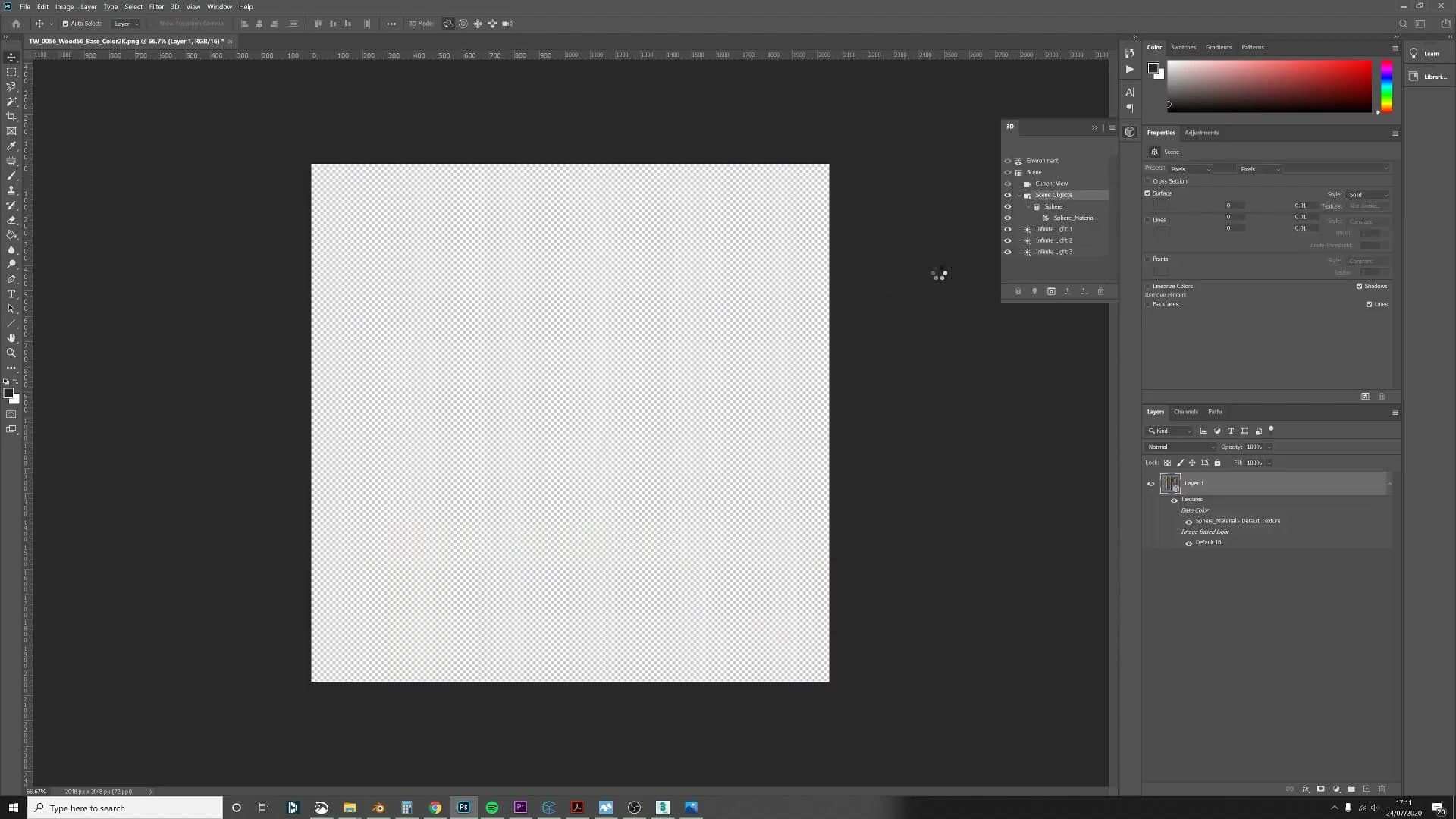
Open the colour texture in Photoshop and run Filter > 3D > Normal Map Generator. The filter produces a new normal map directly from the diffuse, picking up grain ridges and pore detail that the original veneer map was missing. Save the result, then point your Normal node's image input at the new file in Blender.
Back in the shader, the wood now reads with noticeably more depth under the lights. The bump is doing visible work along the grain instead of sitting flat against the surface.
Camera angle and depth of field
For the hero shot, position the camera at 90 degrees to the chair rather than the more typical three-quarter angle. The straight-on view foreshortens the curved frame in a way that flatters the silhouette and makes the woven seat pattern read clearly across the rectangle of the back.
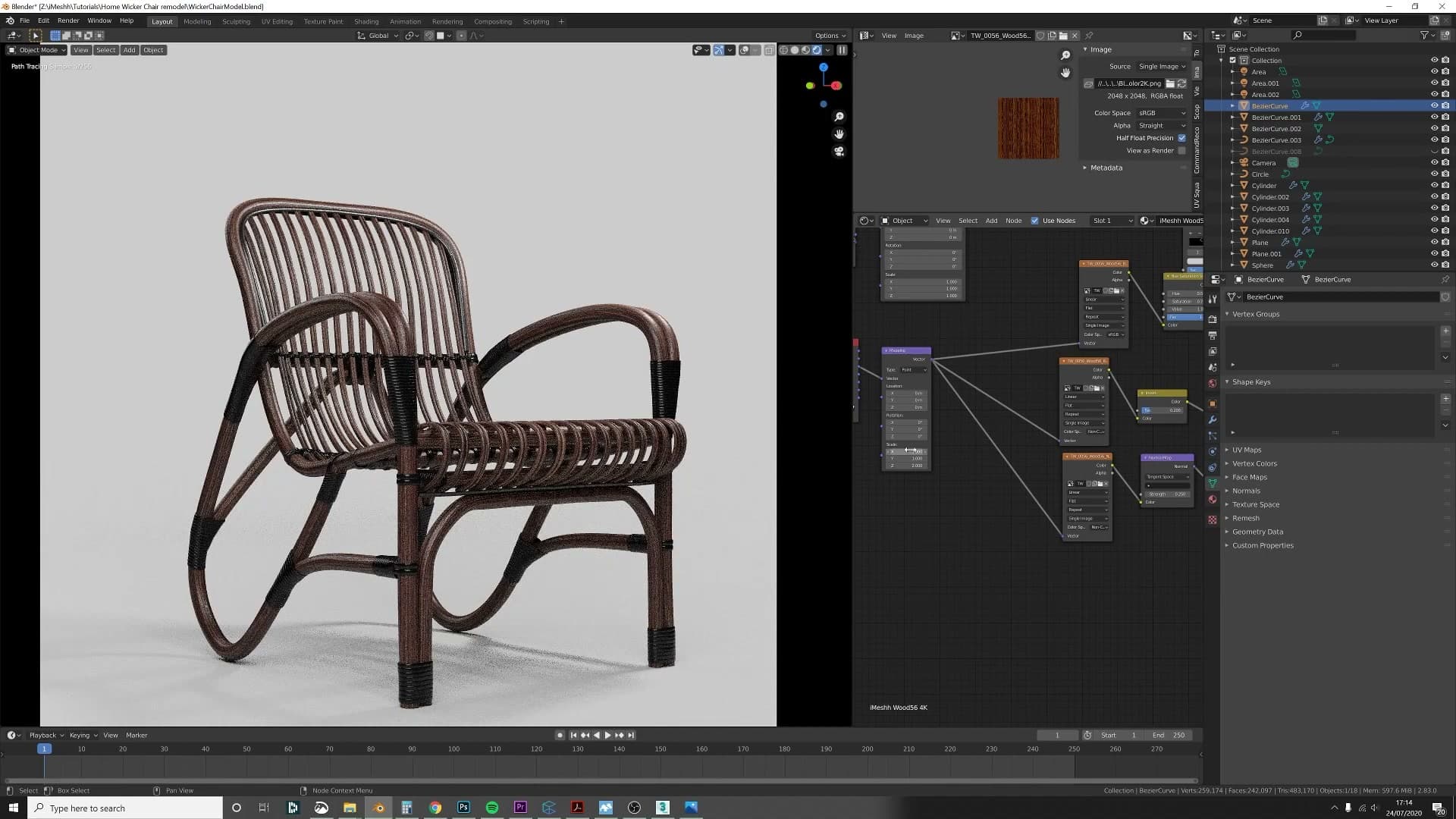
Enable depth of field on the camera and pick a focus point near the front leg or seat edge. The shallow falloff blurs the back of the chair just enough to add separation between the subject and whatever's behind it. A small detail, but it lifts the render out of looking like a turntable product shot.
From here, the work is iteration. Duplicate the camera, drop in a few alternative angles, and tweak the materials by small increments between renders until the wood, the rope binding, and the lighting all sit where you want them. The modelling is finished; everything left is composition and finish.
Tools and credits
Everything mentioned in this tutorial, with links.
- Blender (the renderer this entire build runs in).
- iMeshh (studio platform: project management, client review, asset library, invoicing). The asset library used in this tutorial is included with every iMeshh Pro plan.
- Poly Haven (free CC0 textures and HDRIs).
Pillar guide: Modelling hub