Why displacement is harder in Blender than it should be
A quick frame for the video: in Corona Render, displacement is a one-click operation. In Blender, getting good geometric displacement requires hopping between three different panels and knowing several non-obvious switches. We cover the Corona comparison and the terminology (micro-displacement, adaptive subdivision, true displacement) so the rest of the workflow makes sense.
The Corona one-click baseline
Displacement in Blender is harder than it has any right to be. People keep tripping over the same setup mistake, and even when you do everything correctly, the workflow is fiddly enough that it can trigger something close to a midlife crisis halfway through. Before we get into the Blender side, it helps to see what a sane displacement workflow actually looks like in another renderer, so you know what we are trying to match.
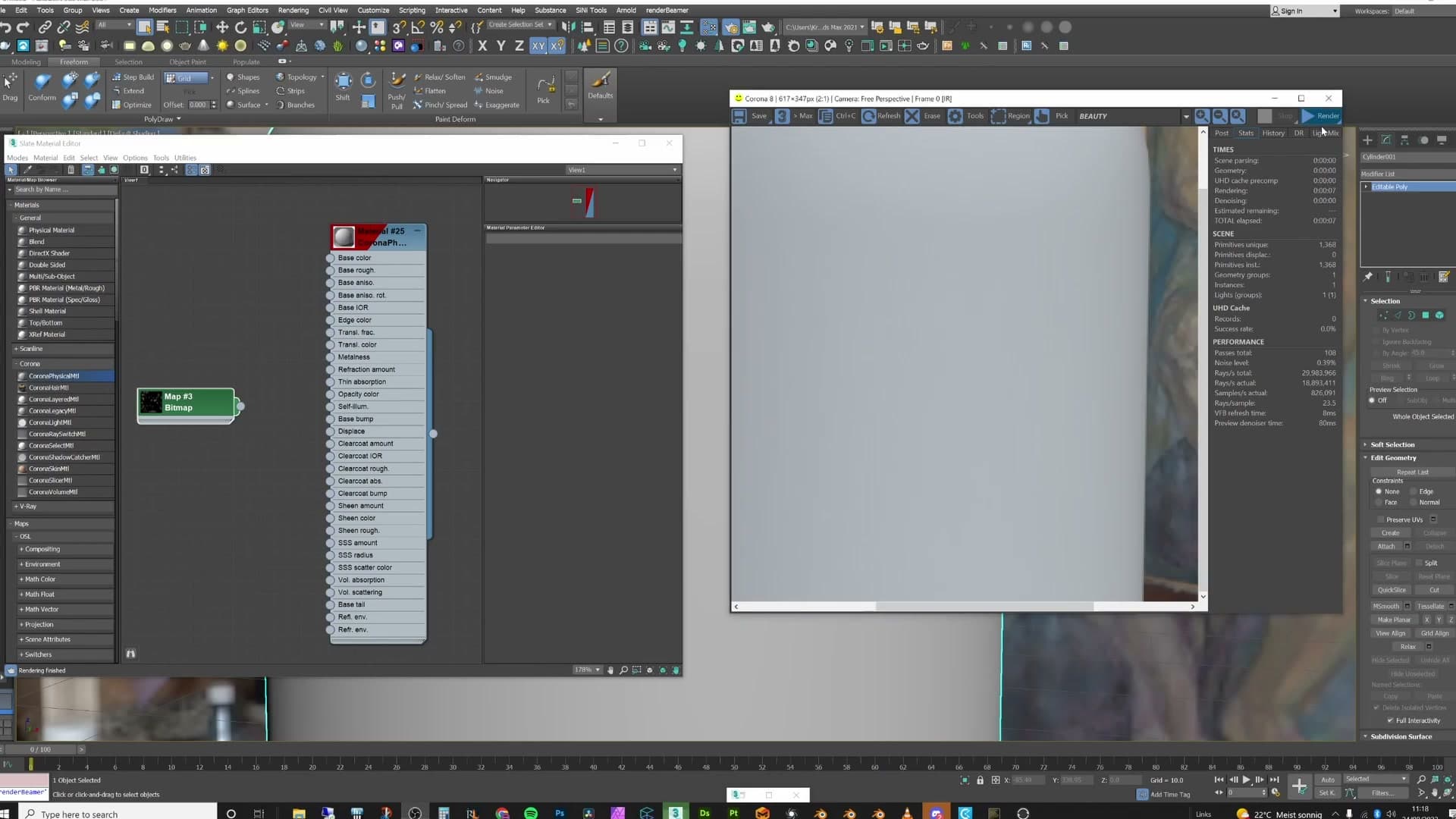
In Corona Render, the entire process is three actions. Load up a box, turn on the render preview, and plug a displacement map into the displacement slot. The geometry deforms, the silhouette breaks up, the texture's sharp edges carry through. Blender can do exactly the same thing, but you have to know which switches to flip and in which order. The rest of this post is about getting Blender to that one-click feel.
Micro-displacement, adaptive subdivision, and true displacement explained
When this post talks about displacement in Blender, it specifically means micro-displacement, also called adaptive subdivision. The two names describe the same feature: Blender dynamically changes the level of geometric detail in your mesh depending on how far the camera is from it. Close to camera, the mesh gets densely subdivided so the displacement is sharp; far away, the subdivision drops off and you save on performance. That distance-aware behaviour is the whole point. It's why you can use displacement on a full scene without the GPU melting.
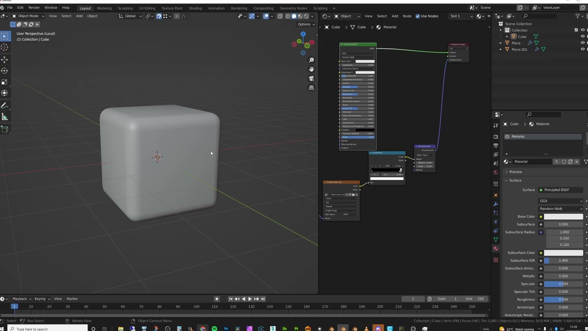
To see why this matters, take a striped texture. You want the displaced result to read as clean, raised stripes with crisp edges. Just dropping a Displacement node into the shader and wiring it up to a default plane doesn't get you there.
What you get instead is barely any deformation at all. The shader is asking for sharp ridges, but the underlying geometry doesn't have enough vertices to push around, so the silhouette stays nearly flat and the texture's sharp edges are lost in the process. The displacement isn't broken. The mesh just can't represent it.
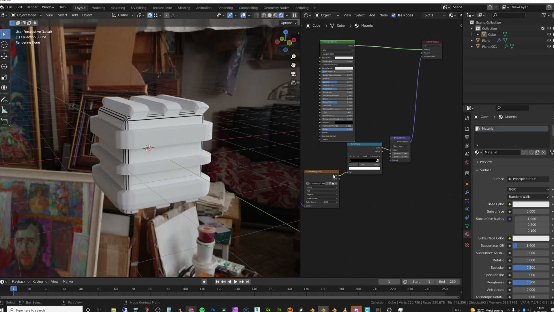
The brute-force fix is to add geometry by hand: loop cut a few extra divisions, jump into edit mode, right-click and subdivide a few more times. Do that enough and the edges do sharpen up; you start to see the striped pattern coming through. But you've had to throw a huge amount of geometry at a single plane to get there, and that approach falls apart the moment you scale it to a real scene. Adaptive subdivision is the feature that solves this properly, and that's what the rest of the video walks through setting up.
Setting up micro-displacement step by step
The actual setup. You need three things across three different panels: experimental Cycles, a subdivision surface modifier in Simple mode with adaptive subdivision turned on, and the material's Surface section set to either Displacement Only (true geometric, memory-hungry) or Displacement and Bump (the practical default). Then a single Displacement node wired into the material output's Displacement socket.
Enable the Experimental feature set in Cycles
Open Render Properties and change the Feature Set from Supported to Experimental. Adaptive subdivision lives behind this switch and won't appear in the modifier panel until you flip it.
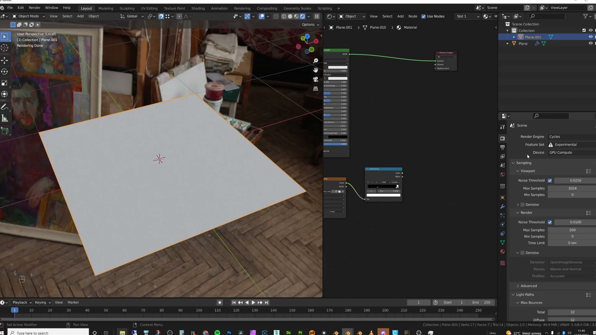
It's worth a small chuckle that this is still called experimental. Adaptive subdivision has been sitting behind the Experimental toggle since Blender 2.79, so by now it's about as battle-tested as any production feature, even if the label suggests otherwise. Treat it as a normal step rather than a risky one.
Add a subdivision surface modifier in Simple mode with adaptive subdivision
With the object selected, add a Subdivision Surface modifier. By default it'll switch to Catmull-Clark and try to smooth your topology, which you don't want. The mesh you've already built is fine; you just need extra geometry on top of it for the displacement to push around.
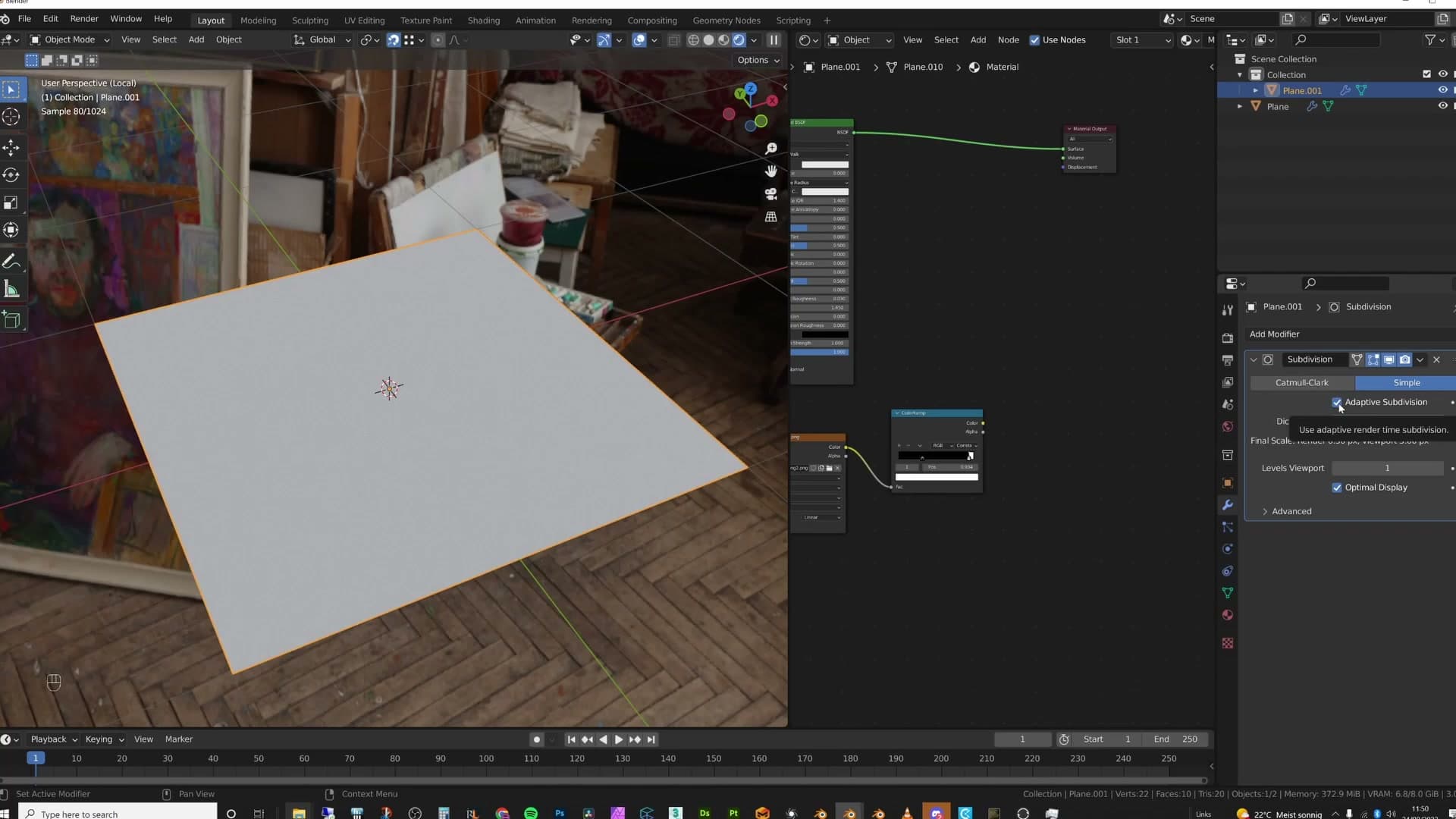
Switch the modifier type to Simple. That keeps the existing shape intact and only adds subdivisions, instead of rounding off corners and softening edges that were meant to stay sharp.
At the bottom of the modifier panel, tick Adaptive Subdivision. This is the part that does the work at render time: Cycles dices the mesh dynamically based on how close it is to the camera, so distant geometry stays light and anything in the foreground gets the density it needs.
Choosing between Displacement Only and Displacement and Bump
Go to Material Properties, scroll all the way down to the Surface settings, and find the Displacement dropdown. This is the control that tells Cycles how to interpret whatever you wire into the material output's Displacement socket.
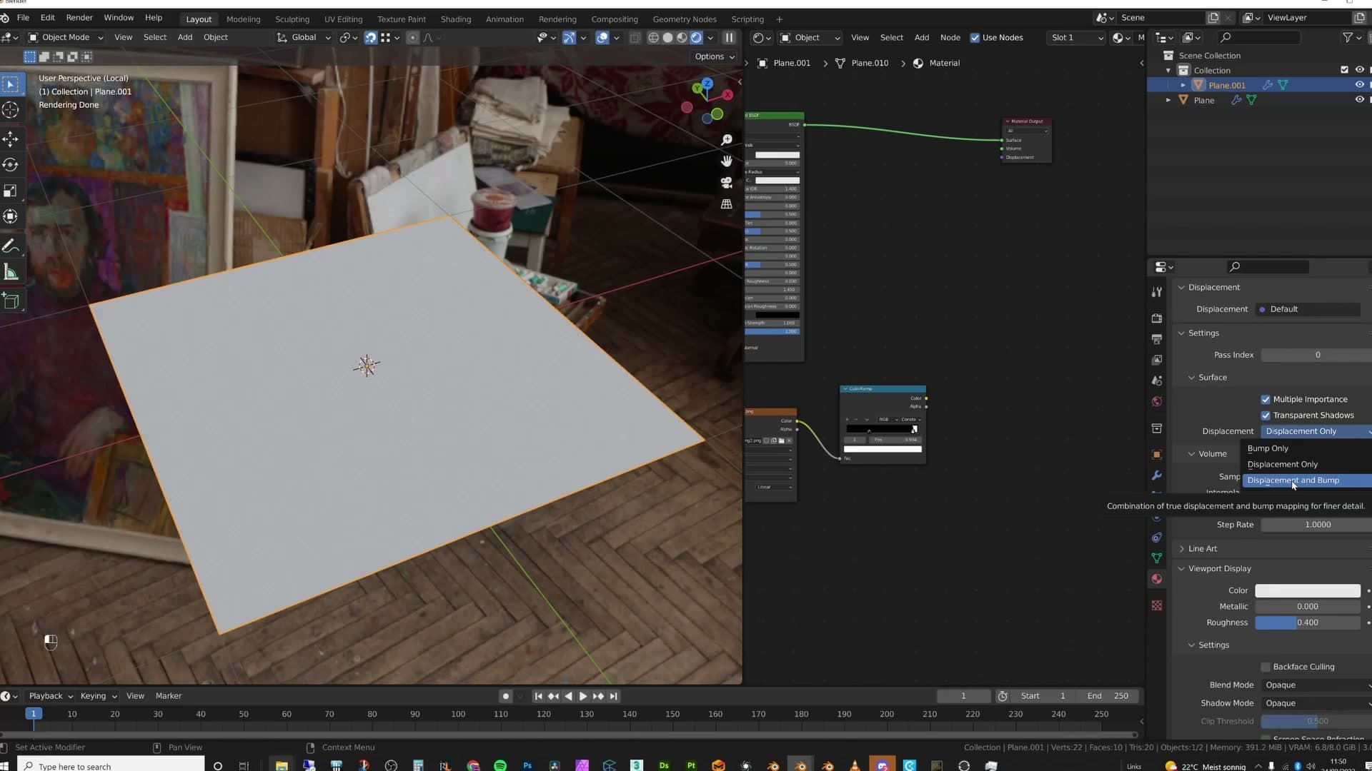
Displacement Only is true geometric displacement. Every detail in your map becomes real geometry pushed in or out of the surface, which gives you the most accurate result but also gets memory-intensive quickly, especially on dense textures and large surfaces.
Displacement and Bump is the optimised hybrid and the option you'll want most of the time. The displacement handles the overall shape (the big lumps and shifts in the surface) while a bump map drives the fine details on top of it. You get the silhouette benefits of real displacement without paying for every tiny variation in geometry.
If your material doesn't have a separate bump map plugged in, Displacement Only is the honest choice for the tutorial here, because there's nothing else doing the fine detail. The general rule, though, is Displacement and Bump unless you have a specific reason to go full geometric.
Wire the Displacement node into the material output
Open the shader editor and press Shift+A to bring up the Add menu, then either browse to Vector → Displacement or start typing displacement in the search to drop the node in.
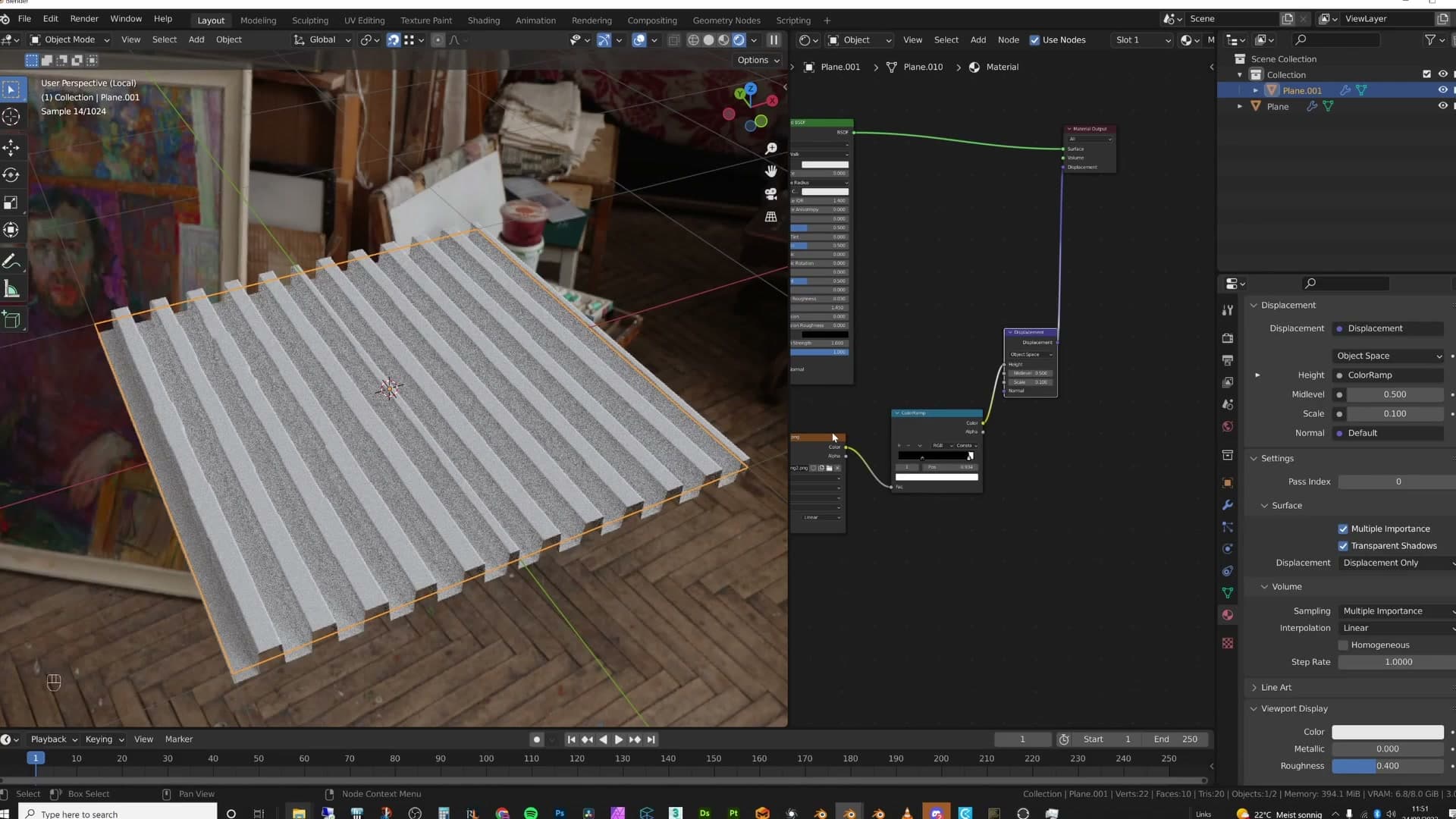
Wire your displacement texture's colour output into the Displacement node's Height socket, then plug the Displacement node's output into the Displacement socket on the Material Output. That's the full chain: texture into Displacement node into Material Output.
Bring the node's Scale down to around 0.1. Displacement maps are usually authored at a unit strength that's far too aggressive for real-world archviz surfaces, so scaling down keeps the effect believable instead of having tiles look like cobblestones.
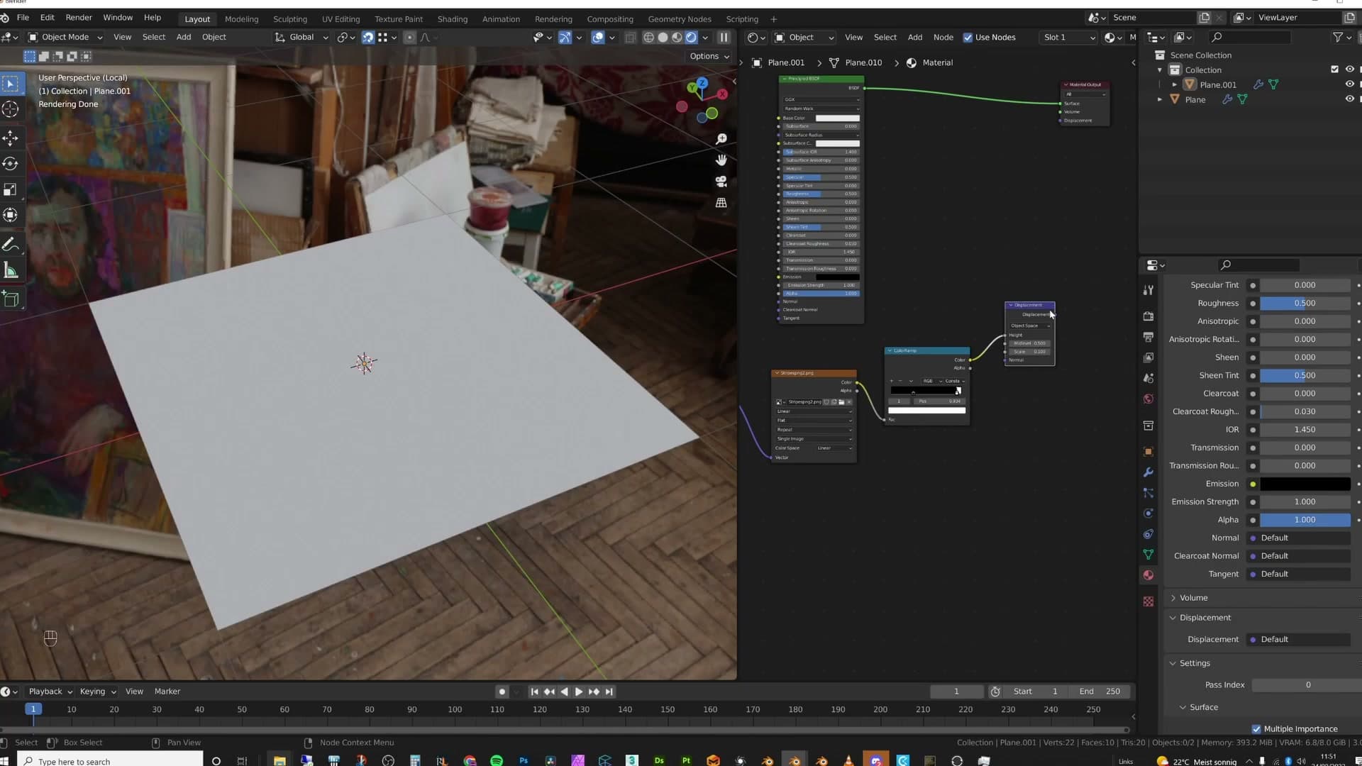
If your displacement map is a .exr file, set the image texture node's Colour Space to Non-Color (or Linear, depending on your Blender version). EXR data is already linear, so letting Blender apply an sRGB gamma curve to it crushes the height values and gives you wrong displacement amplitudes.
The dicing rate trap (and how it ruins your night)
Adaptive subdivision is governed by a Dicing Rate (viewport and render). Lower numbers mean finer subdivision and cleaner displacement, but the cost is exponential. A dicing rate of 1 is fine for almost everything. Drop to 0.5 and you watch your GPU melt. We walk through the setting, what 'render' versus 'viewport' actually do, and why going below 1 is almost never worth it.
Finding the dicing rate and what it actually controls
With adaptive subdivision switched on, the new control you need to know about is the Dicing Rate. It lives under Render Properties → Subdivision, and Blender exposes two values: one for the viewport, one for the render.
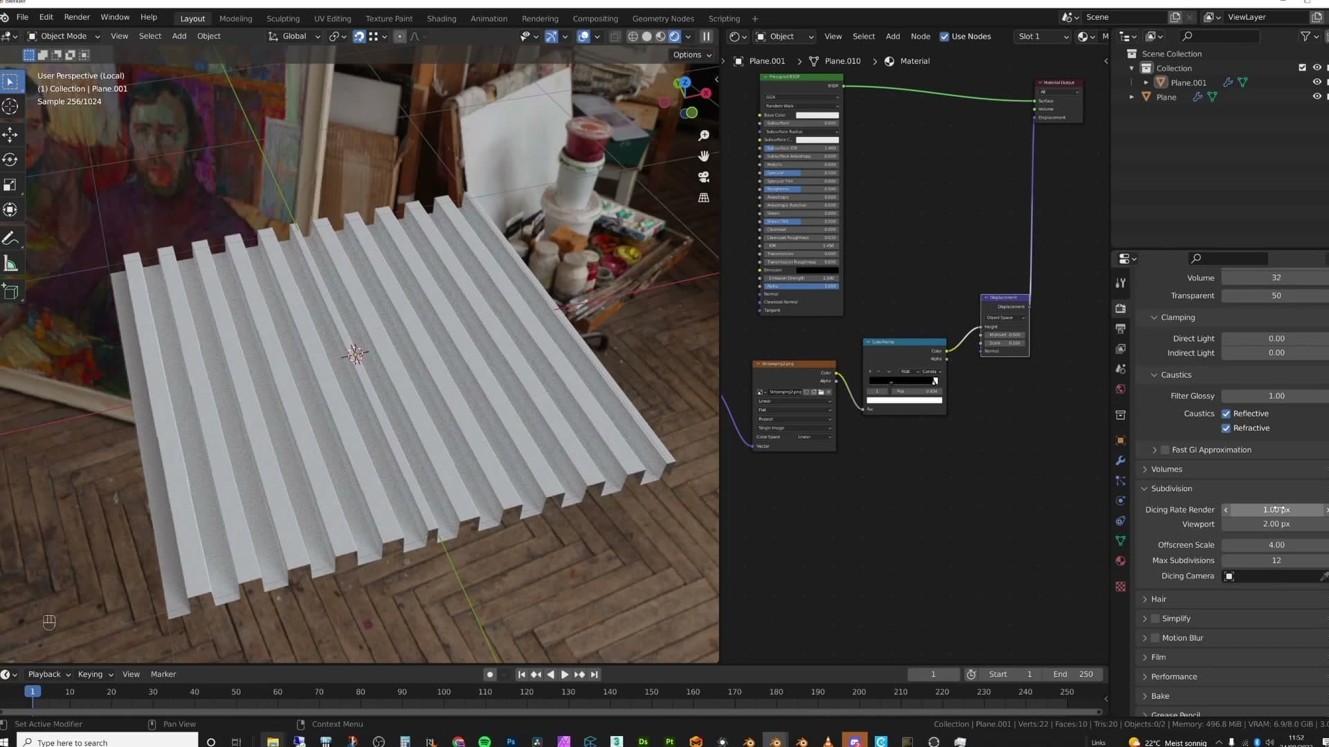
The viewport rate exists so you can keep working without choking your interaction speed. A higher number means coarser subdivision and a more fluid scene to push around. The render rate is the one that actually controls the geometry density in your final image: lower numbers dice more finely and give cleaner displacement, but the cost climbs quickly.
By default the two are set to roughly 1 for the render and 8 for the viewport. Drop the viewport down to around 2 while you are checking your displacement and you will already see the surface tidy up. For the render dicing rate, leave it at 1. That is the sweet spot for nearly every scene you are ever likely to build.
The life crisis that follows a 0.5 dicing rate
To drive the point home, the video takes a short detour into what actually happens after you ignore the advice and push the render dicing rate down to 0.5. It is worth preserving, because the lesson underneath is the entire reason the previous setting matters.
Your GPU melts mid-render. Your client phones at that exact moment to say they need the renders by the evening. You cannot deliver. The job is cancelled. Without the income you cannot replace the machine, so the work dries up, then the rent goes unpaid, and the landlord eventually kicks you out.
Your family moves in with the in-laws for some loving support. You cannot bring yourself to face them, so you end up in a little junkyard caravan and the bottom of a bottle starts looking like the only friend you have left. A mysterious figure in a long trench coat sells you something stronger in a dingy alley, and from there the spiral is downward and fast: crime to pay for the next fix, no friends, no fixed address.
Then your old school friend Carl finds you passed out in a park, takes you home without asking questions, feeds you, and tells you that you can stay as long as you need. Weeks go by. You get cleaner. One evening you pick up his laptop, find a tutorial on Blender displacement, and swear an oath: never set the subdivision dicing rate below 1. You hit render. It works. For the first time in a long time, you tilt your head down with a smile and think, I have done it.
And then you look a little closer at the result, and something is still not quite right. The displacement looks a touch odd. Which is where the next problem begins.
The n-gon mistake nobody talks about
The most common displacement bug in arch-vis isn't bad maps or wrong settings. It's topology. When you trace a floor plan, press F to fill, unwrap, and apply a tile or plank displacement, the floor is a single n-gon. Blender's adaptive subdivision triangulates that n-gon into chaotic strips that have nothing to do with the texture's straight lines. The result is jagged edges that you'll try to fix by lowering the dicing rate (see previous module re: GPU). The real fix is to add loop cuts that turn the n-gon into quads aligned with the texture direction.
Recognising the jagged-floor symptom
This is the displacement bug you keep seeing in arch-vis scenes, and the people running into it usually don't realise what is actually causing it. The setup is identical every time. You import a CAD floor plan, select the traced outline with A, fill the face with F, unwrap it, and apply a displacement map of tiles, bricks, or terrace planks.
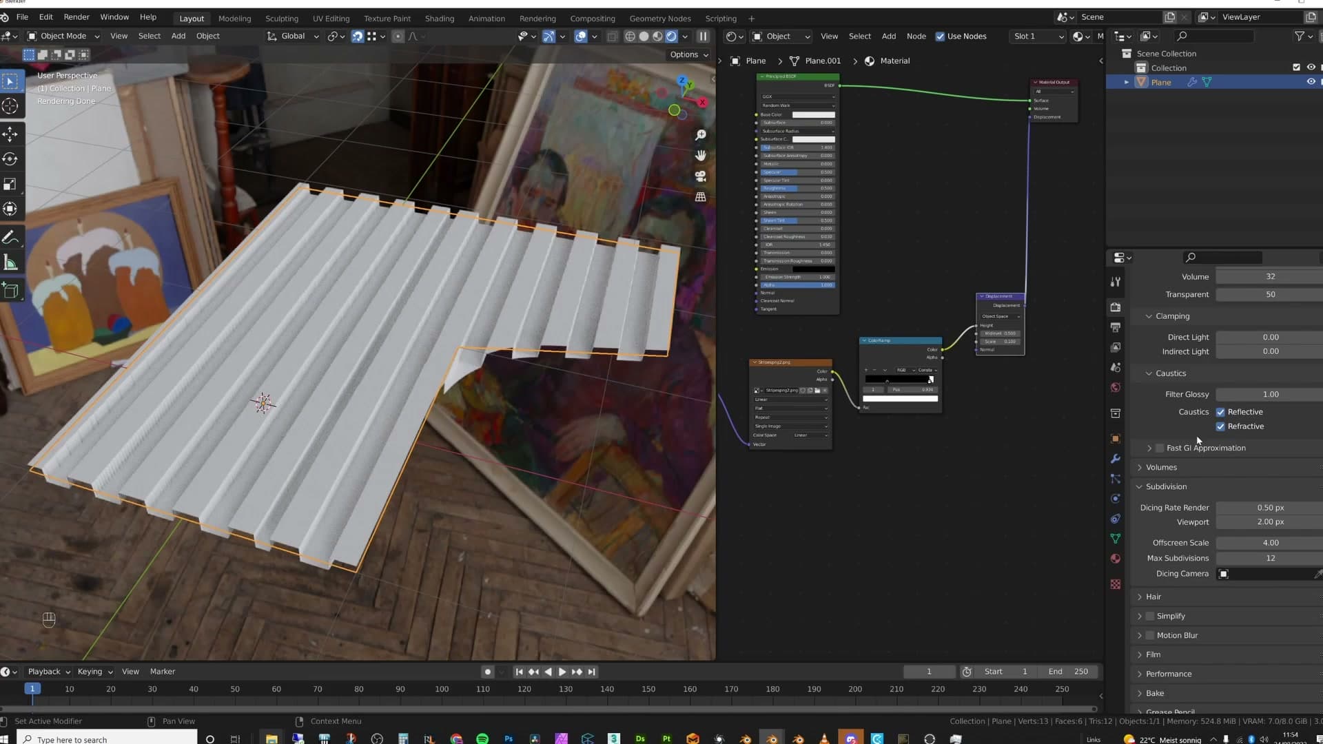
Set the render dicing rate to a sensible value like 4 and the floor lights up with jagged edges. The lines run at random angles, the result is anything but uniform, and the obvious instinct is to drop the dicing rate until the edges smooth out. Even at 2 the floor is still riddled with them. That is the moment most people start chasing the problem in the wrong place.
Why n-gons shred straight-line displacement maps
Adaptive subdivision works in two passes. First it subdivides the mesh, then it uses that subdivided geometry to push the surface up and down according to the displacement map. The result is only as clean as the geometry it had to work with, and a single filled n-gon is not clean geometry.
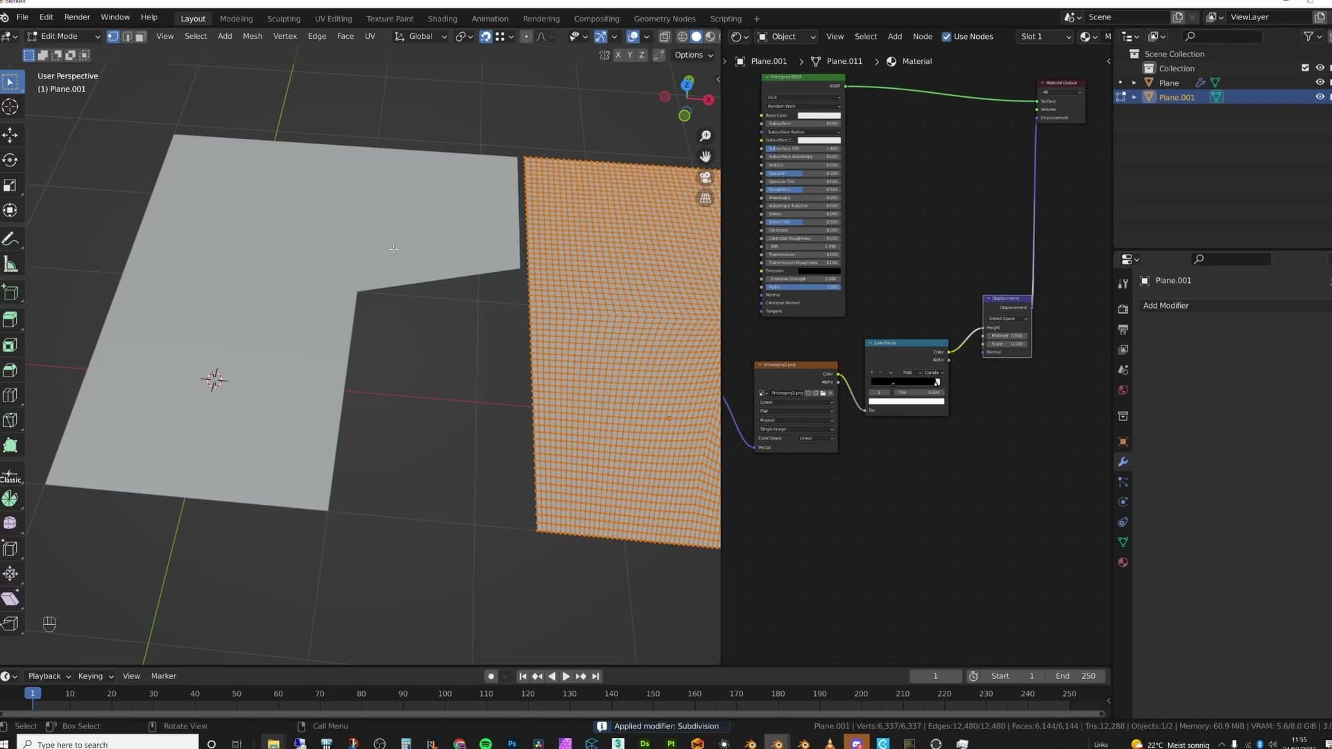
To see what Blender is actually doing under the hood, turn adaptive subdivision off, switch the subdivision surface modifier to a fixed level like 6, and apply it. The whole floor is suddenly carved into triangles running in every direction. Not a single one of those internal edges is straight.
That is the problem. A terrace floor, brick, or tile map has straight lines following the texture's grid, and Blender is trying to push that straight-line displacement through a mesh whose internal edges run at every angle. The silhouette of each tile follows the chaotic triangulation instead of the texture, and at dicing rate 2 you still see it. No amount of dicing-rate tweaking will rescue you here. The geometry itself is fighting the map.
Fixing topology with loop cuts and vertex joins
The fix is topology. Give the floor edges that already run parallel to the texture's direction and adaptive subdivision suddenly has clean quads to subdivide instead of one chaotic face.
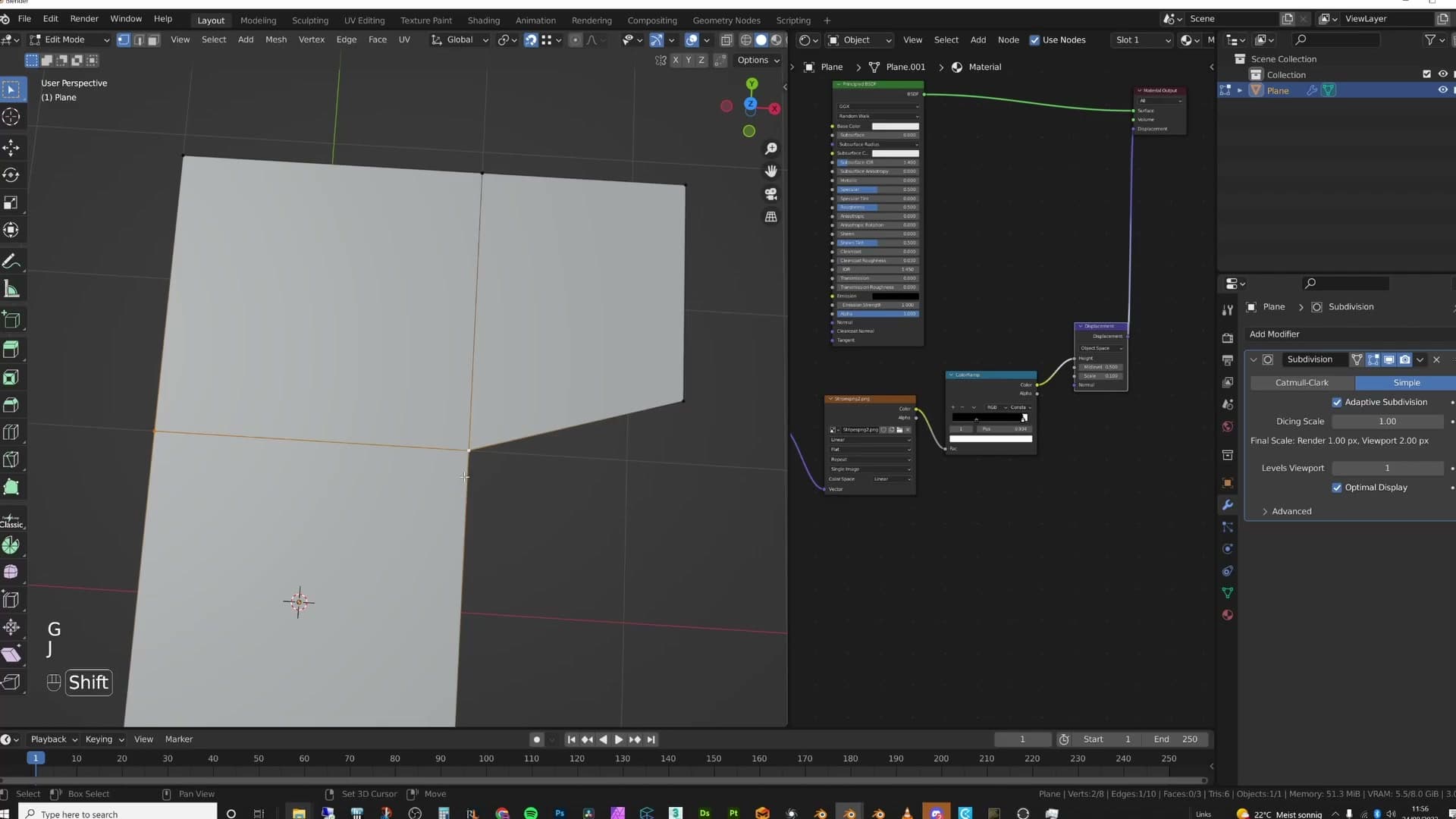
Tab into Edit Mode on the floor and add a loop cut across the n-gon with Ctrl+R. With snapping enabled (toggle it with Shift+Tab), press G G to slide that new edge along until it sits where you want it. Select the two vertices you want to bridge across the face and join them with Shift+J. Repeat across the floor until the single n-gon has been broken up into quads that follow the displacement's straight lines.
The goal is not to add dense geometry. It is to add the right geometry. A handful of loop cuts aligned to the tile direction is enough; the topology should mirror the way the texture itself runs.
The cleaned-up displacement result
With the topology sorted, push the render dicing rate back to a reasonable 4 and look at the floor again. A few edges might still look slightly jagged where the mesh sits further from the camera (adaptive subdivision dialling resolution down by distance, exactly as it should), but the chaotic, broken silhouette is gone.
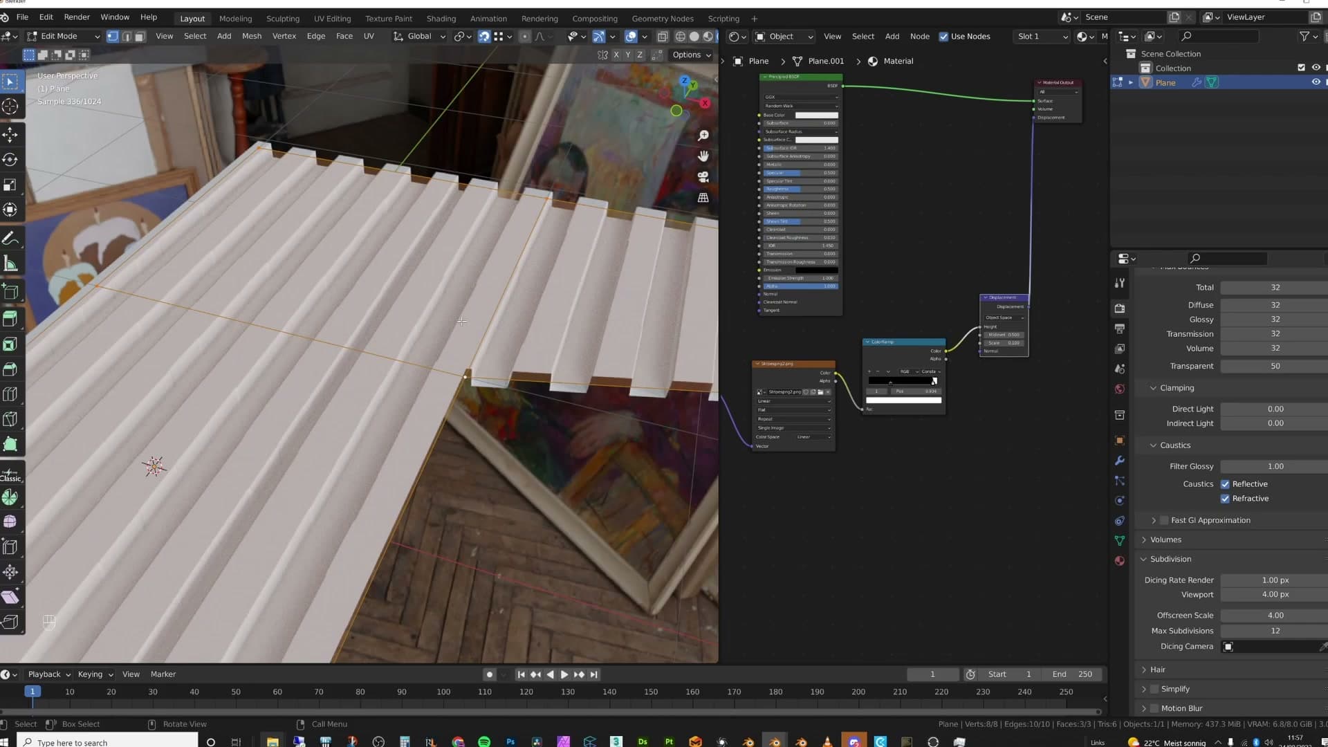
If you want proof it is the topology doing the work and not the dicing rate, select the floor and run a Limited Dissolve to strip out the inner edges. The face collapses back to an n-gon and every jagged edge floods straight back in. Undo it, the new topology returns, and so does the clean displacement. Same map, same dicing rate. Only the mesh has changed.
When the geometry is subdivided uniformly along the texture's direction, adaptive subdivision is handed a grid that matches the displacement map and the straight lines come through cleanly. Leave the floor as a single fat n-gon and the only lever you have left is the dicing rate. That is how scenes end up at 0.5 and your GPU ends up cooked.
It is one of the most common displacement bugs in archviz scenes, and one of the simplest fixes once you can actually see what is going on.
The principle: topology should follow the texture
The takeaway is one line. Even with adaptive subdivision doing the heavy lifting, your base mesh should still flow in the same direction as the displacement pattern. Square tiles want a square grid. Diagonal herringbone wants diagonal cuts. Get that right and you can keep the dicing rate at a sane 1.
Match mesh direction to texture direction
The rule to carry out of this video is simple: even when adaptive subdivision is doing the work, your base mesh still needs to flow in the direction of the displacement map. The subdivider can only cut what's already there, so if the topology underneath fights the texture, you'll see the fight at the edges.
Match the grid to the pattern. Square tiles or straight wood planks want a clean, rectangular grid running along the same lines as the texture. A diagonal pattern, like a herringbone or any displacement that runs at an angle, wants loop cuts that mirror that diagonal so the resulting quads sit parallel to the texture's lines.
Get that alignment right and you can stop chasing the problem with the dicing rate. There's no need to push the value down dangerously low to mask jagged edges. A sensible grid that follows the texture lets adaptive subdivision do its job at a normal setting, with no errors and no melted GPU.
Tools and credits
Everything mentioned in this tutorial, with links.
- Blender: the renderer this entire build runs in.
- iMeshh: studio platform (project management, client review, asset library, invoicing). The asset library used in this tutorial is included with every iMeshh Pro plan.
- Poly Haven: free CC0 textures and HDRIs.
Pillar guide: Texturing Displacement hub