Planning the side arches, floor and water
Block out what still needs to be added to the scene before lighting and materials begin: the side archways, a floor plane, a water surface and a back wall.
What still needs modelling before lighting
Before you can move on to lighting and materials, the scene still needs a few structural pieces in place. The centre archway from the previous part is there, but the surroundings are empty — so this part is about filling them in. You'll add the side archways flanking the centre, a floor plane underneath everything, a water surface where the foreground pool will sit, and a back plane against the rear wall to close the scene off.
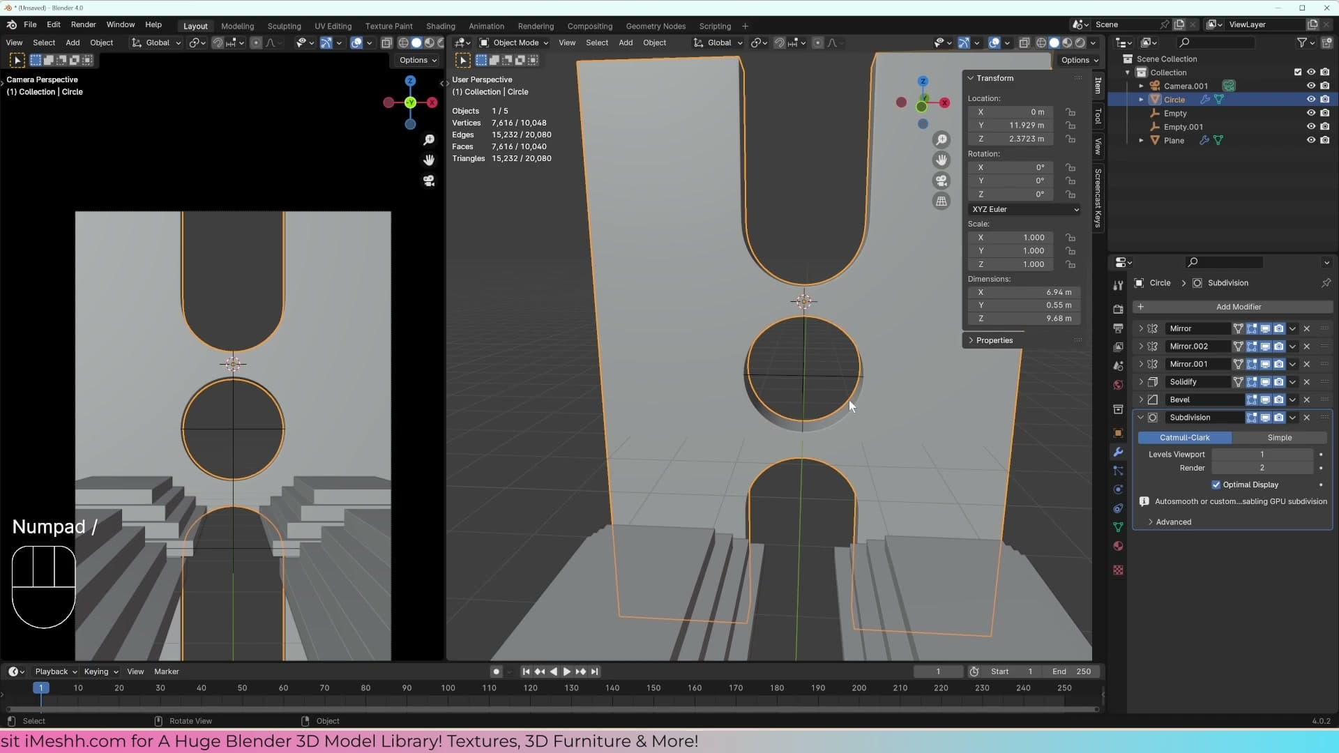
Once those four elements are blocked in, the cathedral-style space starts to read as a finished environment rather than a single arch floating in the void, and you'll have something solid to light against in the next part.
Rather than modelling the side arches from scratch, you'll reuse the centre archway you already built. It has the full modifier stack on it already — Mirror, Solidify, Bevel and Subdivision Surface — so duplicating it gives you matching geometry in seconds. Drop into local view on the duplicate so you can isolate it and work on the shape without the rest of the scene getting in the way.
Duplicating the existing archway for the sides
Reuse the centre archway as the starting point for the side arches. Duplicate it, isolate it with local view, strip the unneeded modifiers, and meet your first encounter with Z-fighting.
Isolate the archway with local view
Duplicating the centre arch with Shift+D brings the geometry across with its full modifier stack still attached. Before doing anything else, tap Numpad / to drop into local view. That hides every other object in the scene so you can edit the new arch without the rest of the cathedral getting in the way.
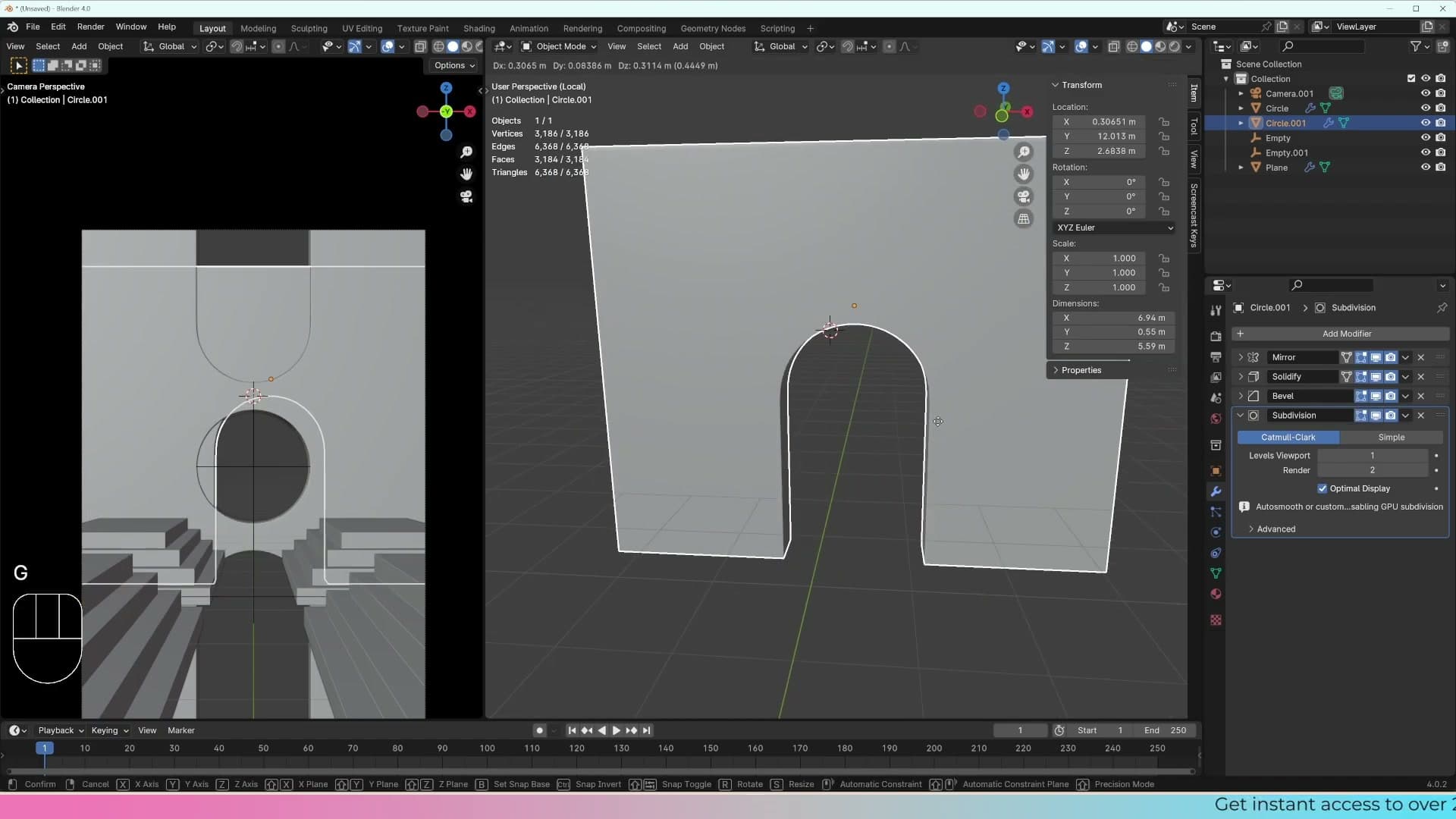
The duplicate inherits more modifiers than the side arches actually need. Open the modifier panel and strip off the top two entries, but keep Solidify, Bevel and Subdivision Surface. Those three give the arch its thickness, rounded edges and smooth shading, and they're worth carrying over as-is.
Press Numpad / again to come back out of local view. The duplicate rejoins the scene alongside the original arch, ready to be moved into position.
Z-fighting and rotating the arch into position
The moment the duplicate lands on top of the original you'll see a flickering shimmer across the overlapping surfaces. This is Z-fighting: two faces are sitting in exactly the same space and Blender can't decide which one should be drawn in front, so it switches between them on every redraw. It looks like a render glitch, but it's a geometry problem, not a bug.
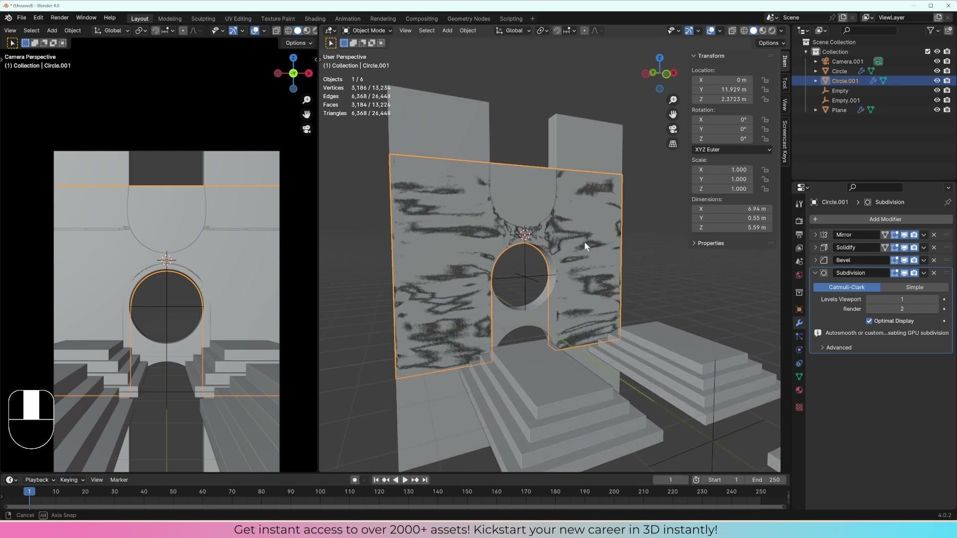
The fix is simply to move one of the faces. Drag the duplicate away from the original and the shimmer disappears the instant the two surfaces stop overlapping.
To form the side opening of the cathedral, rotate the duplicate ninety degrees around its vertical axis with R, Z, 90, Enter. Slide it out to the side of the centre arch and lift it up so it sits roughly where the side wall needs to be. Exact placement can be tweaked later.
There's a leftover edge running across the inside of the arch that's producing a slightly ugly shading line. Select that edge and dissolve it. The shading still isn't completely clean afterwards, but this part of the arch sits where the camera won't see it, so it's not worth chasing further.
Mirroring with the 3D cursor as the pivot
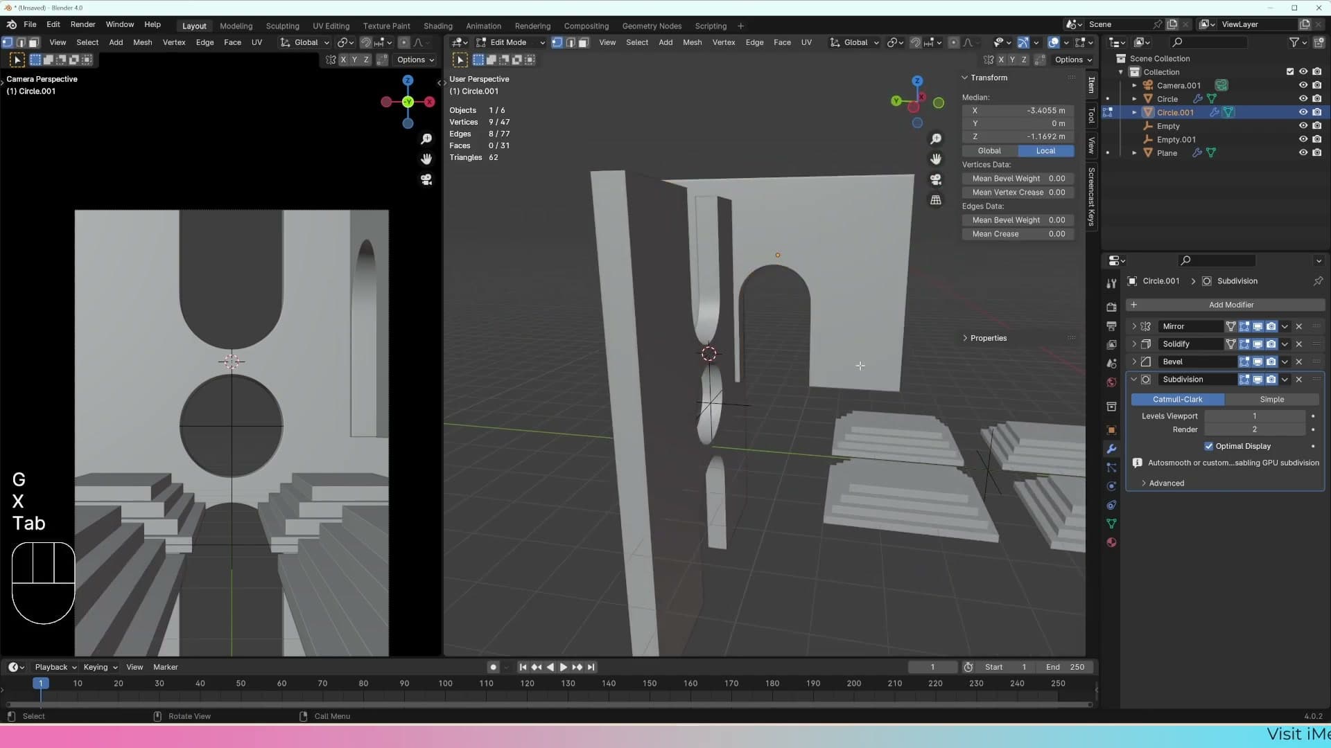
Drive the Mirror modifier from an exact edge by snapping the 3D cursor to a selection, then setting the object origin to that cursor. Then enable Clipping to weld the seam.
Shift+S to Cursor, then Set Origin → 3D Cursor
By default the Mirror modifier pivots around the object's origin, which is rarely the edge you actually want as the seam. To force it to flip across a specific edge, you move the origin to that edge first. The way to do it cleanly is via the 3D cursor.
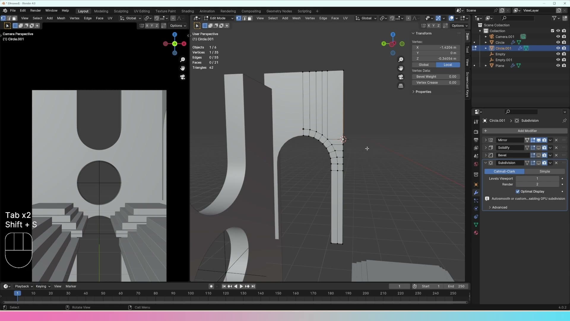
In edit mode, select the edge you want to act as the centre line. Press Shift+S and pick Cursor to Selected. Blender snaps the 3D cursor to the midpoint of the selection.
Drop back to object mode, right-click in the viewport, and choose Set Origin → Origin to 3D Cursor. The object's origin pin jumps onto that edge.
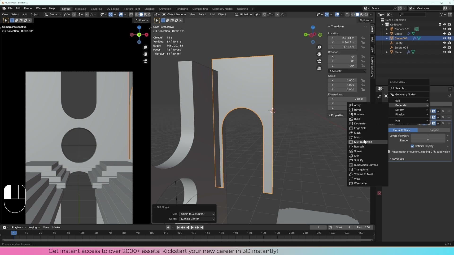
If you already had a Mirror modifier on the object, it will look broken the moment the origin moves. It's still flipping geometry, but now from the new pivot. Apply that old modifier first so the existing half-and-mirror bakes down into a single solid mesh. Then add a fresh Mirror modifier (Generate → Mirror). With the origin sitting exactly on the seam, the new mirror flips the whole shape cleanly across that line.
Enable Clipping so the centre edges weld together
With the new Mirror modifier in place, press A to select everything in edit mode and G to drag the half toward the centre. As the two mirrored sides slide together the faces start overlapping each other, which is the kind of mess that causes shading glitches further down the line.
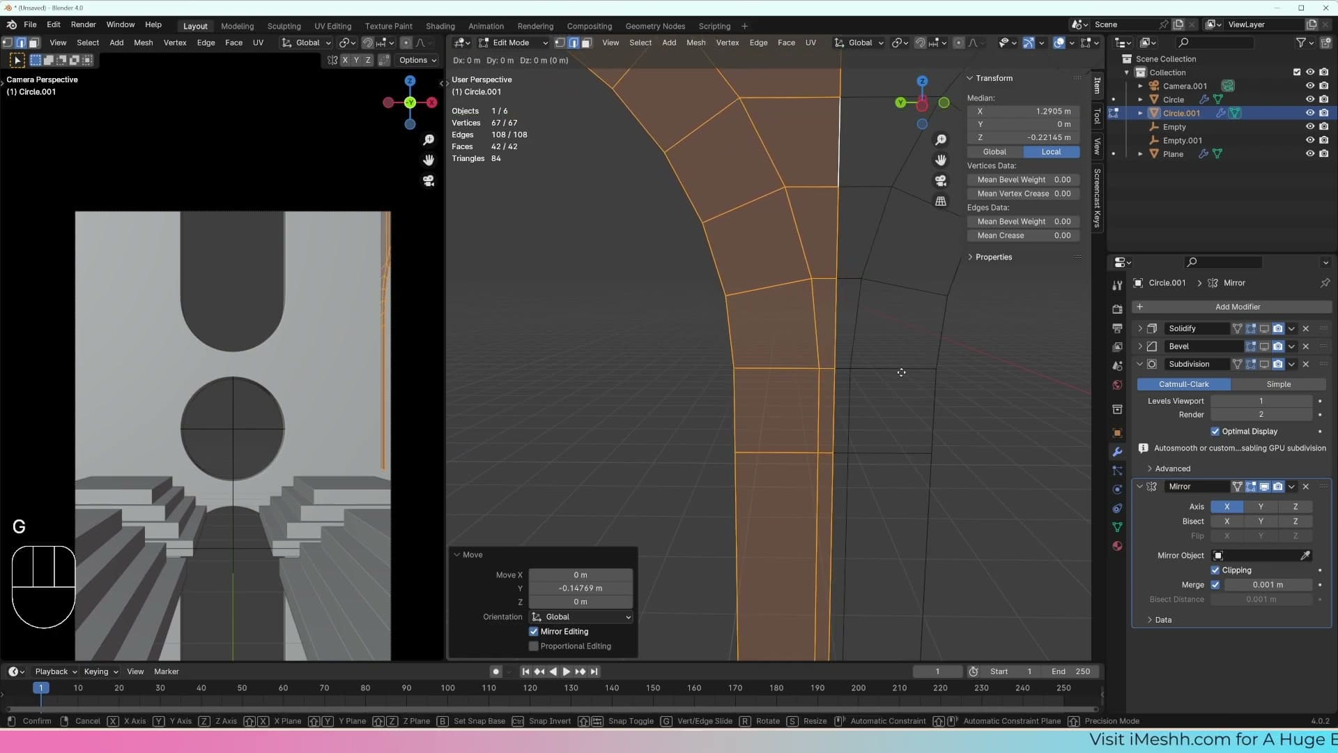
The fix is in the modifier itself: open the Mirror modifier and tick Clipping. Any vertex that touches the mirror plane is now pinned in place. It physically cannot cross over into the other half. Push the mesh in as far as you like and the two sides will simply meet and weld along the seam instead of intersecting.
Don't try to force every vertex right onto the mirror line, though. If three or more points end up stacked on top of each other you'll get overlapping edges, which Blender will happily render but tends to throw shading errors on. Leave a small breathing gap rather than crushing everything to zero.
Modifier stack order: merge vertices, then reorder
Track down the strange shading at the join: overlapping vertices are confusing Solidify. Fix it with Merge by Distance, then move Mirror to the top of the stack so Solidify, Bevel and Subdivision Surface run on the joined mesh instead of each half separately.
Why Solidify is producing weird shading
With Solidify now active, the seam down the centre of the archway starts showing strange shading: dark patches and shimmering that don't match the rest of the surface. The modifier is doing what you asked, giving every face thickness, but at the join it can't decide which face should be thickened and which should be pushed away.
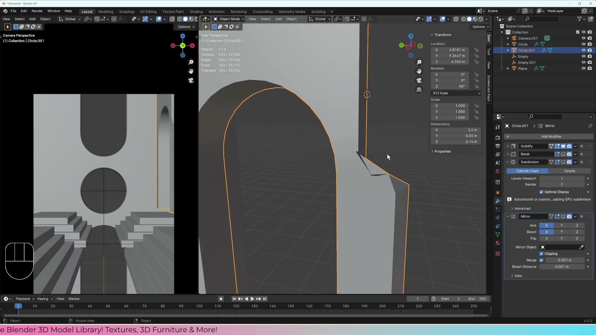
Drop into edit mode and the cause becomes obvious: there are overlapping faces sitting on top of each other along the centre line. Some edges are doubled up (edges on edges) and Blender doesn't handle that gracefully. Solidify hits the duplicate geometry, tries to push each coincident face out by the same amount, and produces the artefacts you're seeing.
A + M + By Distance to weld duplicates
The fix is to weld the duplicates together. In edit mode, press A to select every vertex, then M to bring up the Merge menu and choose By Distance.
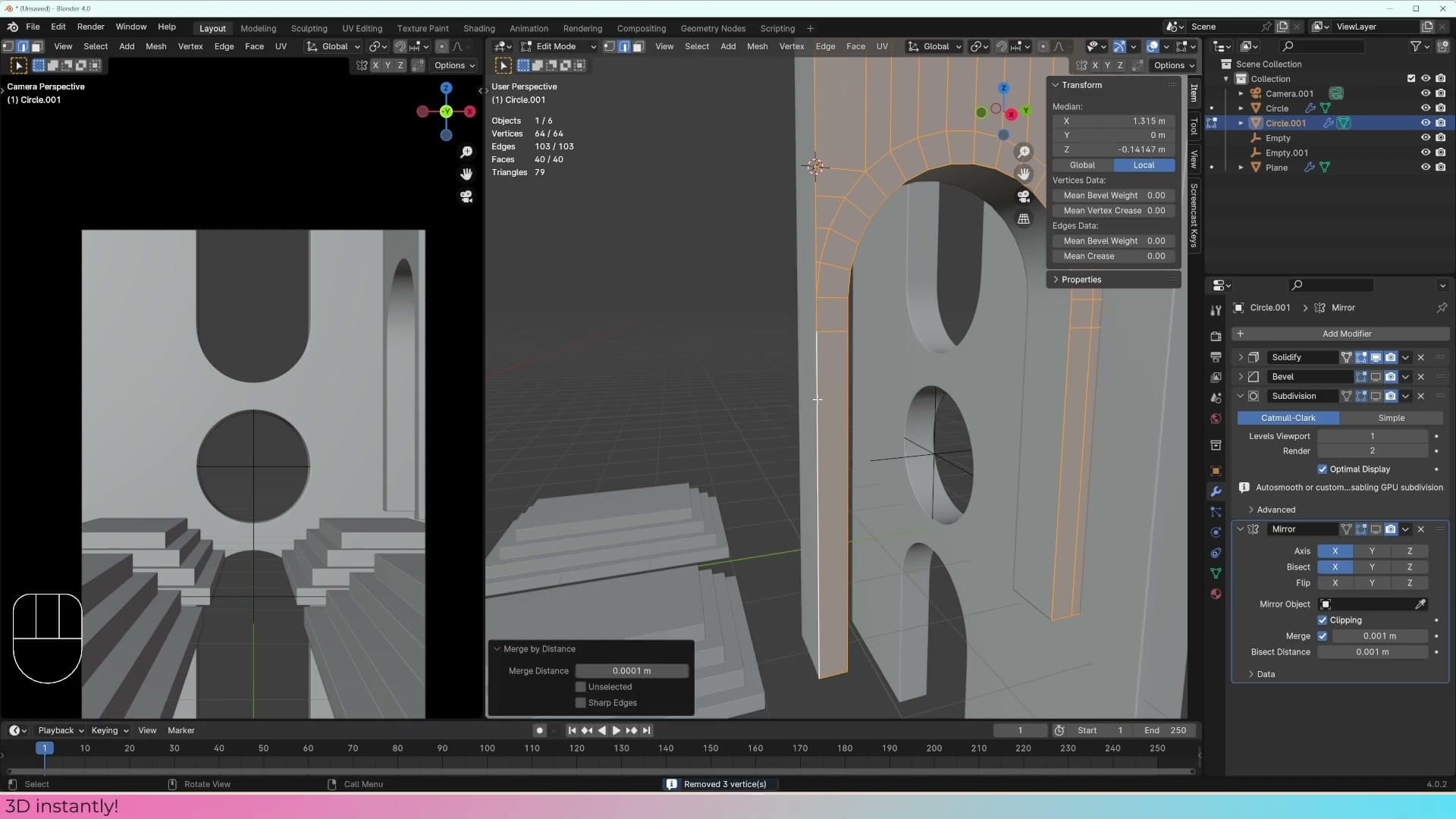
Blender's default tolerance is 0.0001 m. Any two vertices closer than a tenth of a millimetre get fused into one. A small operator panel appears in the bottom-left of the viewport reporting what happened: in this case it says three vertices were removed, which are exactly the duplicates that were sitting on the centre line.
You can drag the merge distance up if more vertices need to be joined, and you'll see more of the mesh collapse as the tolerance grows. Push it too far, though, and you'll start fusing vertices you wanted to keep separate. The default value is the right starting point for almost every cleanup job.
Mirror first, then Solidify, Bevel and Subsurf
Welding the duplicates cleans up the half you've been modelling, but there's a second problem waiting. If you add the Mirror modifier now, sitting below Solidify and Bevel in the stack, those modifiers run on the half-piece first, build an inside wall along what should be the join, and only then mirror the result. You end up with a visible seam straight down the centre of the finished shape.
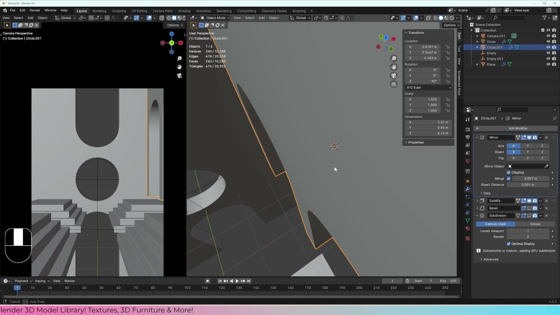
The order of the modifier stack matters. Drag the Mirror modifier to the very top so it runs first. Blender will then mirror the bare geometry, join the two halves into a single continuous shape, and apply thickness, bevels and smoothing to the merged result rather than to each half separately.
With Mirror at the top, Solidify has no internal wall to build because there is no internal edge. Both halves are part of one surface. Add Bevel back on top, then Subdivision Surface above that, in the same order they were in before. The shading along the centre line is gone and the archway reads as a single object.
Mirroring to the other side using an object reference
Add a second Mirror modifier and point it at the centre archway object. This mirrors the new side arch across the scene without needing to reposition the origin again.
Mirror Object: pivot from another mesh
You now have one side arch and the original centre archway, but the scene is still lopsided. You want a matching arch on the opposite side too. Rather than duplicating again and trying to position it by eye, you can lean on a second Mirror modifier and tell it to pivot from another object entirely.
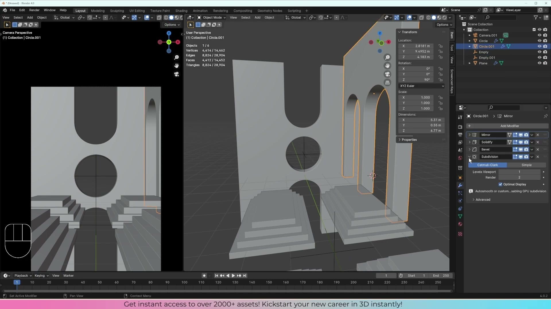
With the side arch selected, add another modifier from Generate → Mirror. This time, instead of relying on the object's own origin, click into the Mirror Object slot and pick the original centre archway. The modifier now mirrors across that object's origin rather than this one's. Because the centre archway is already sitting dead centre in the scene, the reflected copy lands exactly where it needs to.
A nice side effect of this setup is that the pivot follows the reference object. If you move the centre archway, both side arches shift around it in lockstep. It also doesn't matter that the centre archway's origin sits down at the base; the side arch geometry isn't anywhere near it, so the vertical offset has no visible effect on the mirror.
The cathedral shape comes together
Step back from the viewport for a moment. With the centre archway flanked by two matching side arches, the silhouette has finally tipped over into something that reads like a cathedral. It's a satisfying jump from three disconnected modifier stacks to a recognisable building shape, and you got there without modelling either side arch from scratch.
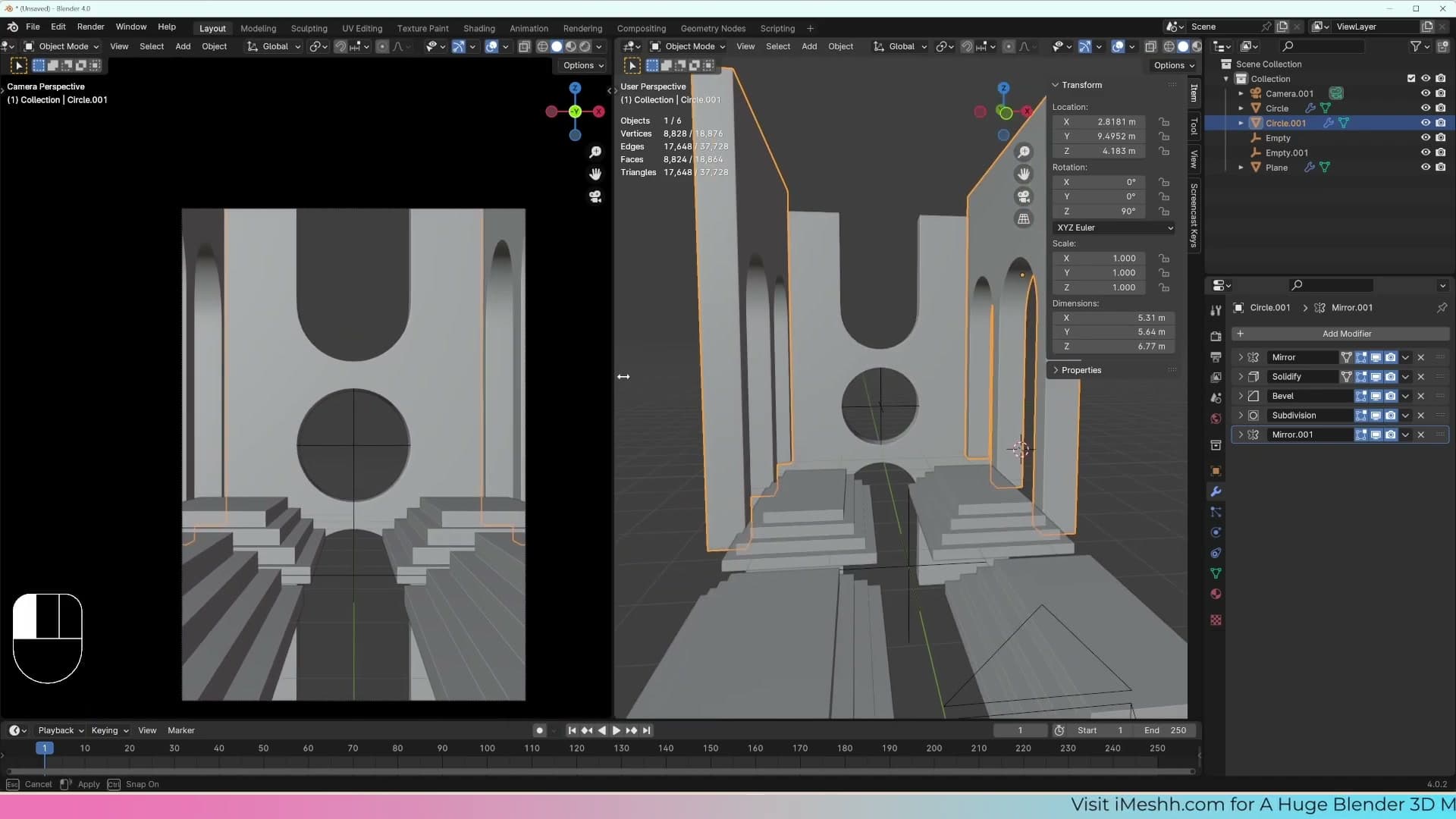
Next up, you'll start filling in the ground the cathedral sits on: a back floor and a back wall to give the scene somewhere to live.
Building the back wall and bottom floor
Duplicate the existing staircase plane to make the back wall at the right height, then drop in a simple plane as the ground floor under everything. Both pieces are quicker to build by reusing geometry you already have.
Duplicate the staircase to make the back wall
You already have a plane sitting at exactly the right height: the top of the staircase you built earlier. Rather than dropping in fresh geometry and trying to match that height by eye, it's quicker to duplicate what's already there.
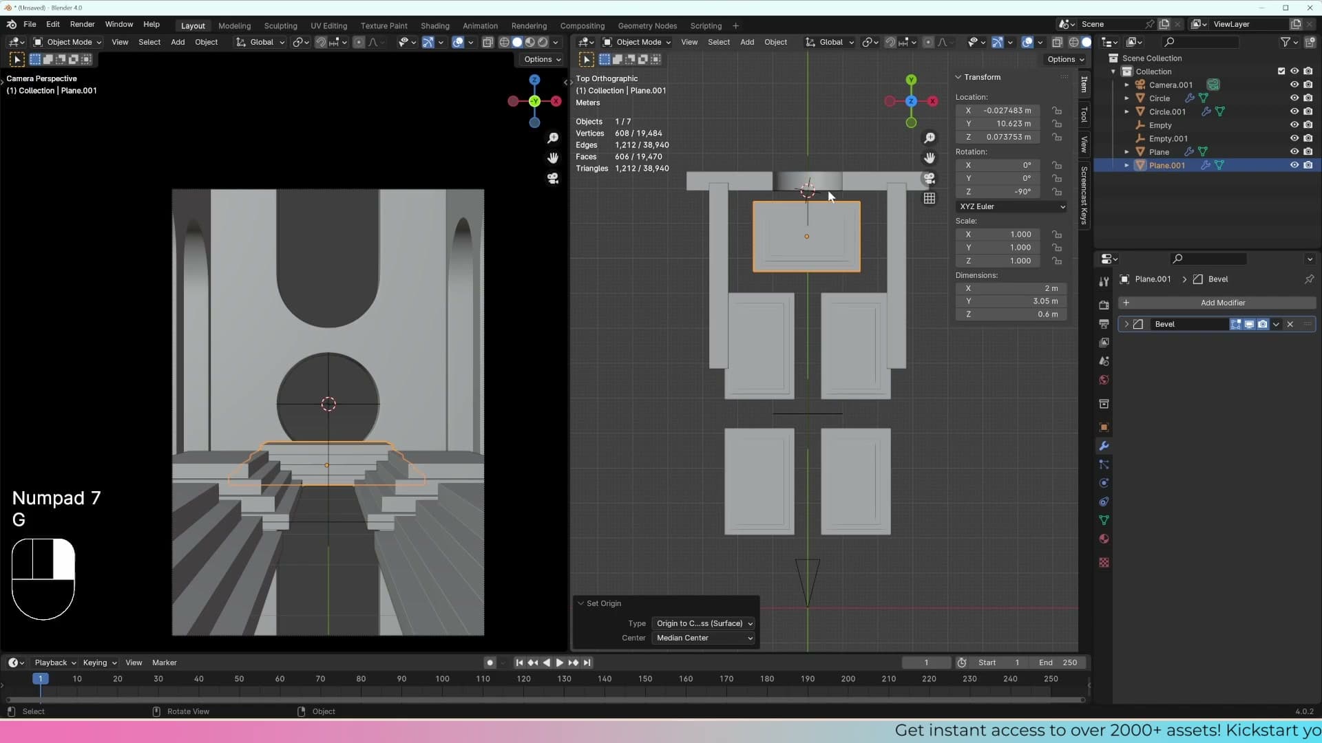
Switch to the top view, select the staircase, and press Shift+D to duplicate it. Press R 90 to rotate the copy ninety degrees so it spans the back of the scene. The duplicate inherits the original's mirror modifier. You don't need that on the back wall, so remove it from the stack.
Now reposition the new piece behind the side arches. Right click and choose Set Origin → Origin to Center of Mass so the object's pivot sits roughly in the middle of the mesh. It doesn't need to be precise because the outer edges of the wall will sit off-camera. Drop into edit mode if you want to nudge any vertices into place. You could add another mirror modifier here too, but for a back wall it isn't strictly necessary.
Because this duplicate shares its modifier stack with the original staircase, the heights line up with the side arches automatically. That's the whole reason you reached for a duplicate in the first place.
Add a plane as the bottom floor
With the walls and arches in place, the scene still has nothing underneath it. Press Shift+A and add a Mesh → Plane, then switch to a side view so you can see how the new plane sits in relation to everything else.
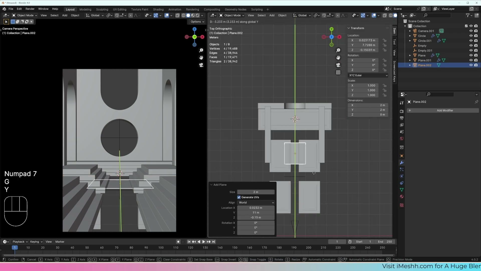
Scale the plane up until it stretches past every element you've built so far, then drop it down so it sits flush with the bottom of the arches. This is a simple placeholder floor. It gives every other element in the scene something to rest on while you carry on building the surroundings.
Modelling the water surface
Position a single plane just below the top of the staircases, and learn why water in Blender doesn't need thickness thanks to volume absorption in the shader.
Place the water plane below the steps
With the staircases sitting on the floor plane, it's time to add the water. You want the surface to sit just below the top step of each staircase so the stairs read as descending into a shallow pool rather than ending at the waterline.
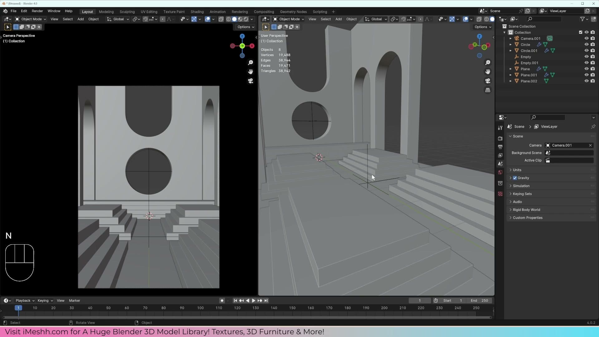
Place a single plane in the scene and raise it into position so it lines up a fraction under the top stair. That one flat plane is your entire water surface: no slab, no volume mesh, no thickness. If you've worked in other 3D apps where water is a thick block of geometry, this will feel wrong. It isn't, and the next sub-lesson explains why.
Why water doesn't need thickness: absorption
A flat plane with no thickness looks like it shouldn't work as water, but the shader does the heavy lifting. Blender's water material relies on an effect called absorption, and absorption is calculated from how far a light ray has to travel through the material. The geometry of the water mesh itself doesn't drive it.
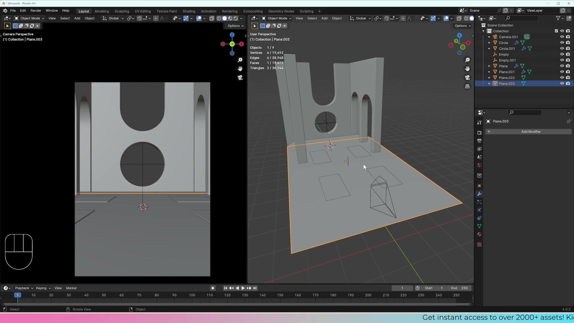
As light enters the water, photons get absorbed along the way. The deeper the ray travels before it hits something solid, the more light is absorbed and the darker the result. That's why a swimming pool looks brighter in the shallow end than the deep end: same water, different distances.
Because Cycles measures that distance by ray depth, anything you place below the water plane will appear darker the further it sits from the surface. A pebble a few centimetres under will look near its true colour; a tile a metre down will look noticeably dimmer. So as long as there's geometry underneath the plane for rays to travel toward, the absorption shader sells the illusion of real depth on its own.
Cut and inset the top of the staircases for grass
The flat tops of the side staircases aren't going to stay as bare stone. Later in the course they'll have grass growing out of them. To give that grass somewhere to sit, you want to carve a shallow recess into each top face rather than leaving it flush.
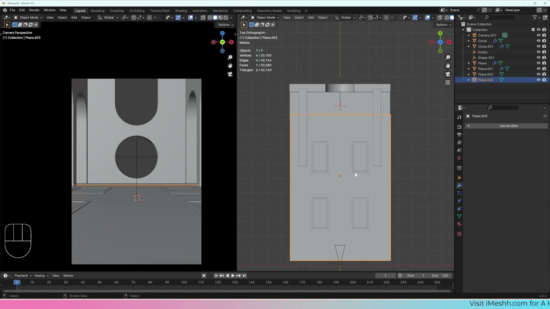
Drop into edit mode on the staircase and select the top face. Press I to inset, dragging inward until you've got a clean border around the edge. Then press E to extrude and pull the new inner face downward. That gives you the recessed pocket the grass will nest into.
Once the recess is cut, you'll want it positioned cleanly relative to the centre of the staircase. You can use Shift+S → Selection to Cursor to snap the inset geometry to a reference point you've already marked with the 3D cursor, then nudge the edge up to its final height by eye.
Cutting clean holes for the staircases
Mirror the water plane to halve the work, then use loop cuts and Delete Faces to carve precise openings where the steps pass through. Inset and extrude the rim so the water meets the geometry without a raw edge showing.
Loop cuts aligned with stair edges, then Delete Faces
With the staircases in place, you need to cut the water plane open around each one so the water stops cleanly at the stone instead of clipping through it. Mirroring the plane first halves the work: every cut you make on one side gets repeated on the other.
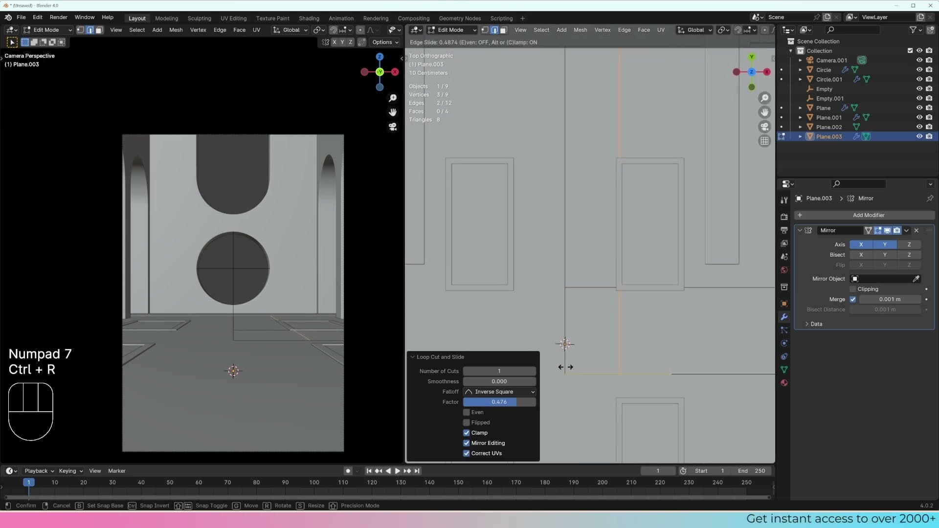
Set the water plane's origin to the 3D cursor (which is already snapped to the centre line) and add a Mirror modifier so the geometry is symmetrical across the join. Tab into edit mode and press Ctrl+R to drop loop cuts running along the inside walls of the first staircase (front, back and the inner edge) so the staircase footprint is enclosed by a clean rectangle of edges. The water should run right up to the edge of the stonework.
Switch to Face select mode by pressing 3, click the enclosed face, press X and choose Delete Faces. The hole opens immediately, and because the Mirror modifier is active the matching opening appears on the opposite staircase at the same time.
Inset and extrude the rim around each opening
With the openings cut, the bare edges sit flush against the staircase walls. I want a small recessed rim around each one so the water tucks under the stone rather than meeting it edge-to-edge. It hides the seam and stops that raw edge reading badly if the camera catches it.
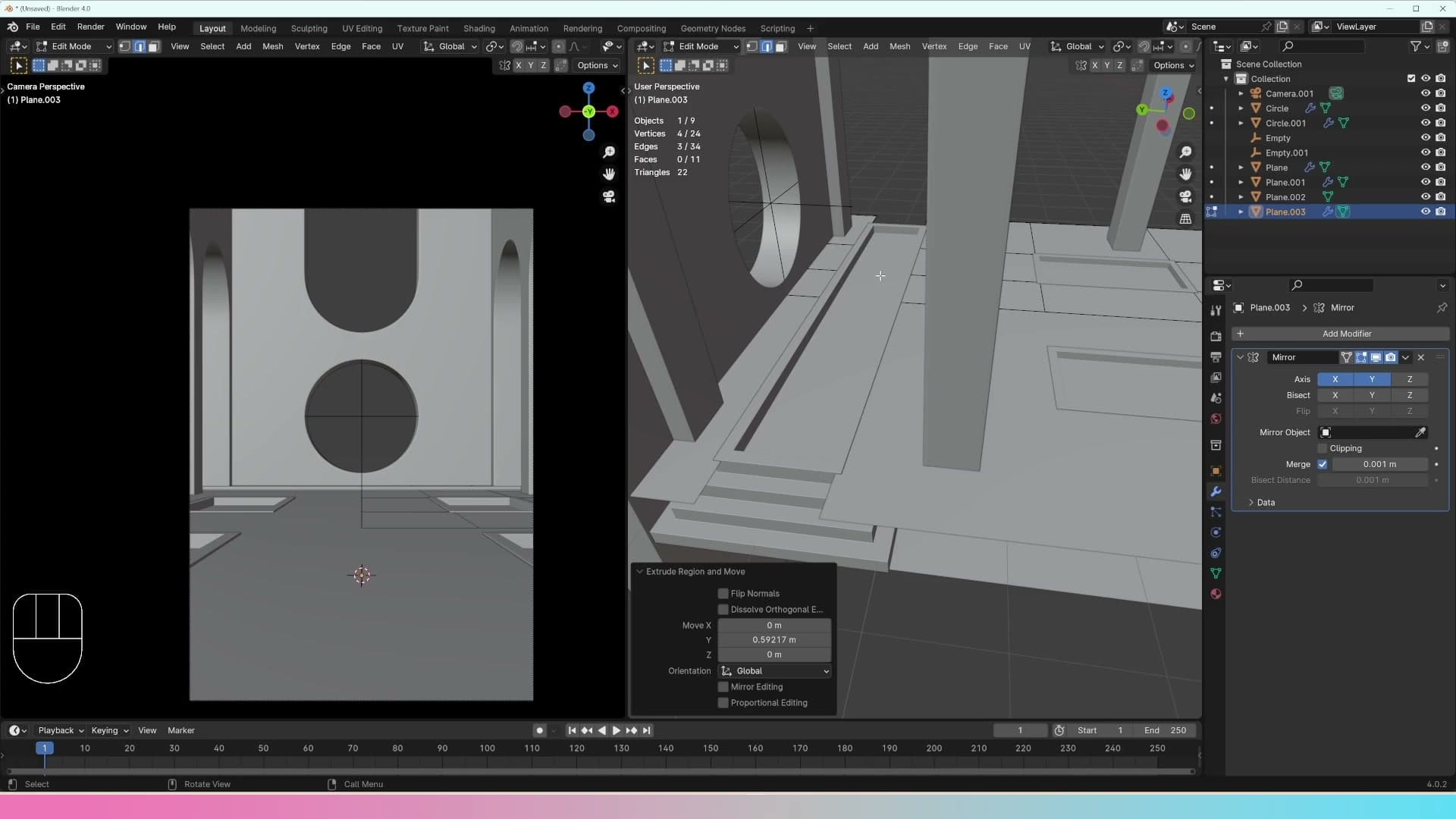
Stay in edit mode on the water plane and work through it in order: select the face around one of the openings and press I to inset it, then drag the new inset down so it drops slightly below the surrounding plane. With that inner edge still selected, press Shift+D to duplicate it and slide the copy along the Y axis into position. Then press E followed by Y to extrude the edge outwards along Y until it sits tucked under the staircase geometry.
The opening now has a clean, slightly sunken rim that disappears under the steps. Because the Mirror modifier is still doing its job, the second staircase gets the same treatment for free. The water plane reads as a continuous surface that the staircases rise out of, with no visible seam where they meet.
The pro habit: don't build what you won't see
A quick philosophy note on saving time. Off-camera geometry stays rough. Even big-budget VFX scenes are a mess once you step outside the frame. Build only what the render will actually show.
Behind-the-camera modelling is a waste of time
Pull the viewport back and the area just off-camera looks unfinished, almost empty in places. That's deliberate. If the camera is never going to see a chunk of geometry, professional 3D artists generally don't bother building it. Time spent on detail the render will never show is time taken away from the parts of the scene that actually sell the shot.
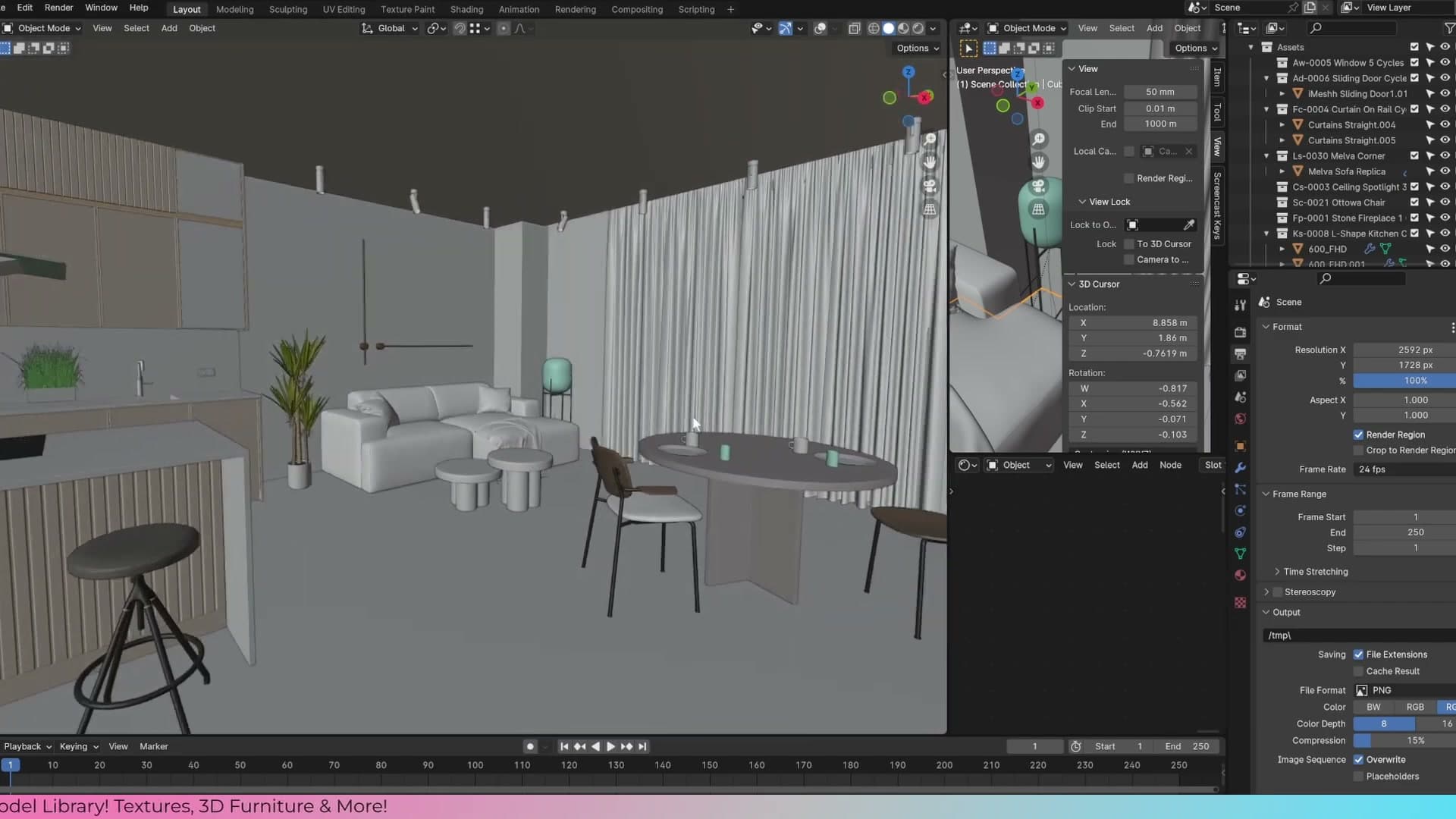
The same logic carries over into paid client work. If a customer asks you to render a room facing one direction, you don't have to dress the half of the room sitting behind the camera with furniture and props. You should still model the architectural shell properly (the walls, floor and ceiling that wrap around the camera) because the client might come back later and ask for a reverse-angle render. Walls cost very little to build; full set-dressing doesn't, so it can wait until the brief actually calls for it.
It isn't only a beginner shortcut, either. Watch a making-of breakdown for almost any big-budget film VFX scene and the space outside the framed shot is a complete mess. Even on huge productions, the rule holds: nobody wants to spend time on geometry the audience will never see.
Up next: lighting and materials
Everything the camera needs to see is now in the scene: the central arch, the mirrored side arches, the floor, the water plane and the surrounding walls. The geometry stage is done. In the next module you'll move on to materials and lighting, and then start layering in the props that turn this from a grey blockout into something that actually looks like a cathedral.
Tools and credits
Everything mentioned in this tutorial, with links.
- Blender the renderer this entire build runs in.
- iMeshh studio platform (project management, client review, asset library, invoicing). The asset library used in this tutorial is included with every iMeshh Pro plan.
- Poly Haven free CC0 textures and HDRIs.
Pillar guide: Beginner Course hub