Setting up the base cylinder
Delete the default scene, drop in a cylinder, scale it to real-world centimetres and apply scale and rotation before any mirror work begins.
Clearing the scene and adding the cylinder
Start from a completely empty scene. Press A to select every default object (the cube, light and camera), then press X and confirm to delete the lot.
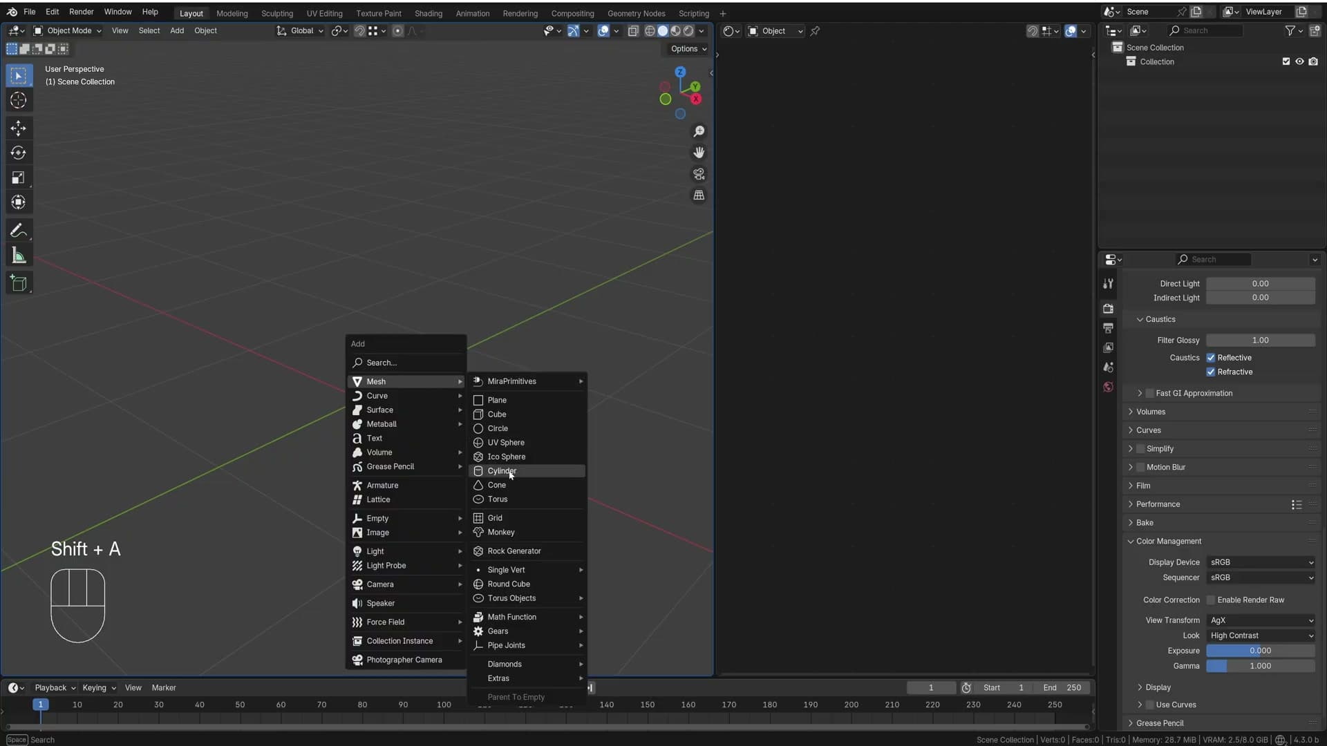
Add the first piece of geometry with Shift+A → Mesh → Cylinder. This single primitive is going to become one leg of the tripod base; the other three legs come from mirror modifiers later, so you only need to model this one.
Press N to open the sidebar and switch to the Item tab. You will be reading and typing values into the Location, Rotation, Scale and Dimensions fields constantly for the next few minutes, so it is worth leaving the panel open from the start.
Scaling the cylinder to 1cm by 30cm
Modelling at real-world dimensions keeps every later setting sane: bevel widths, wire thickness, render scale. The leg you are building is one centimetre thick and thirty centimetres tall, so scale the cylinder to match.
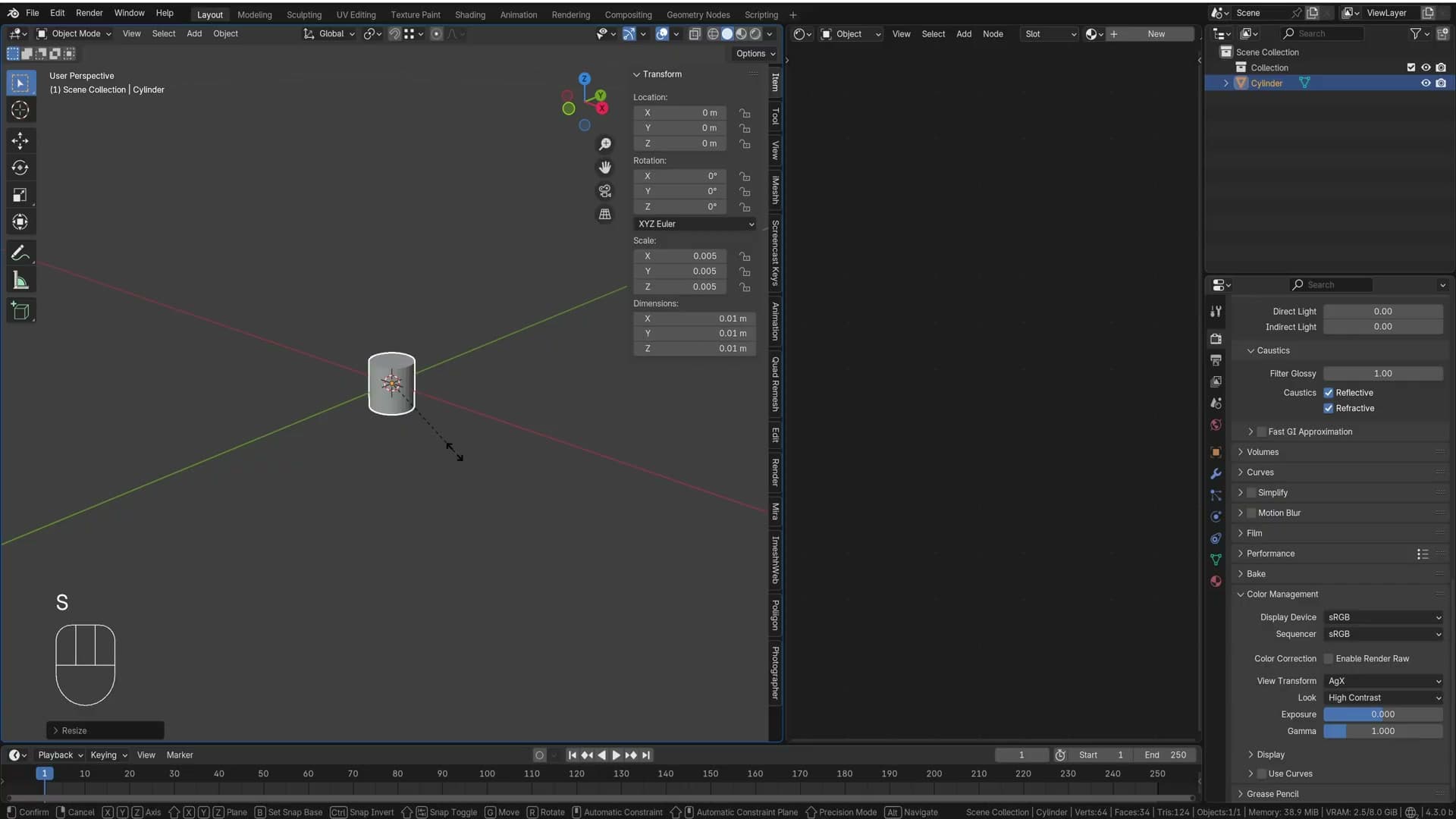
With the cylinder selected, press S to scale and type 0.01, then confirm. This squashes the cylinder down to one centimetre across on every axis. Press . (full stop) on the numpad to frame the now-tiny object back in the viewport.
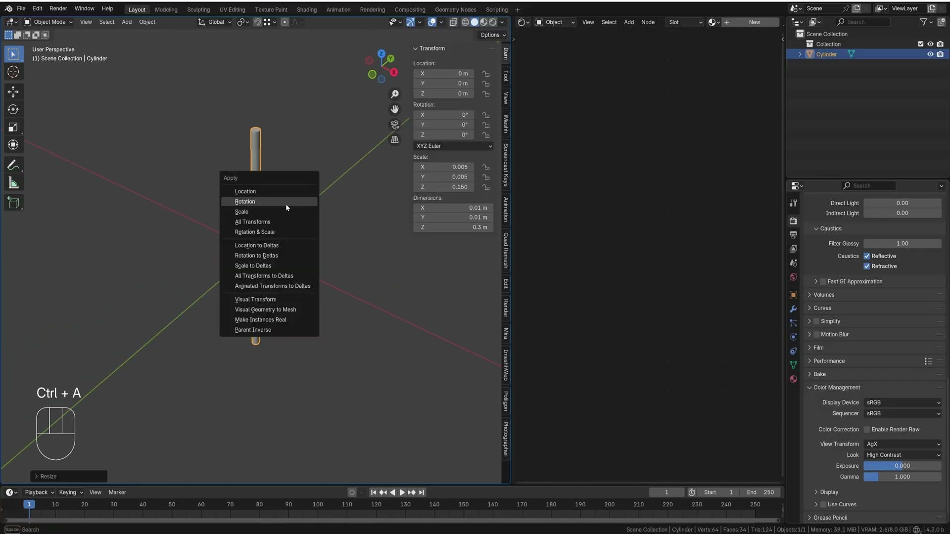
Now scale on the Z axis only so the leg gets its real height. Either press S → Z and type 0.3, or simply edit the Z field in the N-panel Scale row to 0.3. The Dimensions readout should now show roughly 1 cm × 1 cm × 30 cm.
Applying scale and rotation
Glance at the N-panel and you will see the Scale row still reads 0.01, 0.01, 0.3. The object is the right size visually, but Blender still thinks it has been scaled. Leaving those values in place causes downstream pain, particularly with the mirror modifiers in the next module which read the object's transform to work out where to place each flipped copy. Press Ctrl+A and choose Apply Scale. All three values reset to 1 and the object's true dimensions are baked into the geometry itself.
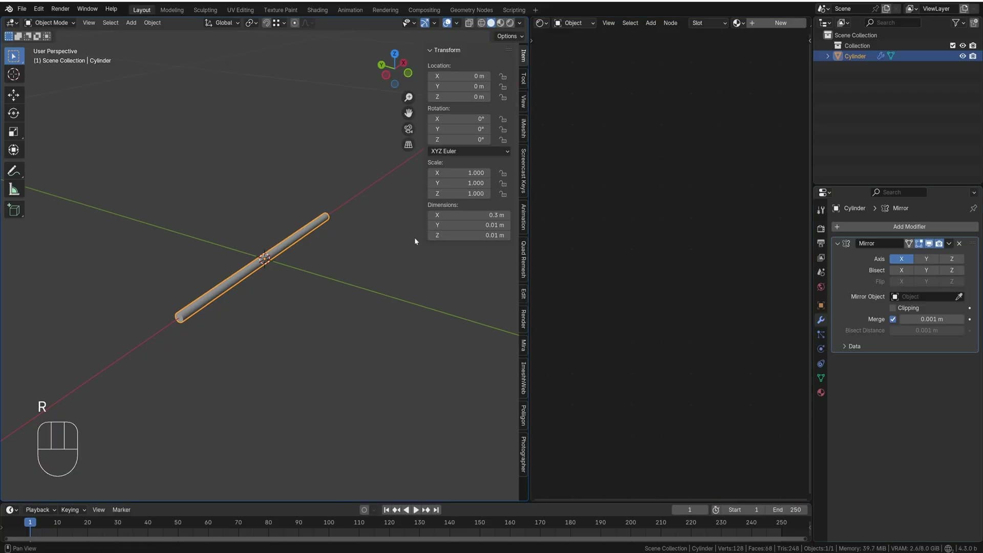
Next, rotate the cylinder so it lies on its side, ready to become a horizontal leg. Press 1 to switch to front view, then R, type 90 and press Enter. The cylinder tips over onto the X axis. Just like the scale, this leaves a stray 90° value sitting in the Rotation row, so press Ctrl+A a second time and pick Apply Rotation to clear it. The cylinder is now clean (scale of 1, rotation of 0) and any modifier you add from here will behave predictably.
Building the four-direction base with mirror modifiers
Stack three mirror modifiers, applying rotation between each, and use Bisect with a tiny threshold to carve the four-legged tripod from a single cylinder.
First mirror modifier with Bisect
With the first mirror modifier active, rotate the cylinder in edit mode so it tilts 45° off the world axis. Only one half is wanted, so tick Bisect on the mirror modifier. The geometry past the mirror plane is clipped, leaving a clean half-cylinder ready to be reflected.
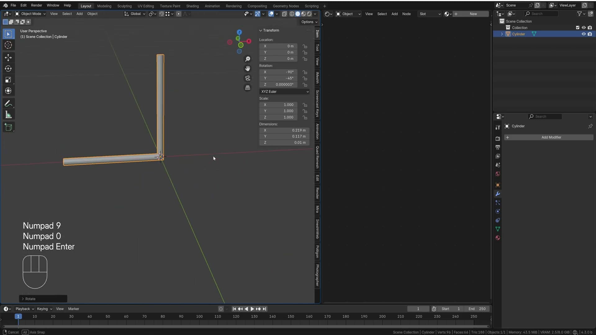
Drop out of edit mode and press Ctrl+A → Apply Rotation (or use the dropdown next to the transform values). Applying the rotation now is what stops the next mirror axis flipping sideways: every time you stack a fresh mirror modifier on top of an unapplied rotation, the new axis inherits the old one and the result drifts out of line.
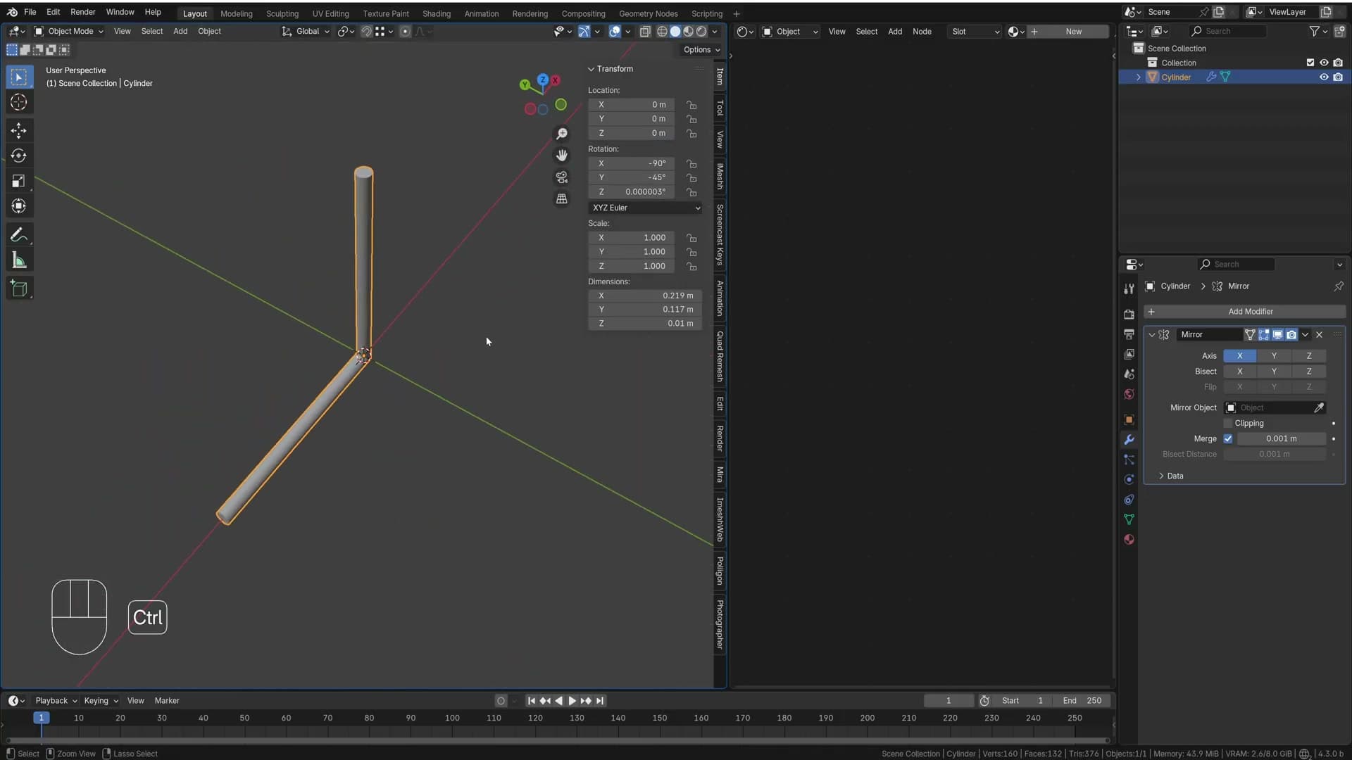
Back in edit mode, tilt the half-cylinder another 45° so it stands up as the start of the leg-and-stem shape. Numpad 3 drops you into the side view, then press R and rotate 90° to angle the cylinder upward. The lower portion will become a leg and the upper portion will become the stem of the lamp.
Second mirror with the 3D cursor pivot
Add a second mirror modifier from the modifier stack. Drop into edit mode from the top view and try to rotate the geometry. It behaves oddly because, once again, there's unapplied rotation on the object. Exit edit mode, press Ctrl+A and apply the rotation, and the mirror starts behaving sensibly.
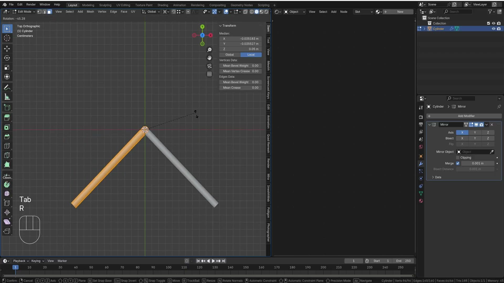
The second mirror needs to pivot around the world origin, not around the object's median point. Make sure the 3D cursor is sitting on the origin. If you haven't moved it, it should still be there; if you have, press Shift+C to recentre it, or use Shift+S → Cursor to Selected. Then change the Transform Pivot Point in the header to 3D Cursor.
Press numpad 7 for the top view, drop into edit mode, and rotate by -30°. The duplicate now sits at the correct angle, but Blender will show some extra slivers of geometry hanging off the mirror plane. Tick Bisect on the second mirror modifier to clip them. If the wrong half disappears, toggle Flip on that axis to swap which side the cut keeps.
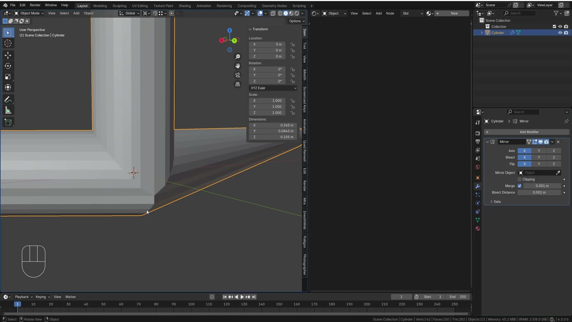
Because the cylinder is small, the default bisect distance of one millimetre is large enough to weld vertices that should stay separate, leaving strange artefacts at the join. Click into the Bisect Distance field, add an extra zero in front to shrink it, and press Enter. The cylinder snaps back to the shape it should have.
Third mirror and the four-leg tripod
Apply the second mirror's rotation in the same way: hover over the viewport and press Ctrl+A → Apply Rotation. With the rotation baked in, rotate the whole object by -120° so one leg points in the direction the next mirror will fold around.
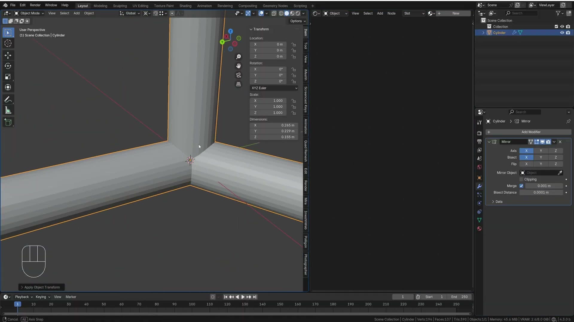
Add a third mirror modifier. Tab into edit mode and try a rotation: as you'd expect by now, the axis is slightly off because the previous rotation isn't applied yet. Exit edit mode, press Ctrl+A and apply, and the fourth leg snaps into place.
The same join issue reappears, so tick Bisect on this third mirror as well. If a vertex disappears that you wanted to keep, flip the bisect axis to bring it back. The result is a single cylinder driving four legs that radiate out in four directions, modelled by reflecting one quarter rather than building the other three.
This method isn't perfectly round. Stacking mirrors on a small cylinder skews the cross-section slightly. That's fine for now: the subdivision surface modifier added in the next module will smooth the geometry, and a couple of edge tweaks will tidy up the remaining flat spots.
Cleaning up the base with Loop Tools
Merge stacked vertices at the join, install Loop Tools and use Circle plus Space to even out the cylinder's profile after all the bisecting.
Dissolving stray verts and merging by distance
After the bisecting and mirror stack, the new top of the cylinder is a mess: stacked vertices from where the mirror axes overlapped, plus the odd stray point sitting outside the ring. Before reshaping anything, clear the leftovers.
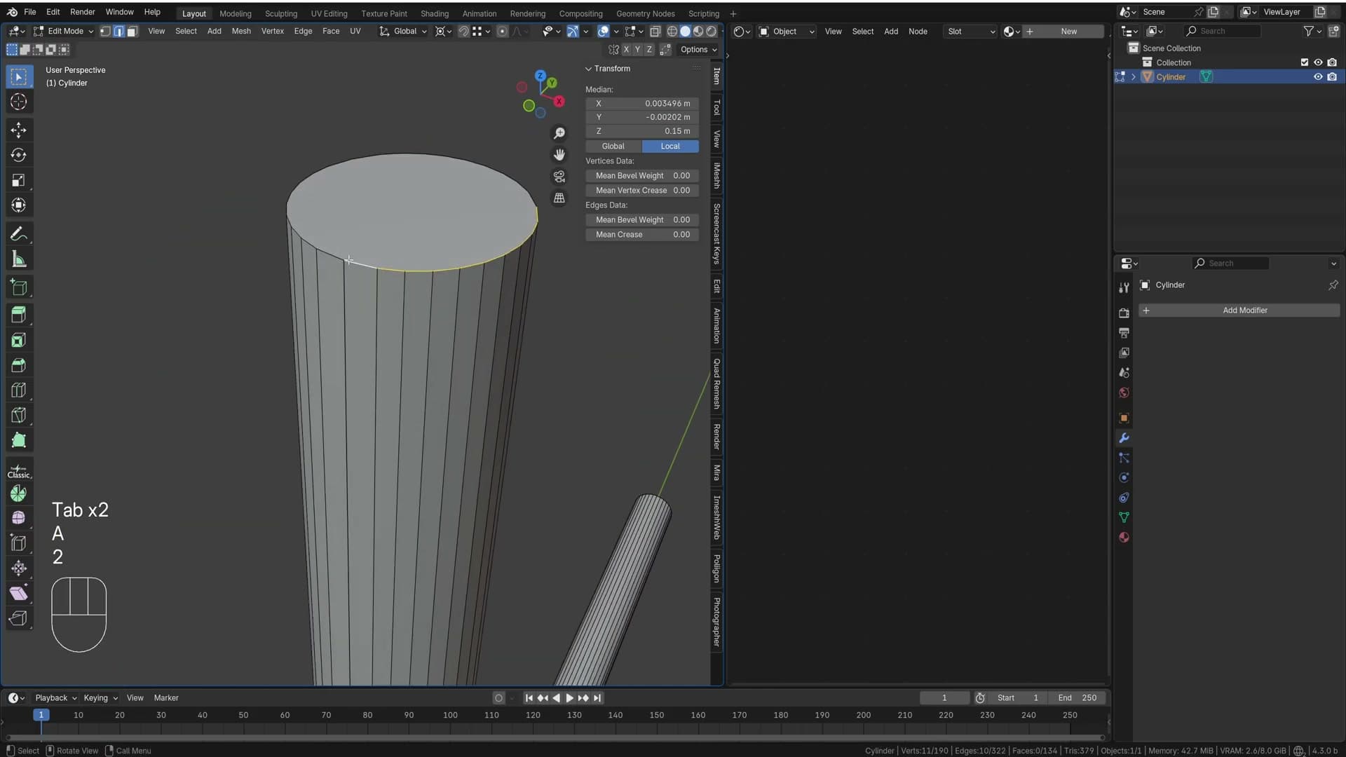
View the cylinder from above, press 1 for vertex select, click the stray vert sitting inside the loop and use X → Dissolve Vertices. The top now looks vaguely round, but Alt-clicking the top edge ring refuses to wrap the whole way around. That's a tell-tale sign that duplicate vertices are still splitting the loop in half.
Select everything with A, then open M → By Distance. The default threshold is too tight, so nudge it up to around 0.0005 and watch the header report how many vertices were removed. Three duplicates dissolve in this case, and Alt-click now grabs the entire top ring in one click.
Installing Loop Tools and circling the top loop
The top loop reads as round but the spacing between its vertices is still uneven. Loop Tools is the fix. It ships inside Blender but is off by default, so enable it first.
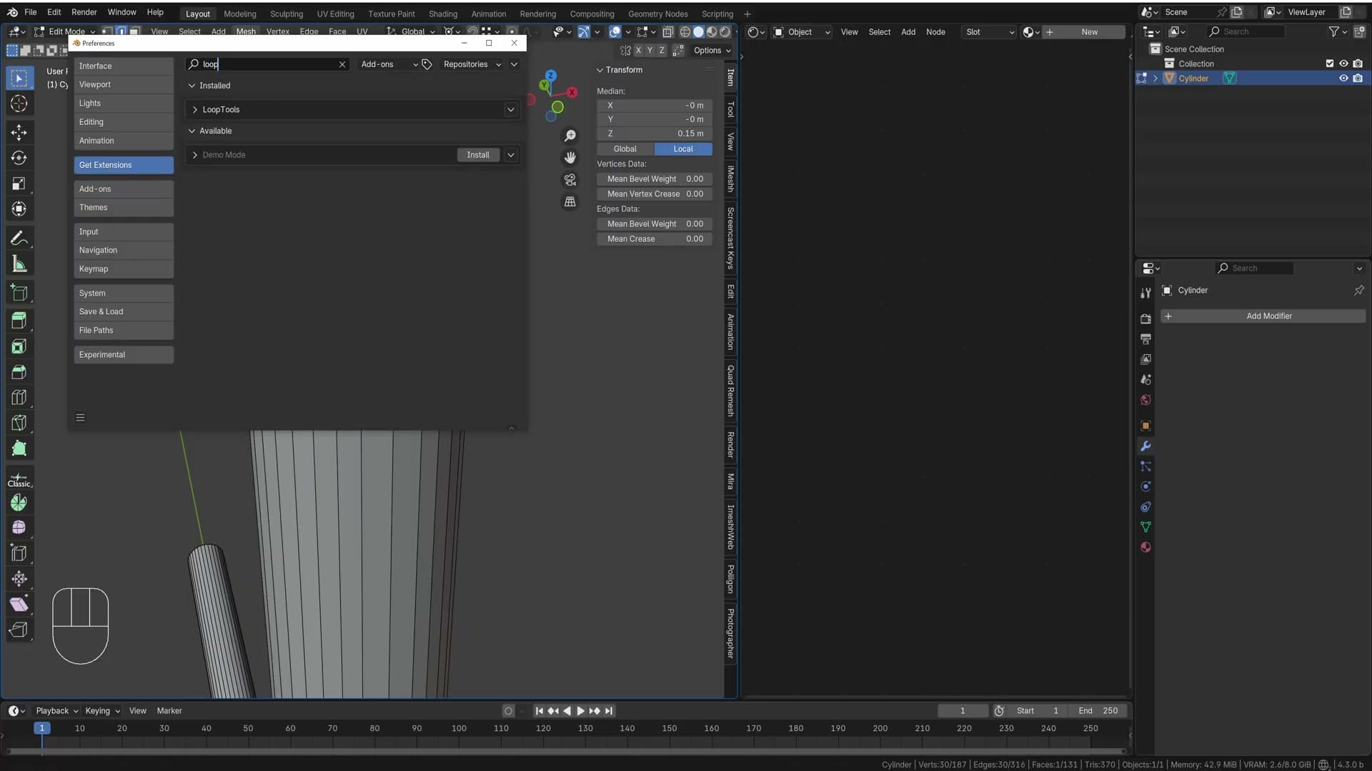
Go to Edit → Preferences → Add-ons (the same panel is labelled Get Extensions in Blender 4.x), search for Loop Tools, tick Install and close preferences. The Edit menu in the 3D viewport now has a new Loop Tools submenu.
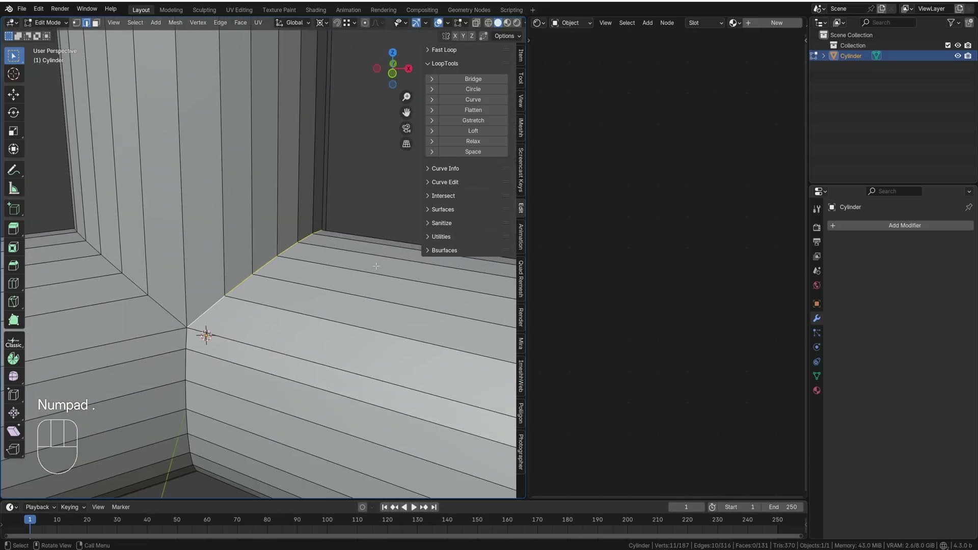
Alt-click the top edge ring to select it, then run Edit → Loop Tools → Circle. Blender redistributes the vertices into a perfect circle in a single click. It isn't the most precise way to build this kind of shape, but it's a fast, non-destructive way to tidy any ring that should be round.
Evening edges with Space and Shift+R
Drop down to the bottom of the cylinder and look at the rings stacked below the corner curve. They get visibly shorter and shorter as you descend, even though every loop wraps the same circle and should sit at the same edge length.
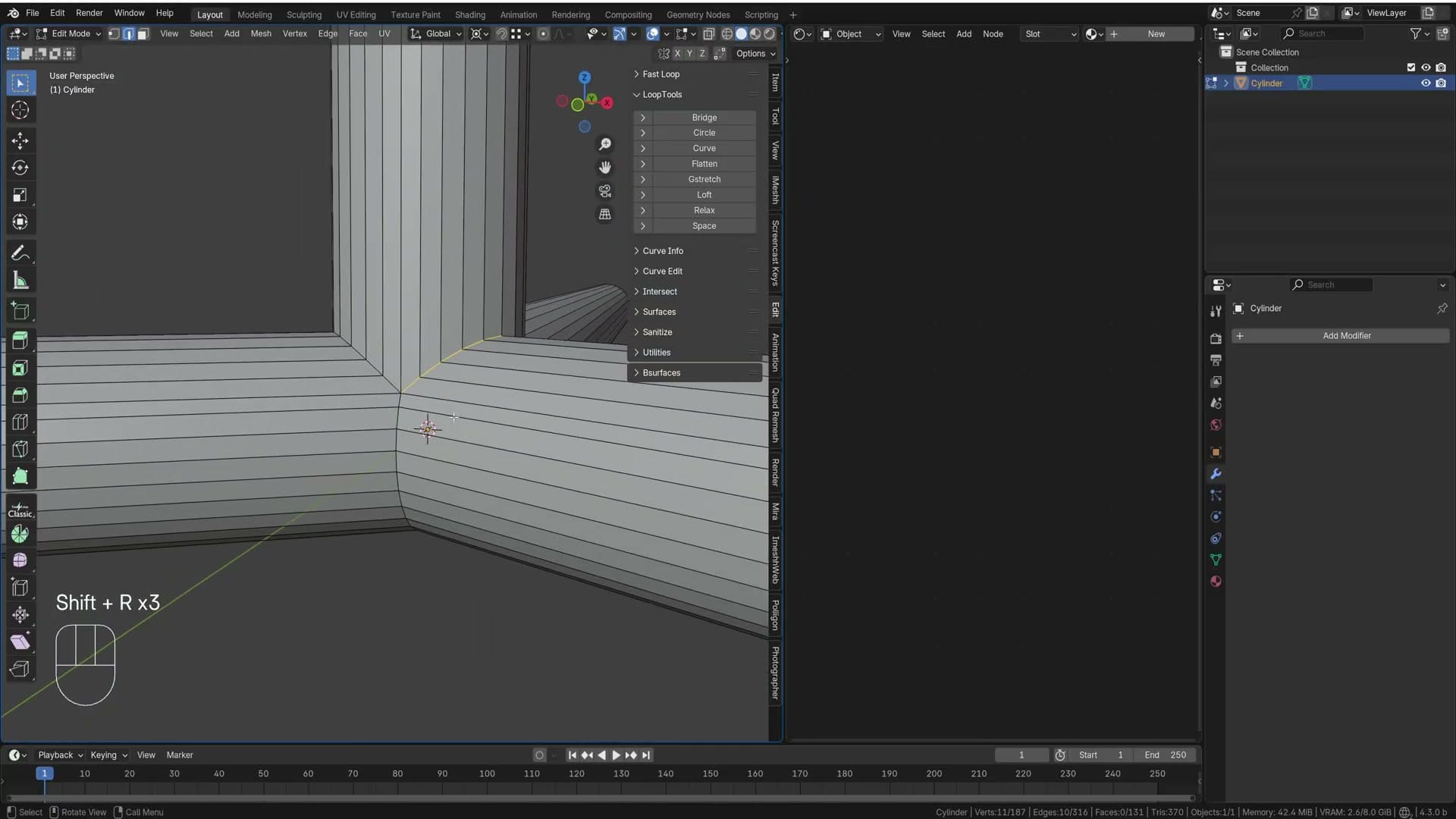
Alt-click a ring to select the full loop, then run Loop Tools → Space. Blender redistributes the loop's edges so every segment is the same length. Move up to the next ring, press Shift+R, and Blender repeats the last action. No need to dig through the menu again. Walk loop by loop down the cylinder until each ring evens out.
A handful of loops near the tight corners can't be evenly spaced without breaking the topology, so skip those rather than forcing them. The end result is a noticeably cleaner profile that's ready for the next stage of detailing.
Non-destructive bevels with weight
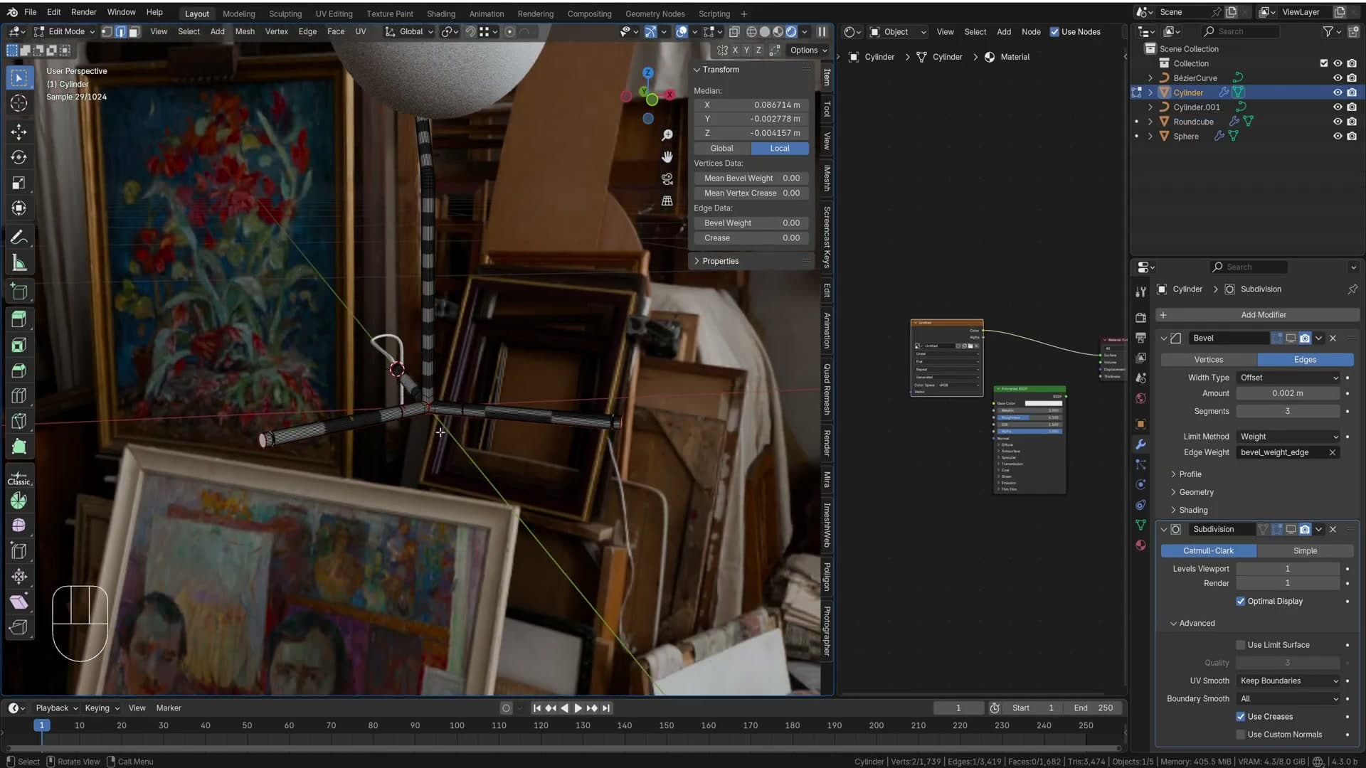
Skip Ctrl+B. Paint mean bevel weight on the corners, add a Bevel modifier set to Weight mode, then use Shift+G Similar by Face Angle to find matching edges.
Painting mean bevel weight on corners
Those sharp corners on the legs need softening. Nothing terminates in a knife edge in the real world, and the lamp wants a small bevel along every transition. Hold Alt+Shift and click the first corner edge, then keep Alt+Shift held and click the next one to add a second loop to the selection. Repeat until every corner edge ring you want bevelled is highlighted.
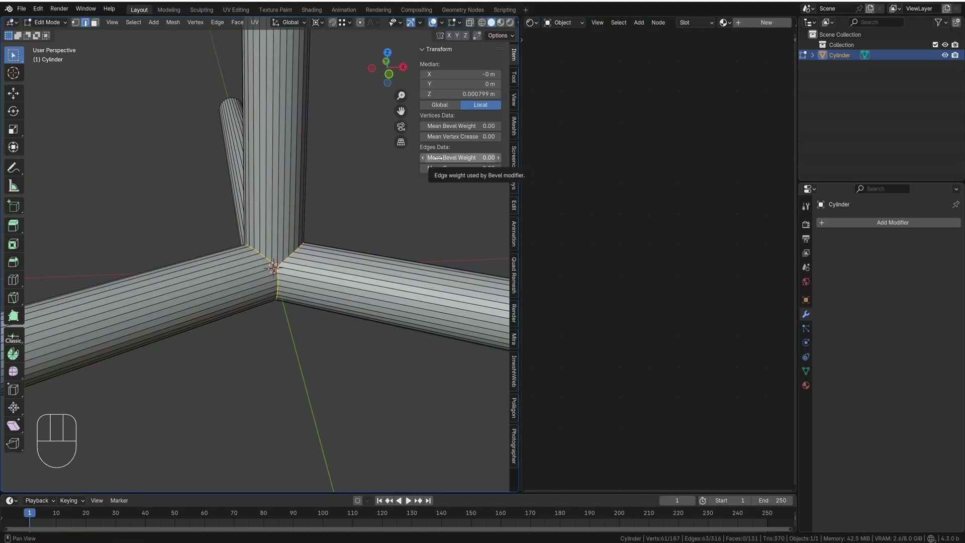
Ctrl+B with a couple of middle-mouse-wheel clicks would give you the bevel immediately, but the moment you apply it and move on to another step the geometry is baked in. You can't come back and adjust the radius six steps later. The non-destructive route is to mark the edges with a weight instead.
With the corner loops still selected, open the N-panel, switch to the Item tab and drag Mean Bevel Weight up to 1. The marked edges turn blue in the viewport, which is your visual cue that they carry a weight and will be picked up by a Bevel modifier in the next step.
Bevel modifier in Weight limit mode
Open the modifier properties and add a Bevel modifier. Out of the box it bevels every edge that sits below the 30° threshold, which is not what you want here. Change the Limit Method from Angle to Weight and the modifier only acts on the edges you just marked.
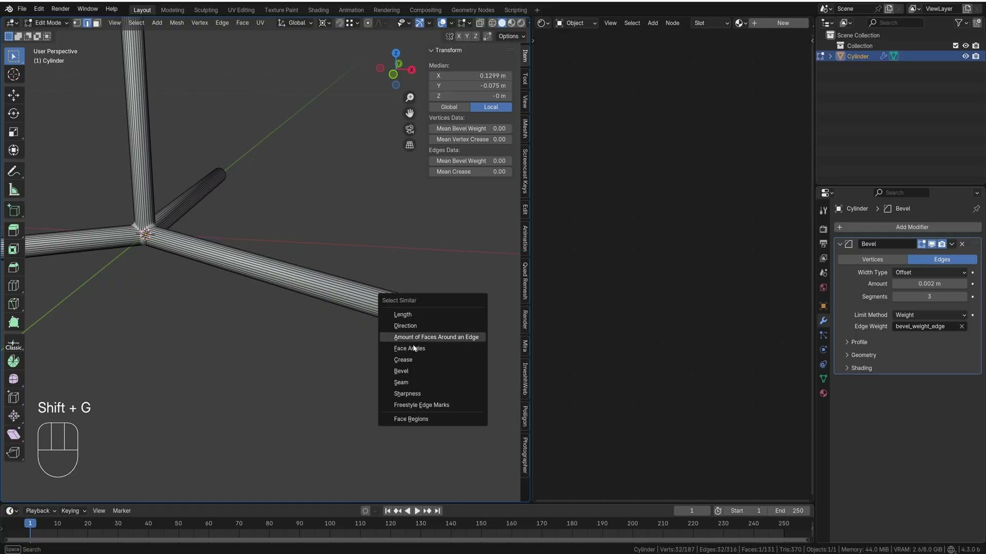
Drop the Width down to roughly 0.002 m. The corner loops should pick up a clean, narrow bevel while the rest of the cylinder stays untouched. Bump Segments up a notch or two until the curve reads smoothly at the angle you'll be rendering from.
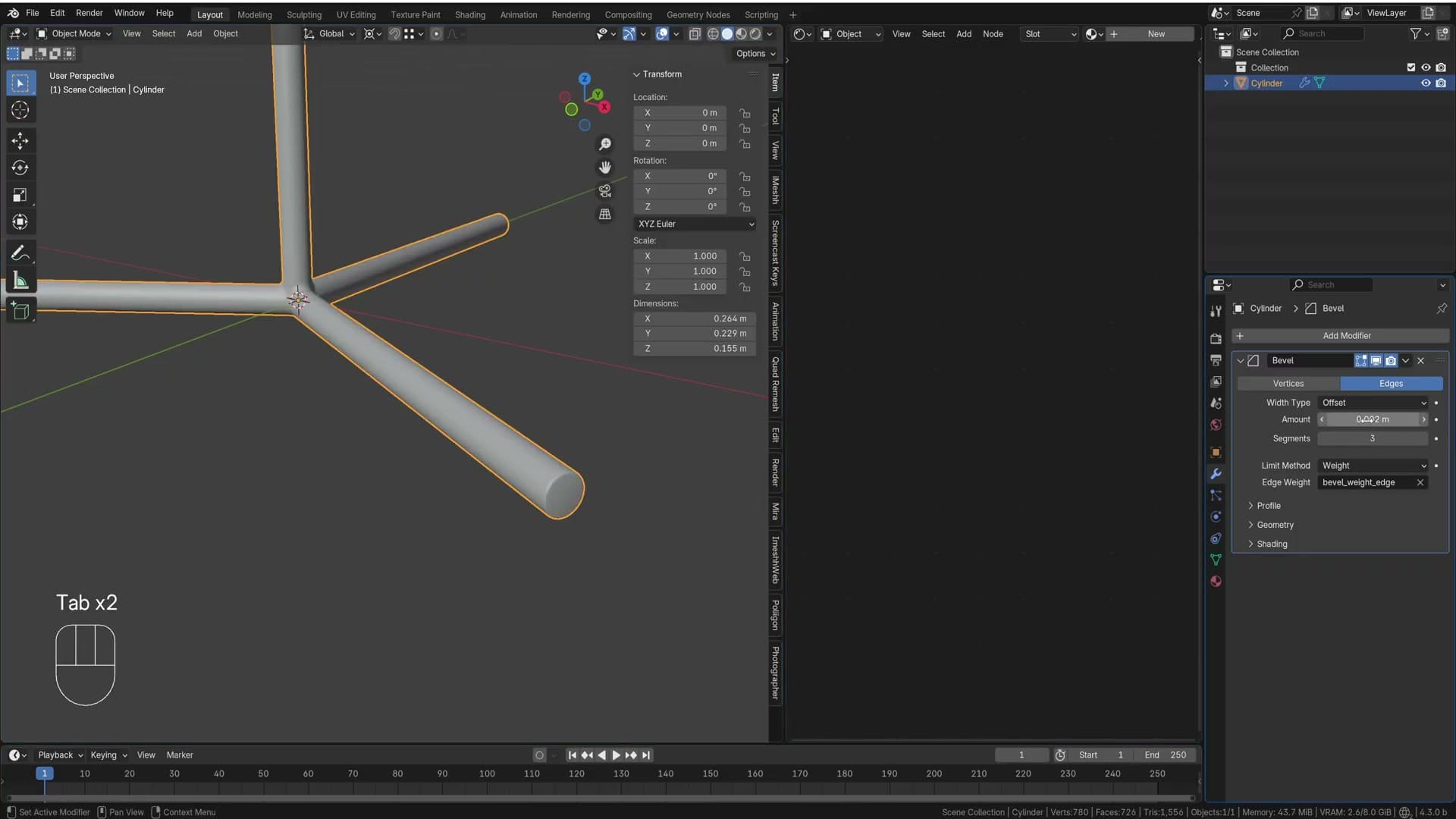
Right-click the object and pick Shade Smooth. The corners now round off gracefully, but the geometry underneath is still a plain cylinder with a couple of weighted edges. Change your mind about the radius later and you just tweak the modifier width. No re-modelling required.
Shift+G Similar by Face Angle for matching edges
The corner loops aren't the only edges that need softening. The upward-facing transition edges around the top of each leg also want a touch of bevel. Selecting them by hand on a four-leg mirrored object is tedious, so let Blender do it.
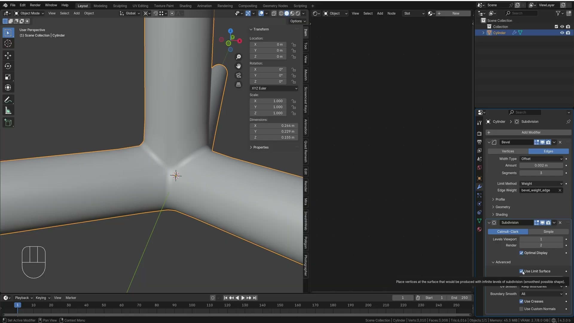
Click one of those transition edges to select it, then press Shift+G and choose Similar → Face Angle. Blender walks the mesh and selects every other edge sitting between faces at the same angle, which on a symmetrical lamp base means it bulk-picks every matching edge in one go. Give the selection a quick orbit to make sure nothing extra crept in.
Back in the N-panel, raise the Mean Bevel Weight on this new set, but only to about 0.3. The Bevel modifier multiplies the modifier Width by the per-edge weight, so with Width at 0.002 these edges effectively receive 30% of that, giving a subtler chamfer than the corner loops. Drop back into Solid view with Z if you need a clearer read, and you should see a soft highlight running along every transition without overpowering the main corner bevels.
Controlling subdivision with edge loops
Subdivision surface curves a pipe along its entire length. Ctrl+R support loops near each transition keep the cylinder straight where it should be straight.
Adding subdivision surface after the bevel
With the bevel sorted, drop a Subdivision Surface modifier onto the cylinder so it sits below Bevel in the stack: bevel first, then subdivide. Set the Render level to 1. That's enough to halve each edge and clean up the silhouette without piling on geometry the model doesn't really need.
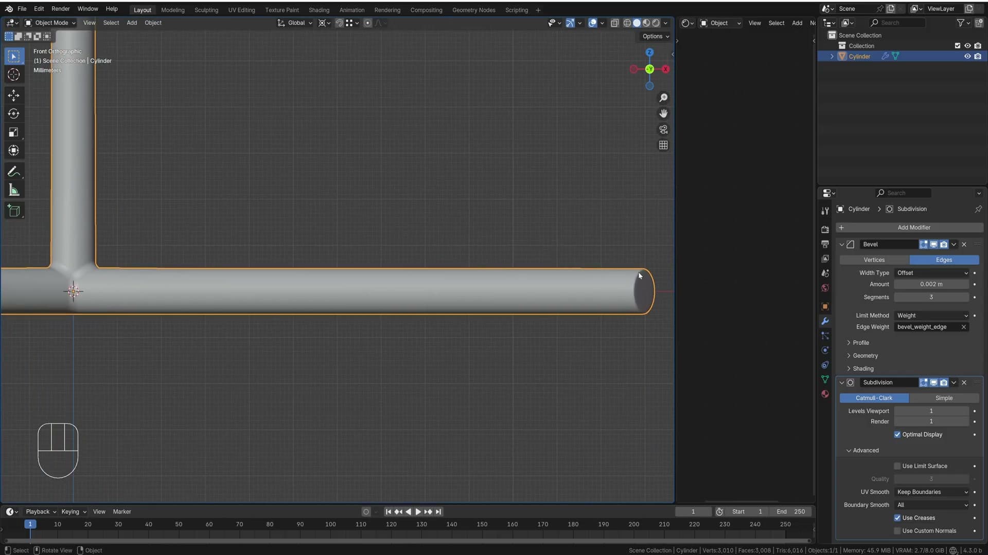
Toggle the modifier off and on once to see what it's doing. The edge count along the pipe roughly doubles each time, which is exactly what you want for a smoother curve at the bevels.
Switch to front view, though, and a problem shows up. Subdivision surface tries to even out every edge along the pipe, so what should be a perfectly straight section starts bowing gently higher and higher as it travels along its length. The pipe needs to stay straight all the way up to the join. Right now it isn't.
Support loops to keep the pipe straight
The fix is to give subsurf more geometry to anchor against. Tab into edit mode, press Ctrl+R, hover over the cylinder, and drop a loop near the transition where the bevel turns the corner. Click once to place it, then slide it in tight against the join before confirming.

Back in front view the difference is immediate: the edge tightens up and the pipe runs straight again right up to the join. Add a second Ctrl+R loop at the opposite end of the pipe where the geometry is starting to fall off, and slide that one in close too.
Eyeball the placement. It doesn't need to be perfectly measured, and a couple of support loops in roughly the right places is enough to turn a bowing pipe into a clean, smooth join.
Spinning the angled stem
Snap the 3D cursor to the centre of the top edge, then use the Spin tool at 30° to rotate a new section of geometry up into the angled stem.
Snapping the 3D cursor to the top edge
The last part of the main shape is the angled stem that comes off the top of the pole. The angle isn't arbitrary. I want it sitting in line with one of the legs so that when downward weight pushes on the stem, the load travels straight down through that leg rather than tipping the lamp sideways. That's how a real tripod lamp would be built.
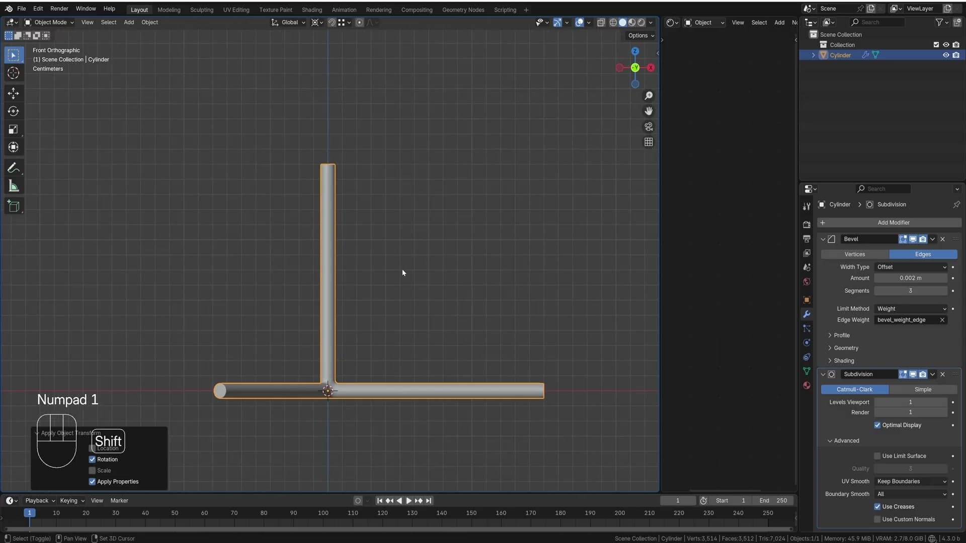
Press 7 for top view and rotate the top edge -30° so it points along one of the legs. Apply the rotation with Ctrl+A → Rotation so the Spin operator that follows behaves predictably. Then press 1 to drop into front view.
Tab into edit mode and press Z to switch to wireframe. You need to see through the cylinder to place the cursor exactly. Select the top edge of the pole, then snap the 3D cursor to it with Shift+S → Cursor to Selected. The cursor now sits at the centre of that top edge, which is the pivot point Spin will rotate around in the next step.
Spin tool at 30 degrees
With the top edge still selected and the 3D cursor in position, press F3, search for Spin and run it. In the operator panel at the bottom-left, set the angle to 30 degrees. The top edge sweeps around the cursor and starts forming the angled stem.
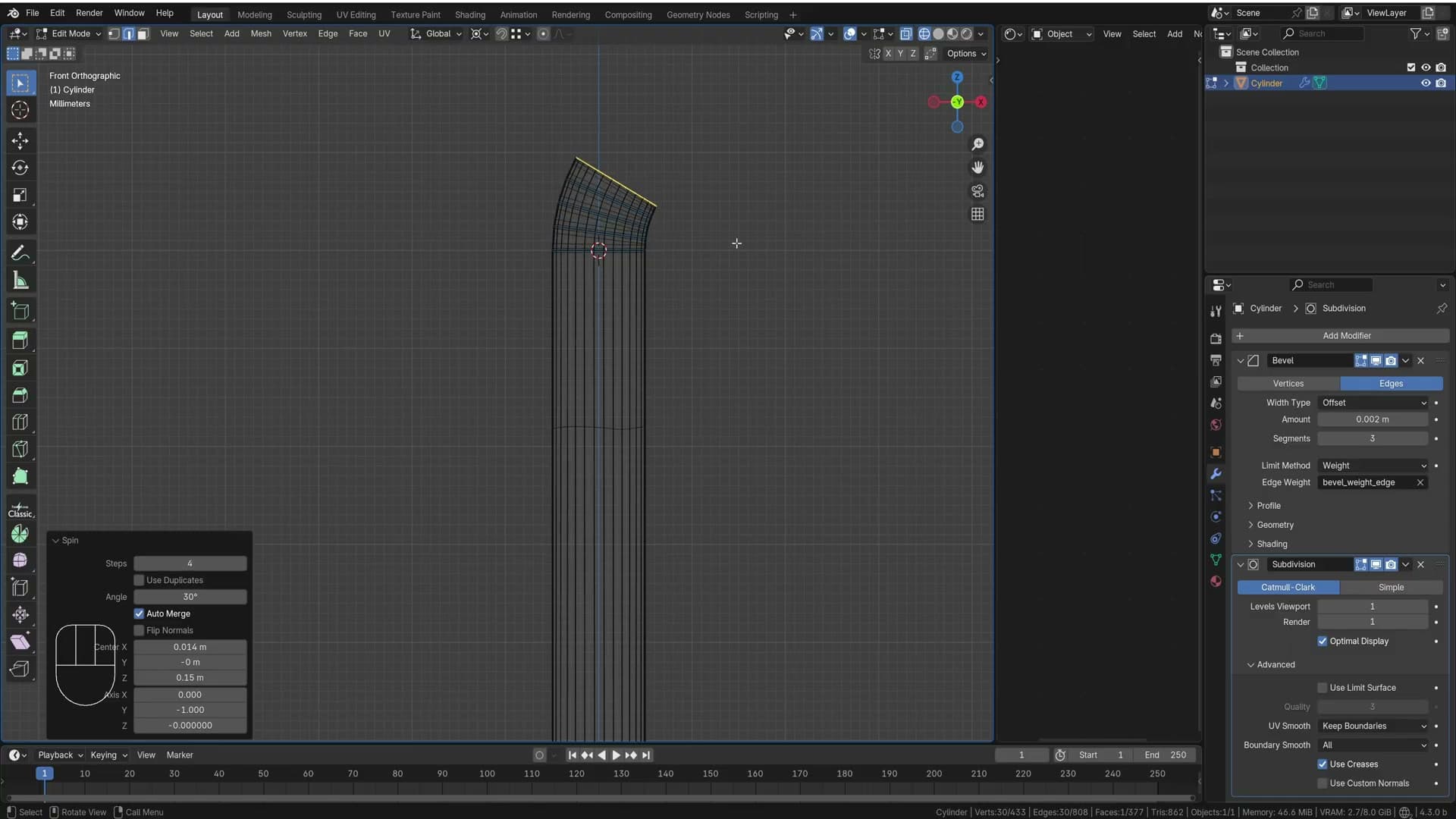
The default step count is too dense, so drag the Steps slider down. Hold Shift while dragging to scrub in smaller increments rather than jumping in big chunks. You want just enough geometry to form a smooth bend without packing the area with edge loops you'll have to deal with later.
Depending on whether you applied the earlier rotation, the Spin operator may default to the wrong axis and bend the geometry sideways instead of upwards. Cycle the X / Y / Z axis buttons in the operator panel until the sweep lifts the edge up and over in the direction you want.
Extruding the stem tip
With the new top edge of the spun section selected, press E to extrude it upwards into the rest of the stem. Pull it out to roughly the length you want the angled section to run, and lift it slightly taller than the original sketch. The bend eats into the visible height, so a bit of extra reach reads better in the final silhouette.
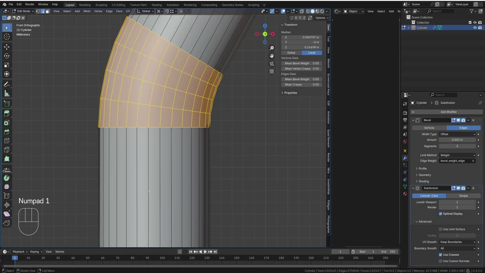
Tab back into object mode to check the shape. You'll notice the edges along the newly spun and extruded section are showing blue: they've inherited the mean bevel weight from the top edge you used as the seed for Spin. That's a problem, because the Bevel modifier (in Weight mode) will try to bevel them, and on a smooth pipe that adds geometry where you don't want it. Stay in wireframe and you can confirm there's currently no extra geometry, just the weight flag, but it will appear the moment subdivision surface and bevel resolve together.
Press Tab back into edit mode, select all the affected edges along the stem, open the N-panel and set the Mean Bevel Weight back to 0. The blue tint disappears and the stem is now a clean, weightless pipe again.
Clearing the weight introduces a second issue: the subdivision surface modifier will now try to smooth the whole pipe out, including the join where the stem meets the top of the vertical pole. A pipe should read as completely smooth right up to that join, then turn sharply. The fix is the same support-loop trick used on the rest of the model: Ctrl+R along the stem near the join and slide the new loop up close to the corner. The tighter you slide it, the sharper subsurf reads the transition.
Modelling the globe without UV sphere poles
A UV sphere with subsurf produces artefacts at its pole. The Extra Mesh Objects add-on ships a Rounded Cube primitive that subdivides into a perfect quad-only sphere.
Why the UV sphere fails here
With the pole bent into shape, it is time to drop the glass globe on top. Press 1 for the front view and click the top edge of the curved section so the globe ends up centred on the pole, not floating beside it. Press 2 first if you are not already in edge select mode.
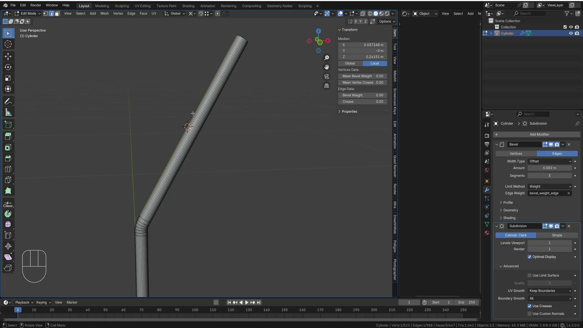
Snap the 3D cursor to that edge with Shift+S → Cursor to Selected, then tab out of edit mode so the next primitive lands at the cursor rather than inside the existing mesh.
The obvious move is Shift+A → Mesh → UV Sphere, then Ctrl+2 for subdivision surface and right-click → Shade Smooth. Do that and you immediately see why it does not work for a hero object: the top of the sphere puckers. Push the subdivision count higher and the artefact spreads further down the surface, not away.
The cause is the pole. A UV sphere converges every longitudinal edge to a single vertex at the top and bottom, and subdivision surface cannot smooth a fan of triangles into a clean curve. For a globe sitting directly under the camera, you need a sphere built entirely from quads with no pole.
Rounded Cube from Extra Mesh Objects
Delete the UV sphere and open Edit → Preferences → Add-ons. Type extra objects into the search and enable Add Mesh: Extra Objects. This ships with Blender but is off by default.
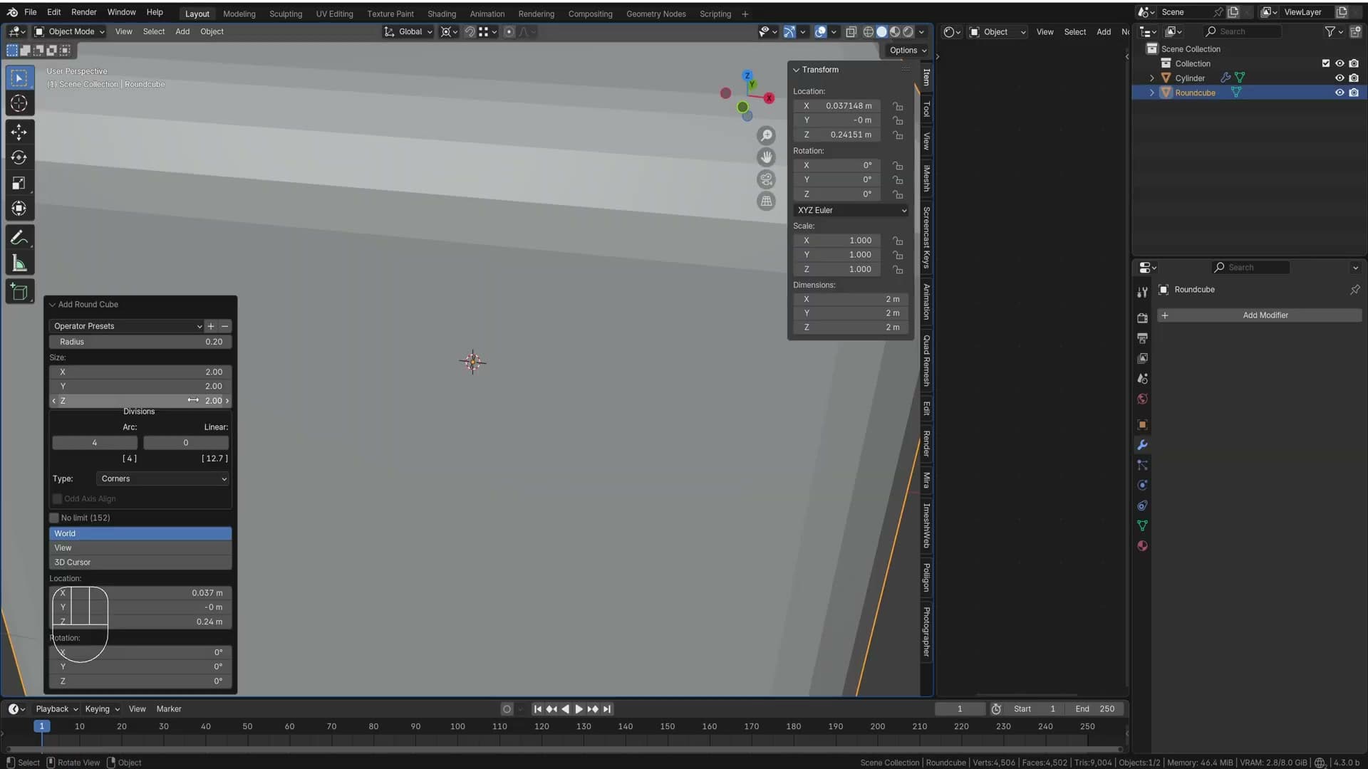
Back in the viewport, hit Shift+A → Mesh and you will now see a Rounded Cube entry. Add one, then in the operator panel at the bottom-left set Radius to 1 and bump the subdivision count to 8 to add more geometry.
What you get looks almost identical to a sphere from a distance, but inspect the topology and there are no poles. Every face is a quad and the curvature is uniform across the whole surface. That is what makes it survive subdivision surface without pinching.
Press 1 to return to the front view, tab into edit mode, switch to wireframe, and scale the rounded cube down to roughly bulb size. Use G to nudge it into position above the pole. Once it sits where you want it, Shift+S → Cursor to Selected again so the next piece (the connector ring) snaps to the same point.
Modelling the connector sphere
Wrap a UV sphere around the globe, paint-select the visible faces with C, delete the rest and extrude a pole through it. Bevel weights keep the join sharp under subsurf.
UV sphere wrapped around the globe
With the pole in place, start the connector by pressing Shift+A and adding a UV sphere. Scale it down until it just encloses the globe. You want the new sphere wrapping over the top of the existing geometry rather than floating outside it.
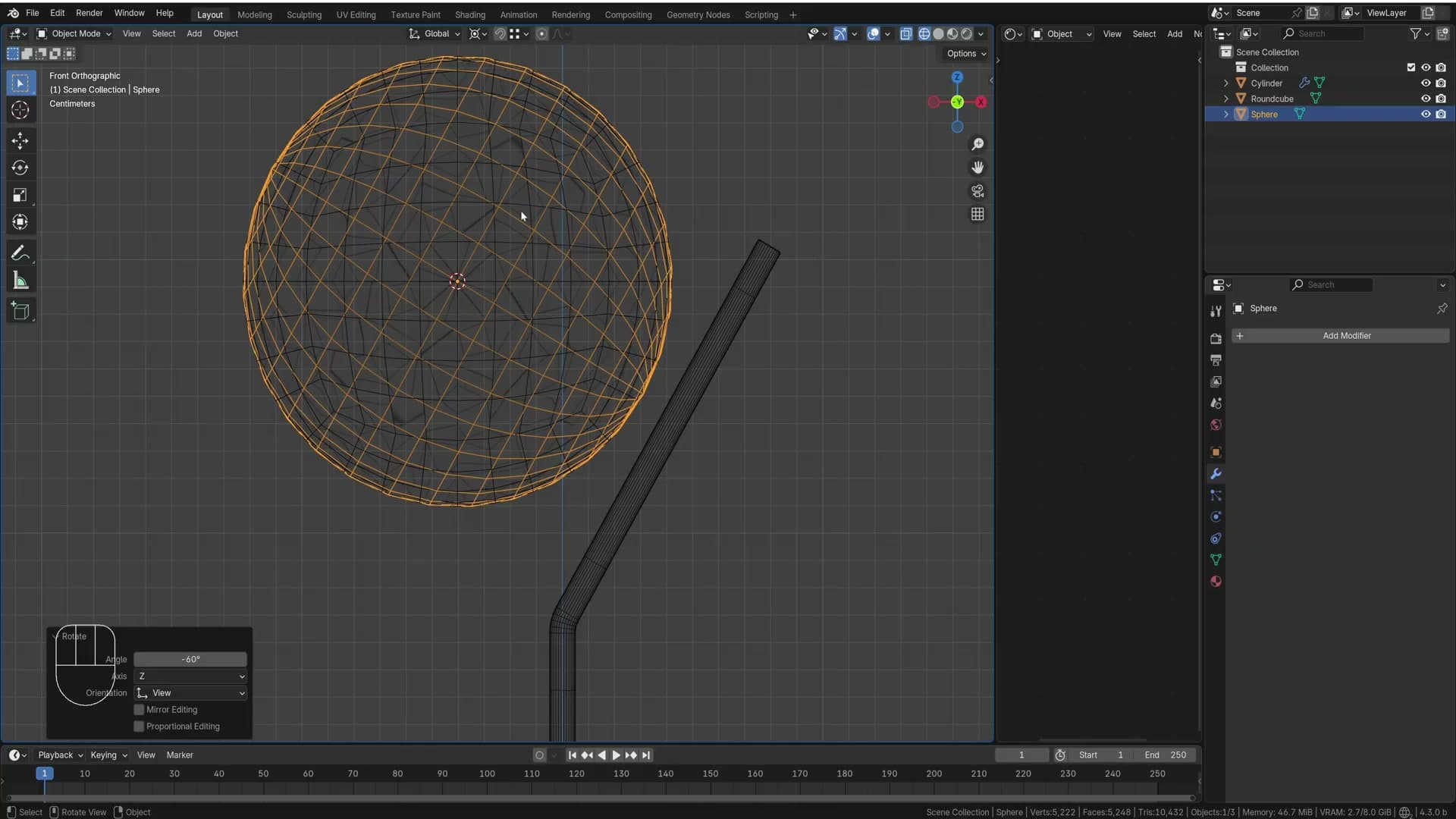
Because the two spheres now share almost identical surfaces, you'll see flickering artefacts where Blender can't decide which face sits in front. That sorts itself out as soon as you delete the faces you don't need, so ignore the noise for now.
Rotate the UV sphere by −60° on Y so its rings line up with the tilt of the spun pole. The value mirrors the 30° spin you applied earlier. What matters is that one ring of faces sits flush across the join before you go into edit mode.
Paint-selecting faces with C and deleting
Tab into edit mode and press 3 for face select. Hold Alt and click an edge to pick the ring of faces that runs around the sphere where the connector should sit. Hold Shift+Alt and click the next ring along to extend the selection.
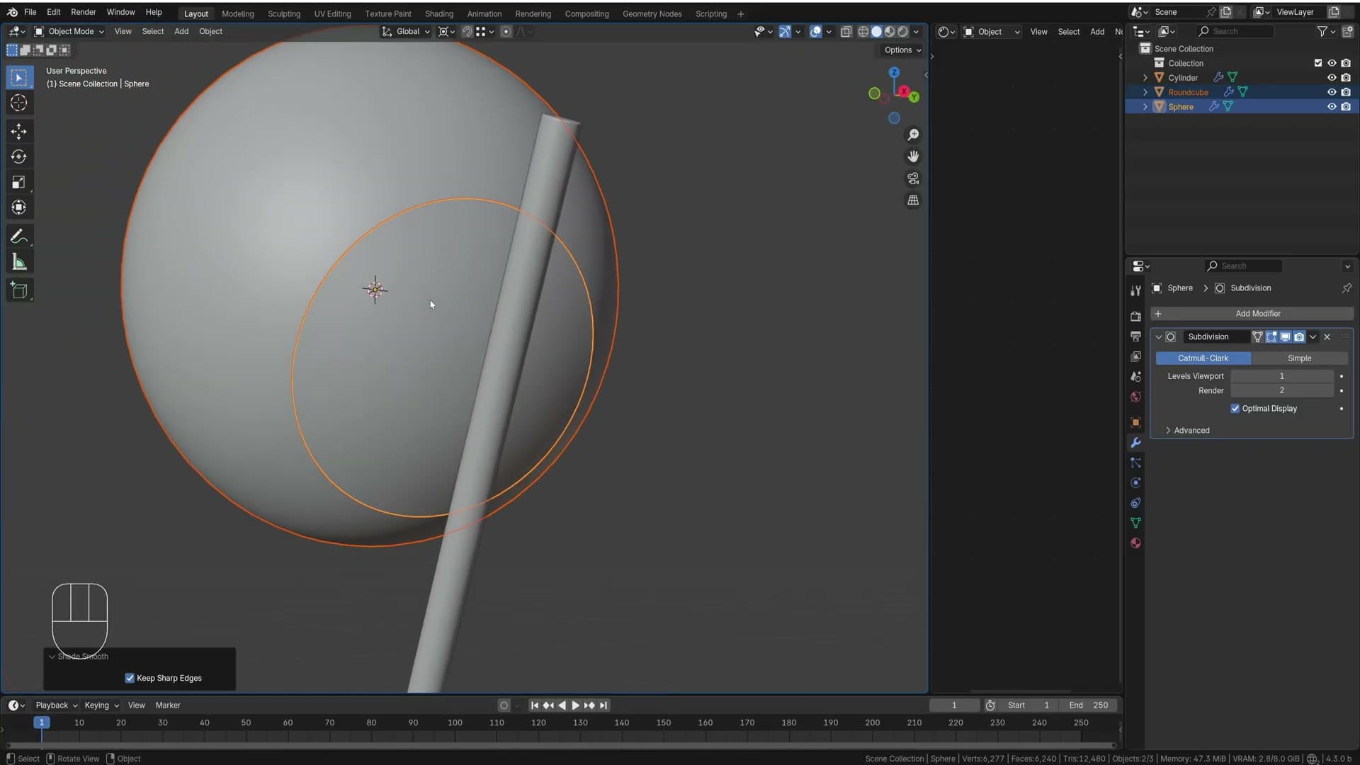
To grow the selection across the band of faces between those two rings, press C to activate the paintbrush selector and drag across the faces you want to add. It behaves like painting. Much faster than shift-clicking each face individually, especially over a curved surface.
With every face that belongs to the connector selected, press Ctrl+I to invert the selection and X → Faces to delete everything else. Only the connector ring is left wrapped around the globe.
Add a subdivision surface modifier to both the pole and the new ring with Ctrl+1, then right-click each and pick Shade Smooth. Nudge the ring down the pole until it sits roughly where the join should be. You'll refine the position once the rest of the geometry is in.
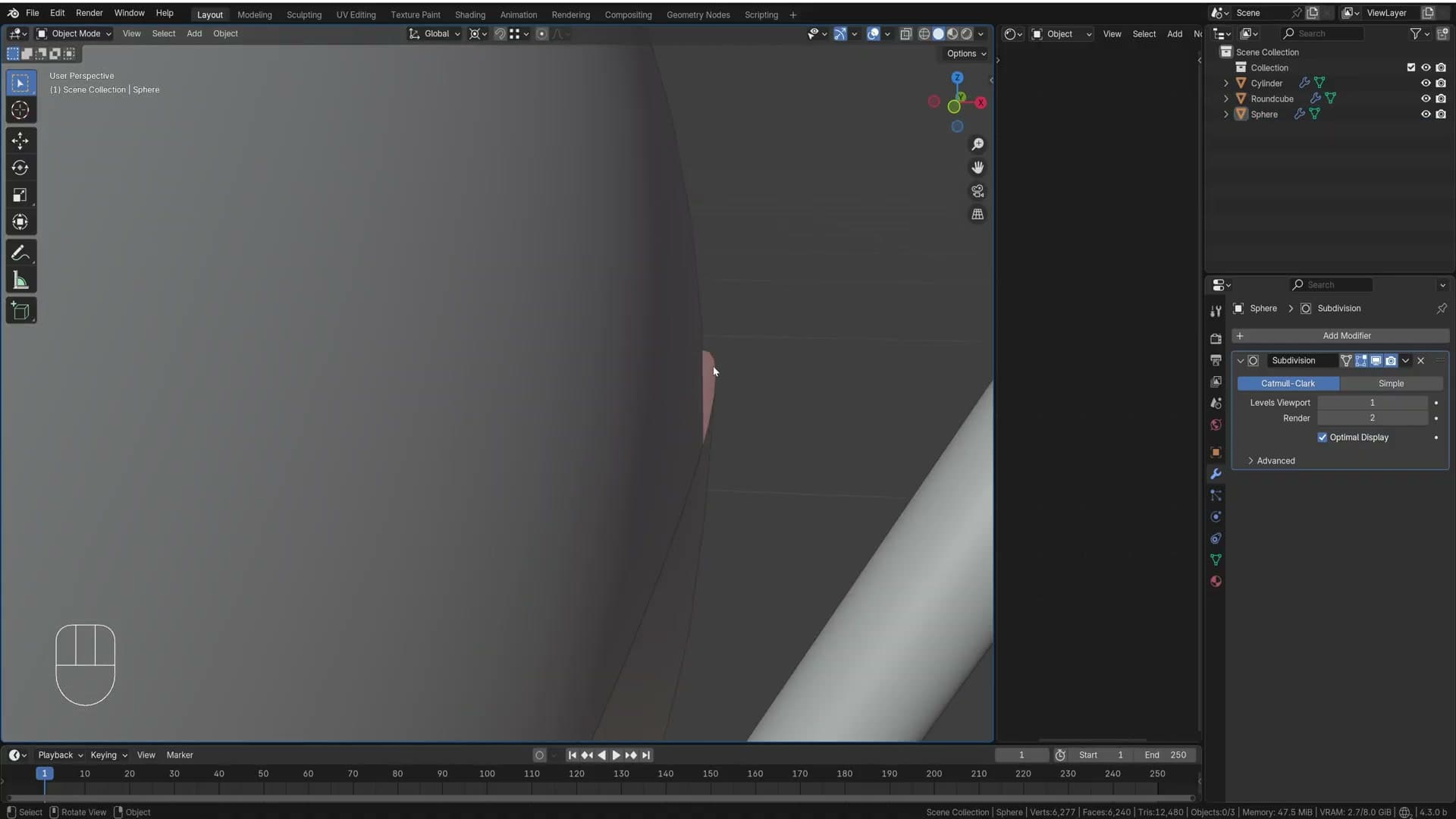
Extruding the pole through the sphere
The connector is currently a flat band with no thickness. In reality it would be a solid metal piece carrying the pole through, so you need to extrude that geometry now. Click the ring object and tab into edit mode.
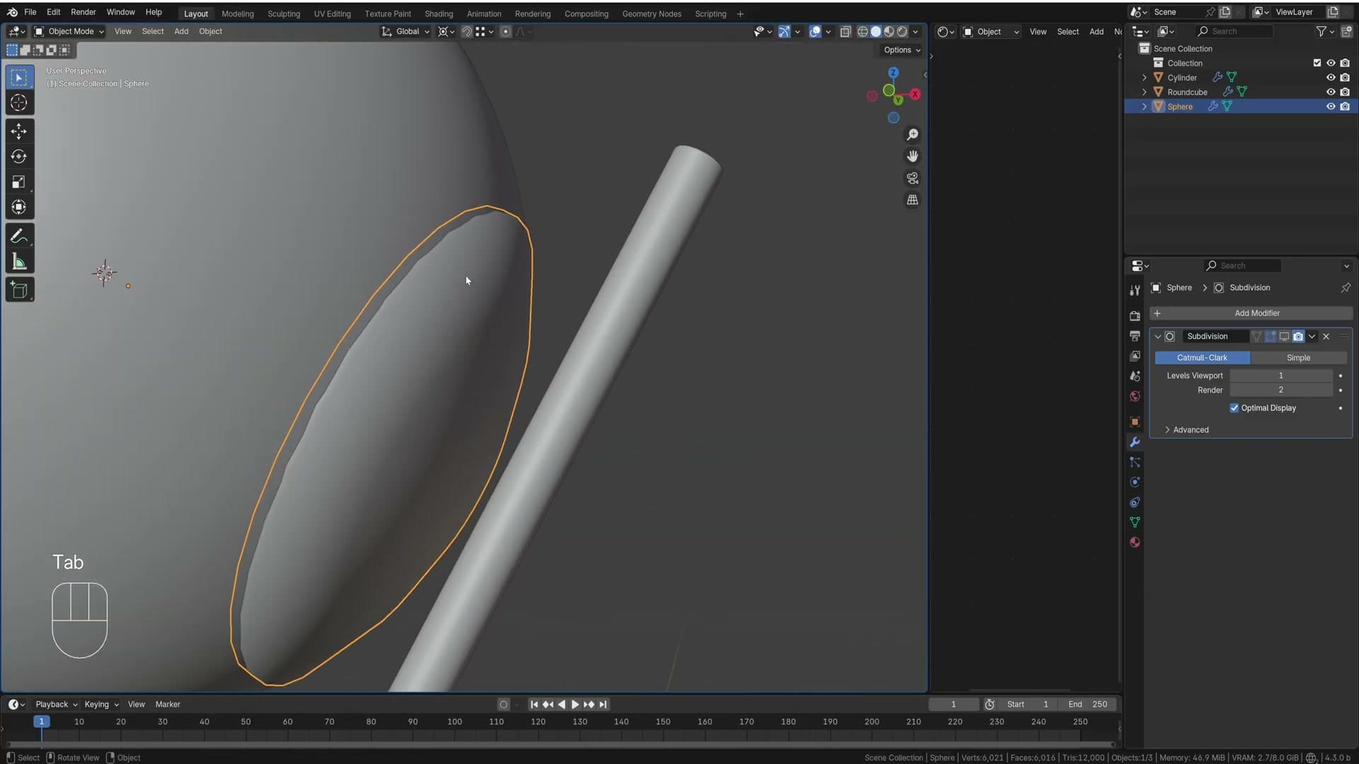
Press 2 for edge select, Alt-click the inner edge loop where the pole should emerge, then try pressing E to extrude. The extrusion drifts loose because there's no surface normal to constrain the direction, so the new geometry follows your mouse rather than the pipe axis. Undo with Shift+Ctrl+Z.
Instead, press F first to fill the loop with a single face. Now press E and the extrude snaps along that face's normal, sliding cleanly through the body of the connector. Once the new pipe pokes out the other side, press X → Faces to delete the cap that ended up inside. It sits inside the surrounding geometry and will never be visible.
Bevel weights on the join
With the through-pipe in place, you need to lock in the sharp edge where the new pipe meets the original connector ring. Add a Bevel modifier and switch Limit Method to Weight so it only acts on edges you explicitly tag in edit mode.
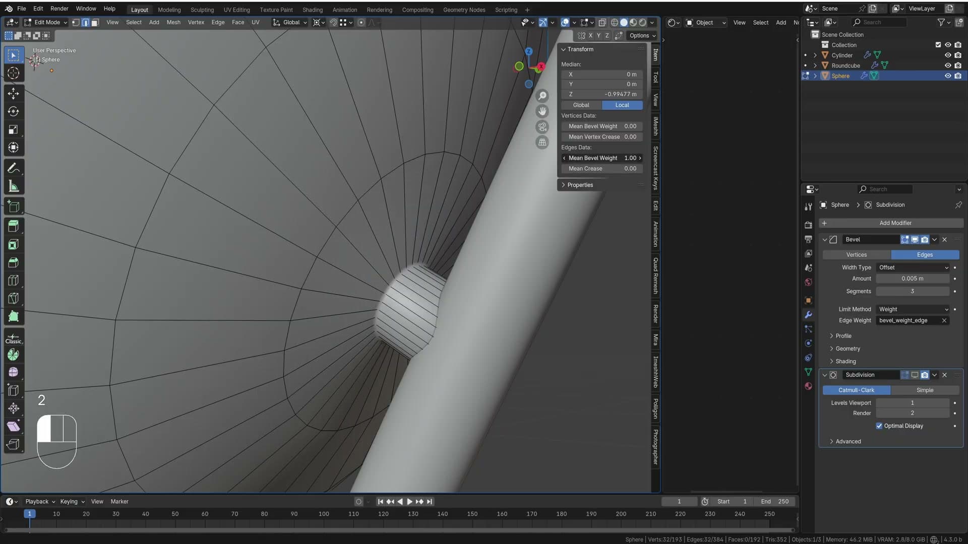
Tab in, press 2 for edge select and Alt-click the seam where the pipe joins the ring. Open the side panel with N, go to the Item tab and set Mean Bevel Weight to 1. Drop the modifier Width to roughly 0.005. Start at 0.001 and dial it up until the highlight along the join reads as a defined edge rather than a melt.
Drag the subdivision surface modifier below the bevel in the stack so the bevel runs first. The subsurf then rounds the small bevel face into a clean rolled edge instead of fighting against it, and the corner reads correctly from any angle.
Do the same on the other side, where the connector meets the main pole. Tab into that object, press 3, deselect with a click in empty space, press C and paint over the cap of faces where the pole enters. Press I to inset that selection, then E to extrude the inset face outward a touch. That gives you a lip the subsurf can hold onto.
Mark mean bevel weight on the new corner edges so subdivision doesn't smooth the lip flat. If a few stubborn artefacts linger around the join, press Ctrl+R and slot a couple of extra support loops close to each transition. The tighter the loop, the crisper the corner.
Adding base ring cuts and rubber feet
Use Ctrl+R plus G+X with the same offset on every leg for uniform cuts, then Alt+S with proportional editing in Sphere mode to push out spherical rubber feet.
Uniform loops with G+X offsets
With the sphere and the upper pole sorted, drop your attention to the bottom runner where the legs meet the ground. You want a single ring of geometry that sits at exactly the same distance from the end of every leg. Sliding loops by eye on four separate arms will never line up under a subdivision surface, so the trick is to add each cut numerically and rotate the whole object between cuts.
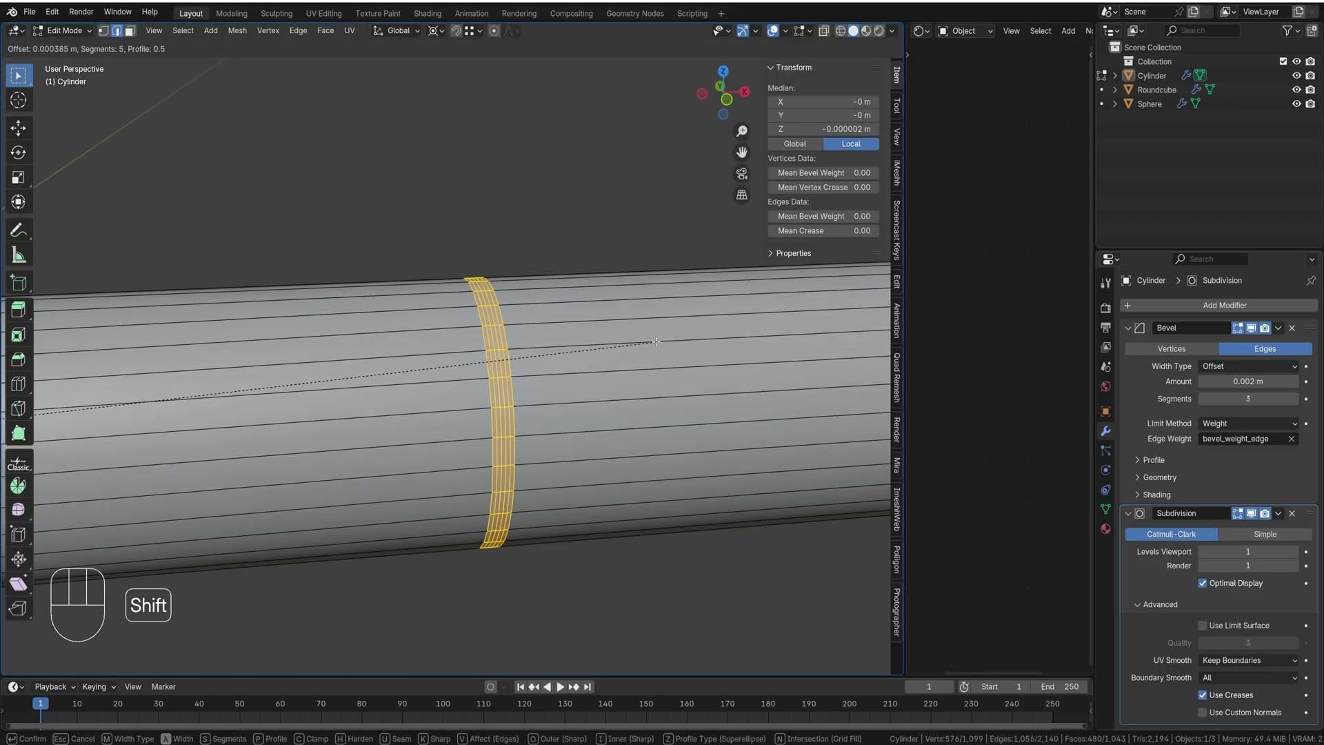
Hover over one leg and press Ctrl+R to drop in a loop cut, click to confirm, then press G+X and type -0.12 so the loop snaps to a known offset. Doing the same on the next leg with G+X won't work because the next leg points down a different axis. Instead, rotate the geometry so the next leg sits where the first one was.
Click the vertex at the centre of the base, press Shift+S → Cursor to Selected so the 3D cursor becomes your pivot origin, then select everything with A and change the pivot point to 3D Cursor. Now press R 120 to spin the entire mesh 120° around that point. The next leg is now sitting in the slot the first one was in, so Ctrl+R, click, G+X -0.12 places its loop at exactly the same distance.
Jump back to top view, A, R 120 again, and repeat Ctrl+R → G+X -0.12 on the third leg. You'll end up with a clean ring of cuts that all share the same width along each arm, ready to bevel as a single group.
Note: the upcoming GG slide step relies on these new loops being at identical distances. Because they were added numerically rather than eyeballed, you can use the same percentage offset later and trust it to land in the same place on every leg.
Bevel plus mean crease groove
Now turn those flat loops into a recessed groove that holds its shape under the subdivision surface. Hold Alt+Shift and click each of the new loops in turn so you have all of them selected across all four legs, then press Ctrl+B to start a bevel.
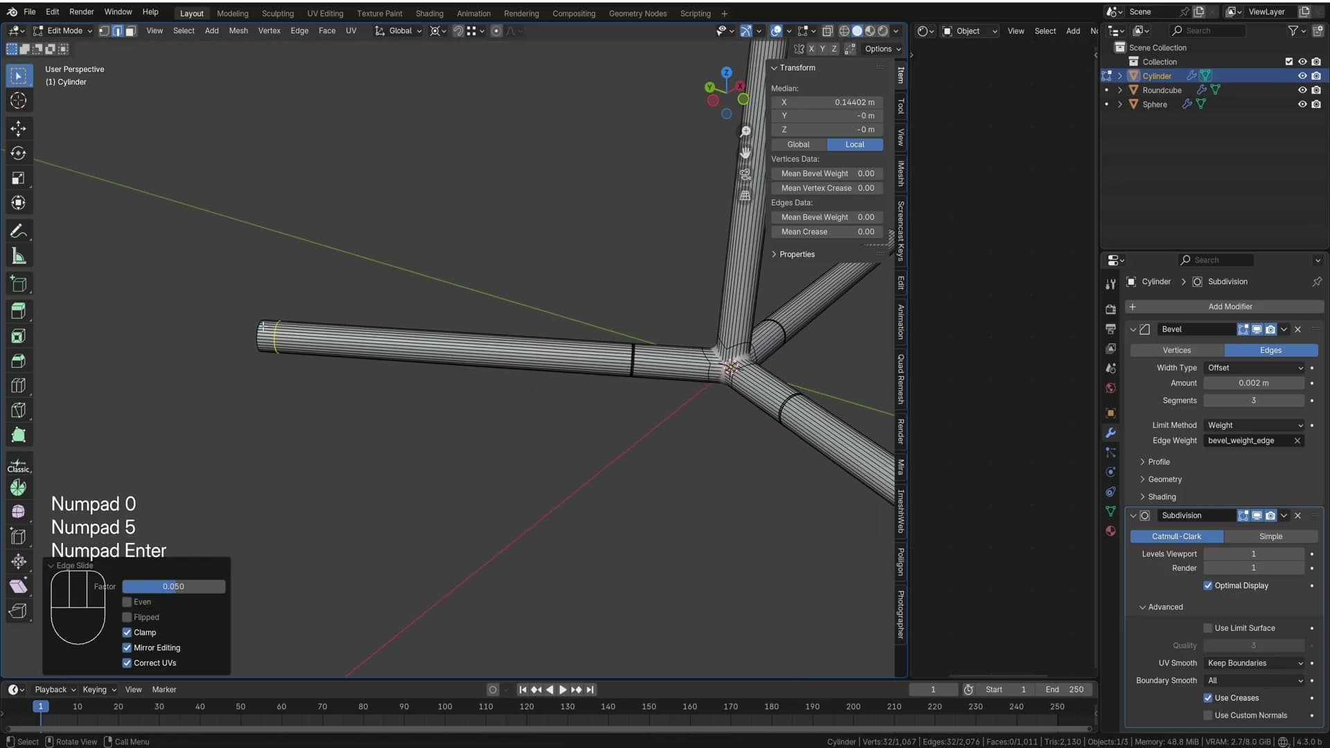
Roll the middle mouse wheel up while the bevel is live to add segments. One, two, three clicks gives you three segments, which is enough for what comes next. Confirm the bevel.
Press Ctrl+- on the numpad to shrink the selection back to just the inner edges, then press Alt+S to inset the bevelled strip into the surface. You'll notice the surrounding edges get dragged inwards too, which isn't what you want. Press Ctrl+- once more to tighten the selection further and run Alt+S again. With that extra loop sitting just outside the inset, the subdivision surface understands you don't want this section pulled in, and the groove stays crisp.
Finally, open the N-panel and slide Mean Crease up to 1 on the selected edges. The crease keeps the cut reading as a sharp groove under subsurf rather than softening into a dimple, and you should now see a clean ring detail running around every leg.
Proportional editing for spherical feet bumps
Next you want a couple of indents lower down where the rubber feet will sit. Click an edge loop near the foot of the first leg, then press G twice (GG) to slide along the existing edge and type 0.05. Do exactly the same on the matching loop further down, GG 0.05.
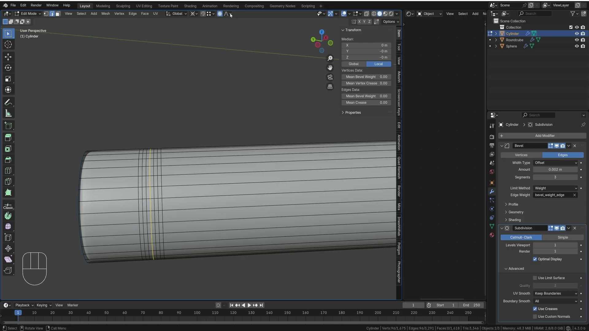
The reason to use GG here rather than G+X is consistency. GG slides along an edge as a percentage (1 is all the way to one end, -1 all the way to the other), so a typed value lands at the same proportional position on every leg. Because the earlier ring cuts were already placed at identical distances from the end, sliding 0.05 from each of them lands the new loops in matching spots without having to measure anything.
If you spot a stray edge created by the operation, click it and press X → Dissolve Edges to clean it up. Then select the new loops, Ctrl+B, and this time scroll the middle mouse wheel up to 5 segments. Tap Ctrl+- a few times to shrink the selection down to the innermost ring.
Press O to enable proportional editing. Run Alt+S and scroll the middle mouse wheel to expand the area of influence. You'll see the bevelled section start to swell, but with the default Smooth falloff the bulge stretches in a soft curve rather than a sphere. Change the falloff to Sphere in the proportional editing dropdown, then press Alt+S again and push outwards. Size the influence so the very last edge of the bevelled strip stays put while everything inside it pushes into a half-sphere bump. That's the rubber foot shape.
Convert to curve for rubber detail
To finish the foot you want a thin rubber ring sitting around the bulge. With the edge loop on the bulge still selected, press Shift+D → Enter to duplicate it in place, then P → Enter to separate it into its own object. That gives you a floating ring of edges sitting exactly where the rubber detail should be.
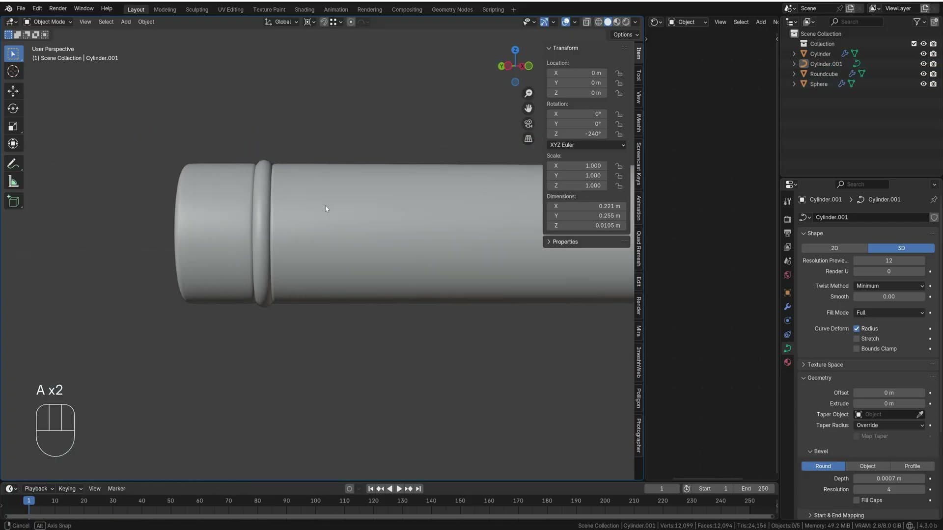
Right click the new object and choose Convert to Curve. A new Object Data Properties tab appears with the curve icon, and inside it you'll find a Geometry → Bevel section. Type 0.001 for the depth. Too thin to see at first. Push it to 0.008, which reads as a chunky ring, then dial it back to around 0.007 so the rubber just starts to show as a defined edge rather than a heavy band.
Right click the curve and pick Shade Smooth. You've now got a tidy rubber ring wrapping each foot, ready to take a separate rubber material later. With the base detail done, the only remaining piece of geometry is the power wire coming out of the back leg.
Modelling the power wire with a bezier curve
Drop a bezier curve from the rear leg, set a geometry bevel for thickness, extrude control points across the table and use Ctrl+T to twist them so the cable looks natural.
Bezier curve from the rear leg
With the lamp body finished, the next job is the power cable. Start by rotating the base so one of the rear legs faces cleanly away from the table. Select the lamp, press A then R and rotate by 30 degrees. Work in increments of 30, 60 or 120 until the trailing edge points straight out, ready for the wire to drop from.
Drop the 3D cursor onto the face the cable will exit. Tab into edit mode, press 3 for face select, click the rear face on the leg, then run Shift+S → Cursor to Selected so the cursor snaps to its centre. Tab back out of edit mode.
Now add the curve itself. Press Shift+A → Curve → Bezier and the curve appears at the cursor. Scale it right down so it sits sensibly against the leg, then Tab into edit mode to start shaping it.
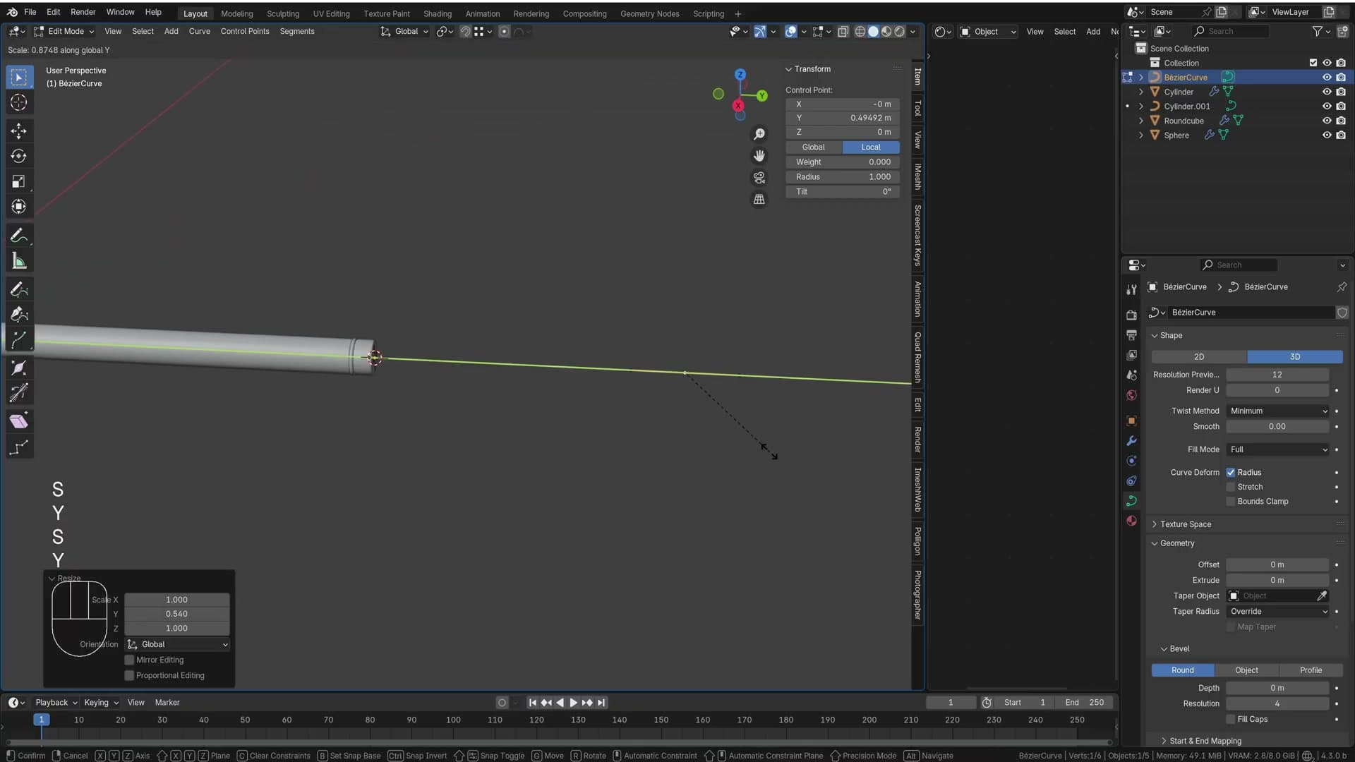
Rotate the curve on the Z axis by -90 degrees so it lies along the table, scale it in tighter and slide it over to meet the edge of the leg. Switch the transform pivot to Median Point, then rotate on Z again by -45 degrees to angle the cable away from the lamp at a believable exit angle. Turn off proportional editing before tweaking the handles, then press S Y to shrink the bezier handles on the Y axis and G Y to nudge the end point right onto the edge of the leg.
Curve geometry bevel and extrude
The curve is still a flat path with no thickness. To give it body, open the curve's Object Data Properties, expand Geometry → Bevel and dial up the depth until the wire reads at the right gauge. The whole path sweeps into a tube in one move. No need to model a cylinder and follow it along.
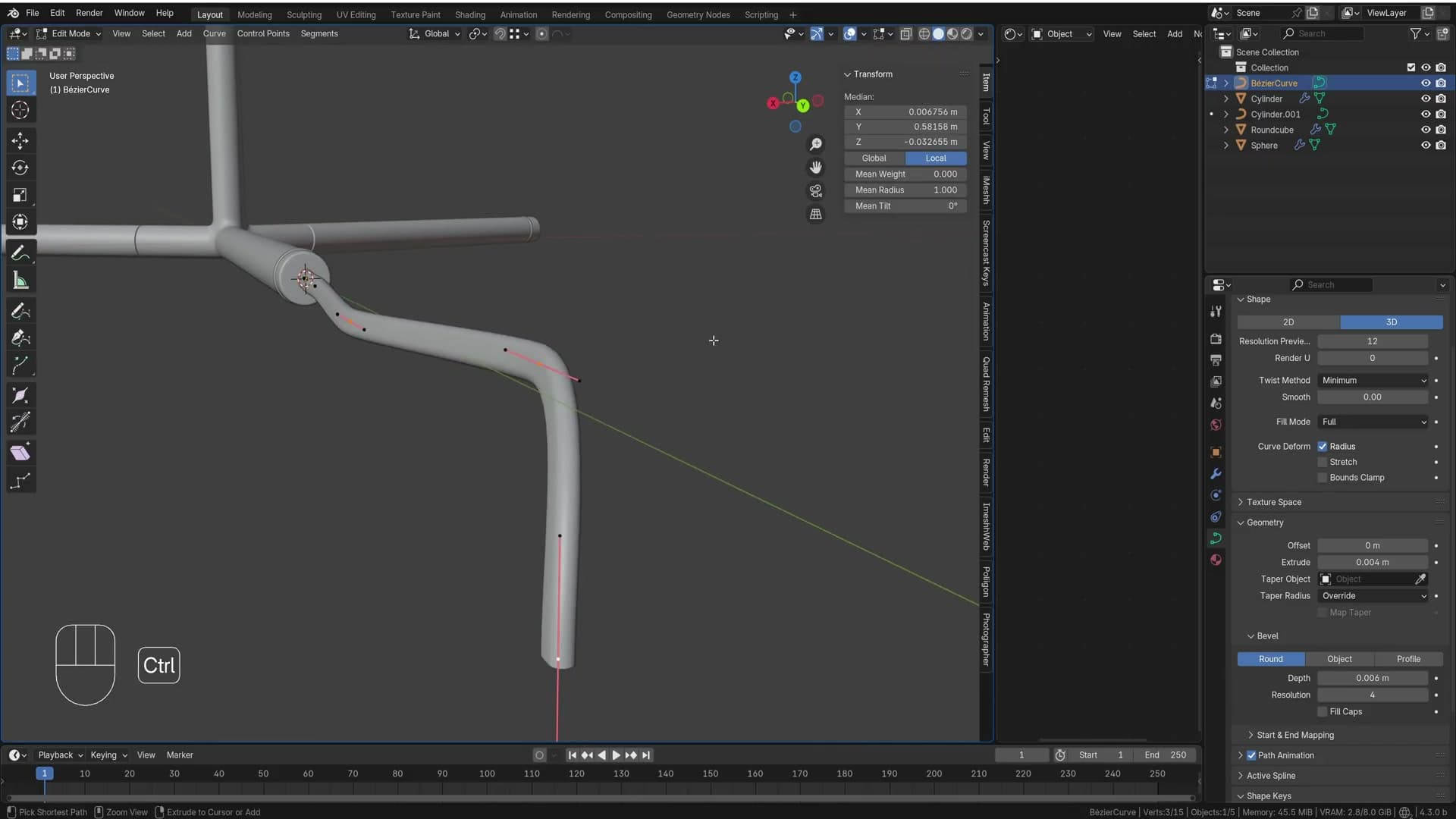
Real cables are rarely the same length on both ends, so extend one side. With the end control point selected, hold Shift and click the extrude option (or press Shift+E) to add fresh control points further along the path. Each new point lets you redirect the wire. Keep extruding across the surface of the table until the cable lands roughly where a plug would sit.
Don't fuss over making the curve perfectly smooth. As Kristian puts it, wires are never smooth in real life, so a slightly uneven, randomised shape reads more naturally than a flowing arc. Tap 7 to drop into top view and shift the control points around on the horizontal plane to break up any obvious symmetry.
Twisting with Ctrl+T
A round bezier tube alone still looks too clean. Power cables tend to flatten and roll as they travel. Tab into edit mode on the curve, select a control point and press Ctrl+T. The shortcut tilts the point around the curve's tangent, twisting the cross-section like a ribbon.
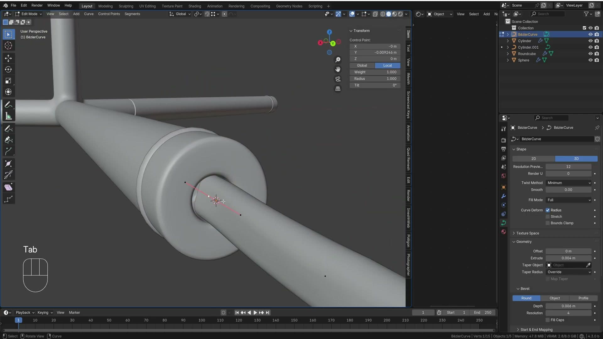
Select all the points along the wire, press Ctrl+T again and drag. The idea is that the cable leaves the leg at one angle, then gradually flattens as it lies across the table. A gentle twist along the run sells the weight of a real lead. Smooth the curve out a little where the bends look harsh and the wire is done.
UV unwrapping the lamp
Use a Node Wrangler UV grid to spot stretching, mark seams along edges the camera will never see, unwrap angle-based and scale islands for matching texel density.
Node Wrangler UV grid for diagnosis
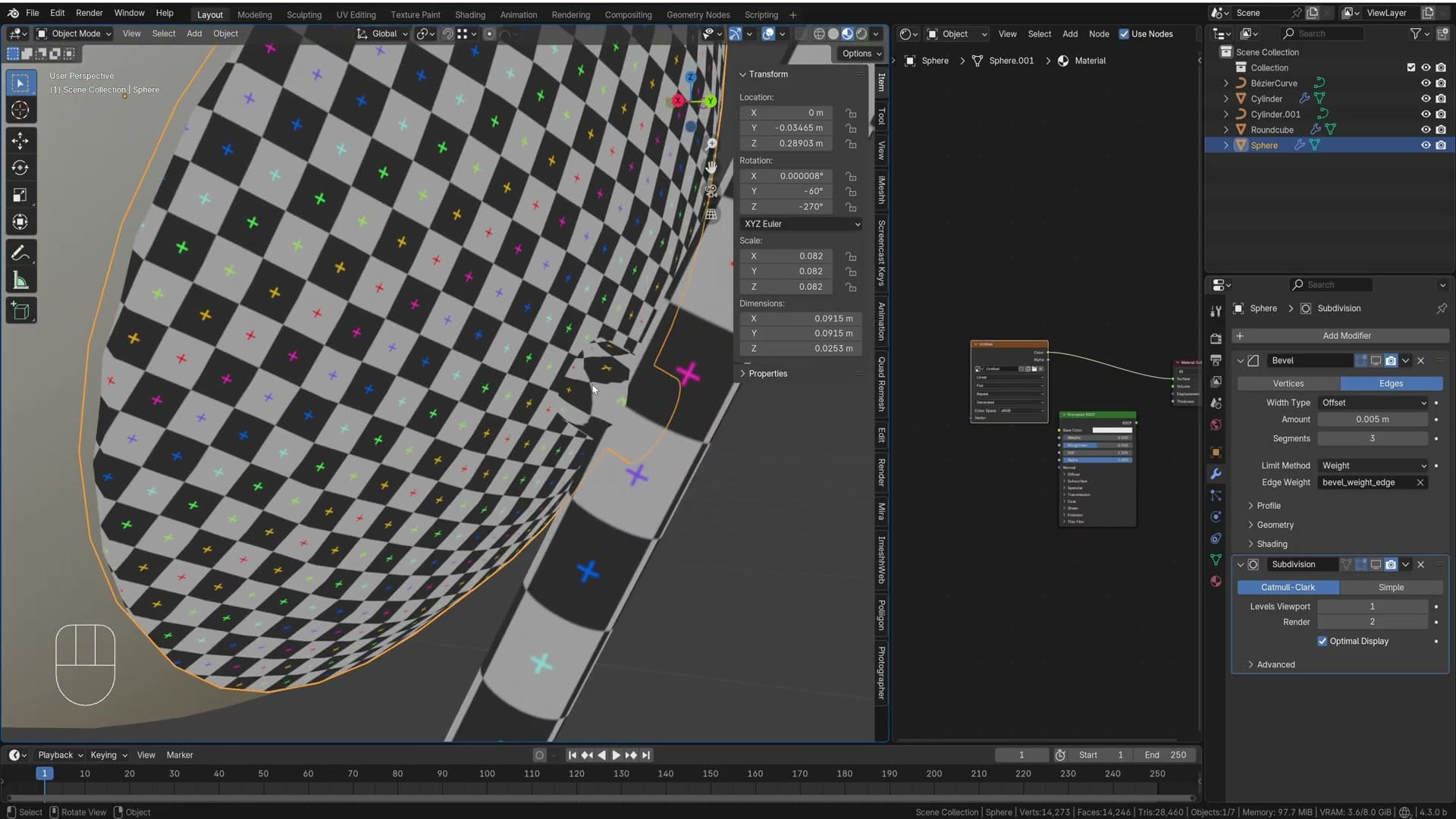
Before you can drop a real material on the lamp body, you need to unwrap it. The easiest way to see how badly the default unwrap stretches is to throw a UV grid at it. With the lamp body selected, add a new material, then press Shift+A in the shader editor and add an Image Texture node. Click New and switch Generation Type to UV Grid.
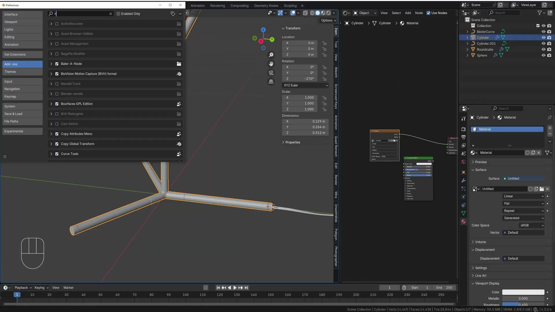
Rather than wiring that node into the output manually, let Node Wrangler do it. With Node Wrangler enabled under Edit → Preferences → Add-ons, hold Ctrl+Shift and click the Image Texture node. It solos straight to the viewer so you can preview just that node without rebuilding your connections.
Switch the viewport to Material Preview (or Rendered) and look at the lamp. The squares of the UV grid should sit cleanly across every face. On the default unwrap they don't. The grid skews and stretches across the cylinder, which tells you the mesh has no usable UVs yet. That's your cue to mark seams and unwrap properly.
Unwrap and scale islands for even texel density
Re-unwrap and inspect the grid again. The bulk of the base should look healthy, but the seam at the top often throws up odd artefacts where the subdivision surface tugs on the cut edge. The fix lives on the modifier itself: open the Subdivision Surface modifier and tick Keep Corners. That tells subsurf to respect the seam corner instead of rounding it off, and the stretching at the join settles down.
Now move to the long arm that holds the bulb. Select the lamp body, Shift+Click the arm, and press Ctrl+L → Link Materials so the arm inherits the same UV grid material. That way you can diagnose its unwrap with the same diagnostic texture. Drop into edit mode on the arm and check where the squares stretch.
The arm needs its own seams. Pick a corner that will face away from the camera and mark a seam down its length. Add another seam across the top of the arm where the view almost never reaches. If you find internal faces buried inside the connector (geometry that's physically sealed away), select them and press X → Faces to delete them outright. They'll never be seen, and removing them stops the unwrap algorithm from wasting UV space on geometry that doesn't matter.
Re-run A, U, Unwrap. The grid squares across the arm should now be close in size to the squares on the base. That visual match (every square roughly the same scale across every part of the mesh) is texel density, and it's what makes a single tiled material read consistently across the whole lamp instead of looking finer on one part and coarser on another.
Applying the iMeshh chrome material
Append the chrome shader from a downloaded .blend, tune the mix factor and normal strength, then add Ctrl+R loops near transitions to kill subsurf pinches the glossy material exposes.
Append chrome material from the iMeshh inflatable dog
With the UVs scaled to a sensible size, the legs are ready for a material. Rather than building a chrome shader from scratch, you can borrow one from the iMeshh free library. Head to the free category on imeshh.com, log in, and download the asset. It ships with a premade chrome shader that suits this lamp nicely.
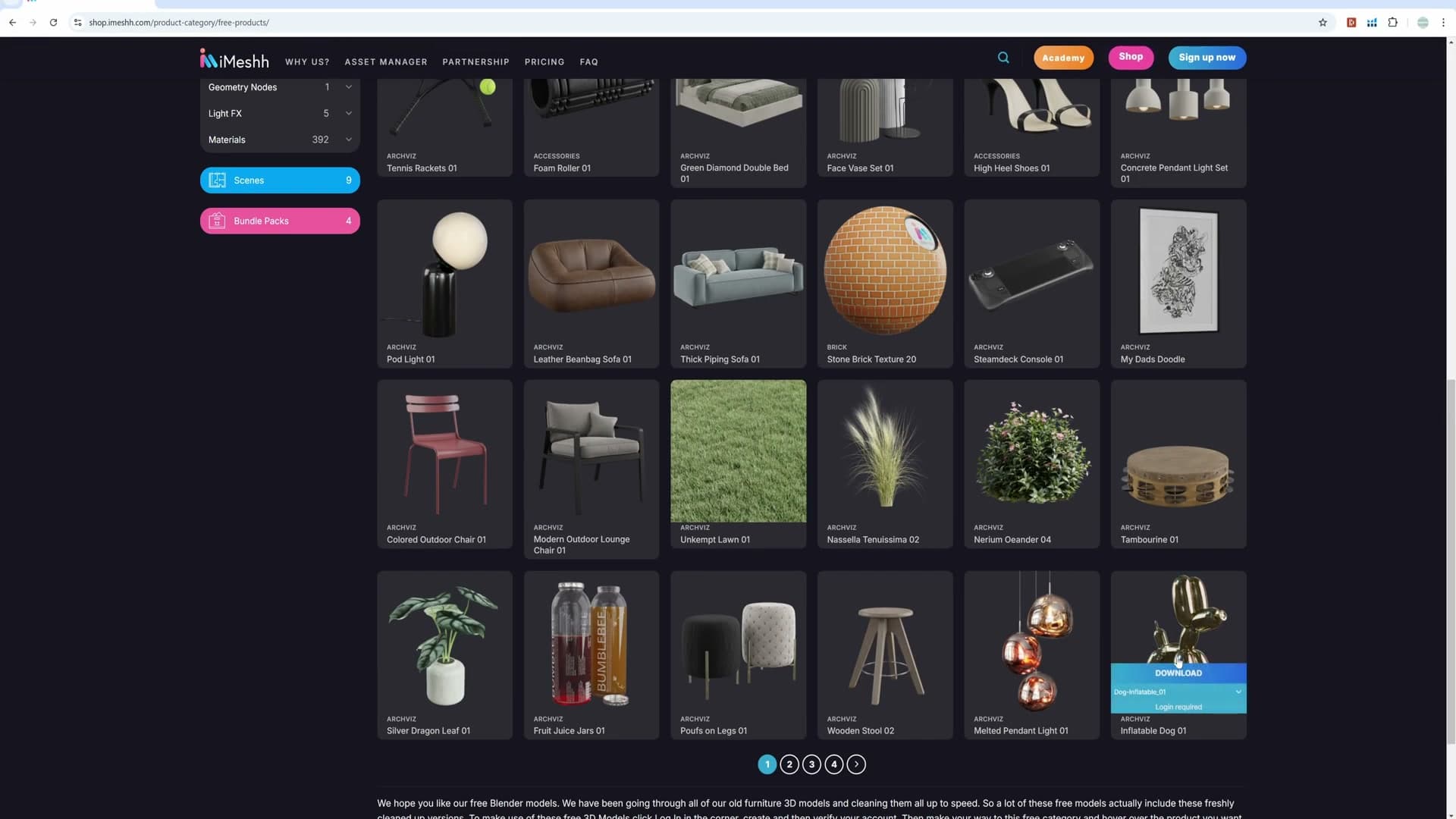
Back in Blender, open File → Append and navigate to the downloaded file. Double-click the .blend, then open the Material folder inside. Pick the chrome shader. The name reads more like a gold than a chrome, but it's the right one for this build.
With the material appended, click the leg you want to shade and assign the chrome shader from the material slot. To share the same shader with the rest of the legs, select them all, make the shaded leg the active object, and press Ctrl+L → Link Materials. Every leg now wears the same chrome.
Tweaking mix factor and normal strength
The final render will go through Cycles, so switch to Rendered viewport shading now. Eevee's material preview will lie to you about how chrome behaves. Open the Shader Editor so you can see the appended node tree.
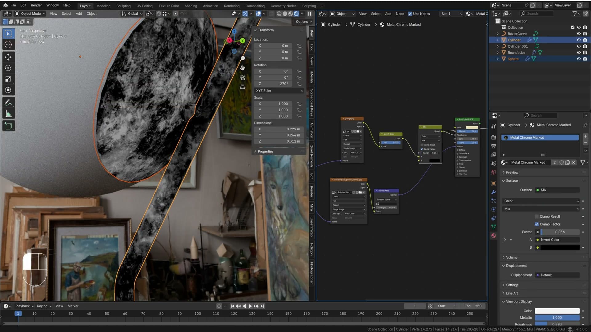
The shader uses a base texture mixed with a darker copy of itself via a Mix node. Slot A is the original texture and slot B is the black version that adds the glossy darkening. Reduce the Mix Factor so the result leans further toward slot A. Keeping a touch of dirt is fine, it just shouldn't dominate. Drop it until the chrome reads cleanly across the legs without going completely uniform.
Find the normal map node feeding the Principled BSDF. It was dialled in very weak by default, so push the normal map Strength up to 1 to bring back the fine bump detail across the surface. Toggle it off and on again and you'll see the subtle micro-roughness it adds.
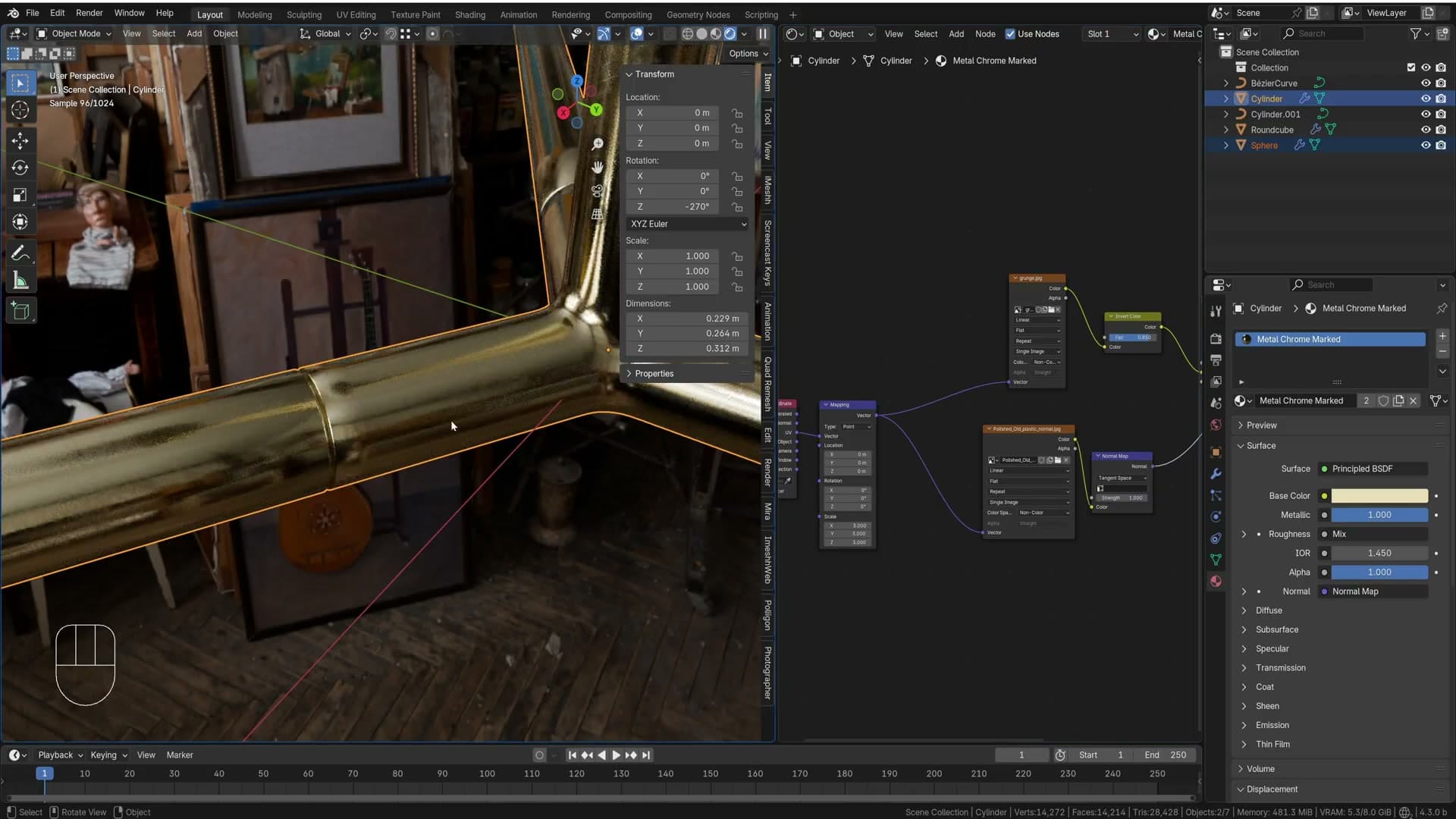
Finally, scale the texture itself smaller by raising the mapping or texture coordinate scale to around 3. Smaller texture features read as a tighter grain on a glossy surface, which suits this chrome better than the larger default tiling. With those three tweaks (mix factor down, normal strength up, texture scale up) the appended shader fits the lamp without rebuilding a single node.
Extra control loops to fix subsurf pinches
Switching to Cycles immediately exposes a problem the matte preview hid: pinches and triangulation artefacts along the leg transitions. They were always there in the geometry, but a glossy chrome surface throws them straight at the camera. The fix is more support geometry near the trouble spots.
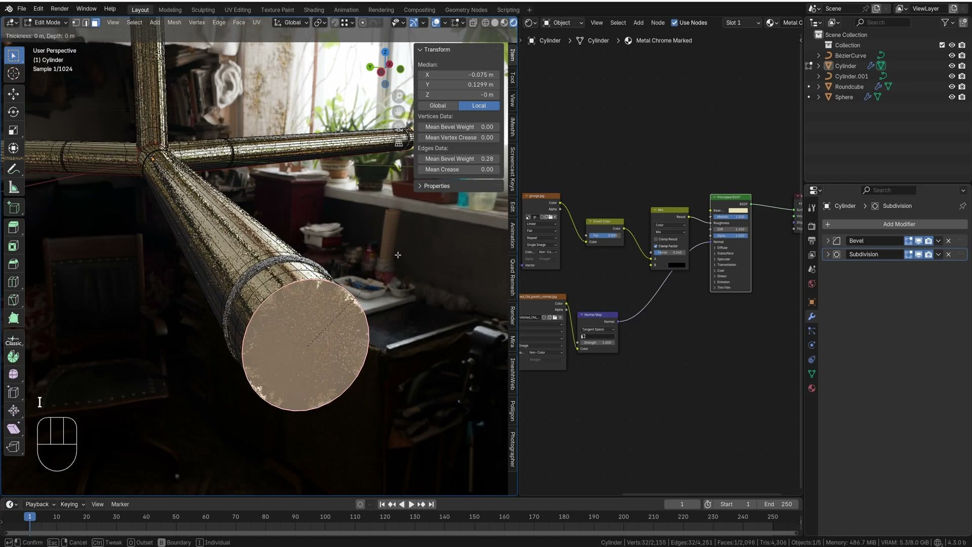
Tab into Edit Mode and press Ctrl+R to drop a fresh loop alongside each pinched edge. Slide it close to the existing transition. The closer the loop, the tighter the corner and the less the subsurf rounds it off. Walk around the legs and add loops wherever the chrome reveals a smear: near the upper joins, around the leg ends, and anywhere else the highlights bend unnaturally.
If you're conscious of poly count, there's an alternative: add a Weighted Normal modifier instead. It straightens out the shading on the existing edges without adding geometry. The trade-off is that weighted normals tend to make corners read very sharp, where real-world chrome has a softer micro-bevel. For this lamp the extra loops win on look, but either route is valid.
At the very ends of each leg you'll see the n-gon triangulate into a star pattern, which the chrome catches as a bright artefact. Select the offending end face, press I to inset a smaller face inside it, and the extra ring of quads gives Blender the structure it needs to keep that cap totally flat. Repeat on the top side of any leg showing the same star, and the chrome reads smooth all the way to the tip.
Creating the emissive light globe
Emission with a coat layer fakes glass cheaply. Blackbody at 2800 K warms it; Layer Weight Facing through a flipped Color Ramp drives a halo falloff that sells the bulb without real glass.
Emission with a coat layer
With the bulb material set up on the globe geometry, the goal is to make it read as a lit lamp rather than a flat sphere. On the Principled BSDF, scroll down to the Emission section and set the Emission Strength to 1 so the surface starts to glow.
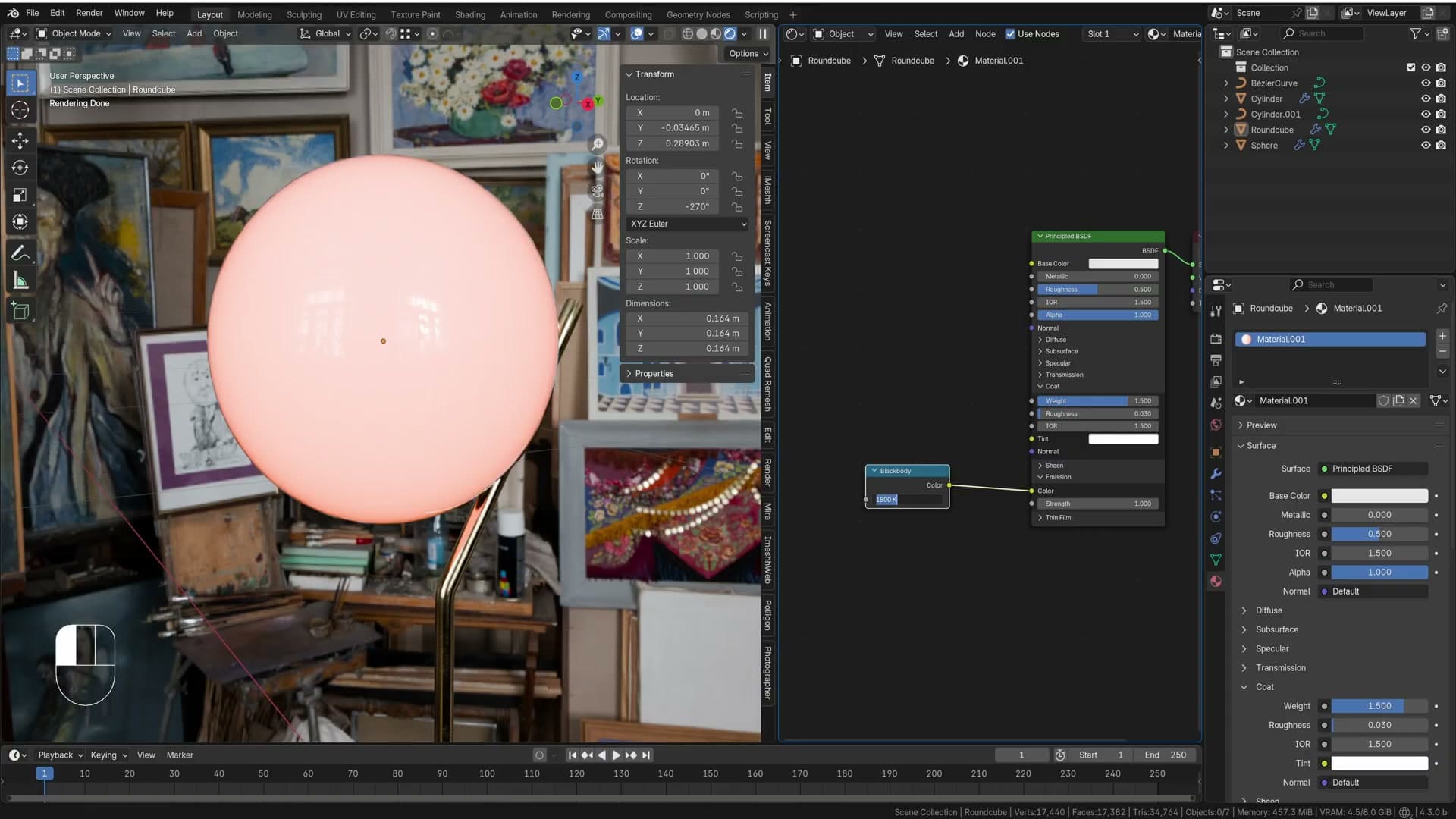
On its own that gives you a perfectly even, plasticky emitter. To suggest a thin glass shell wrapping the light, open the Coat section of the same Principled BSDF and push Coat Weight up to 1.5. That overdriven coat produces a faint glossy ring around the silhouette of the sphere. It reads like the highlight you get from looking at the edge of a real glass bulb, without any extra geometry.
Blackbody colour for warm light
Tungsten bulbs are warm, not pure white, so the next step is to drive the emission colour from a colour temperature rather than picking a swatch by eye. In the shader editor, click and drag out from the Emission Colour socket and add a Blackbody node.
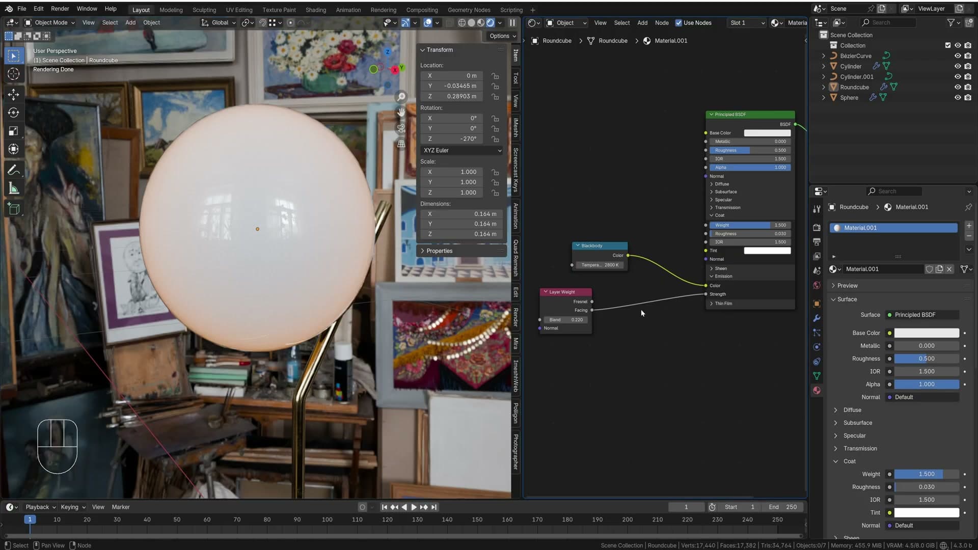
Blackbody works in kelvin, the same scale most real-world lights are rated in. Set the Temperature to 2800 and the bulb takes on a warm orange tungsten cast. You can nudge this higher for a cooler modern bulb or lower for something more candle-like, but 2800 K is a safe starting point for a domestic desk lamp.
Layer Weight + Color Ramp halo falloff
The bulb is now warm and glowing, but it still looks like a flat sphere with an emission shader rather than a glass globe with a filament inside. The trick is to fall the emission off towards the silhouette so the centre of the sphere reads brightest and the rim reads darkest. That's how a backlit glass shape behaves in real life.
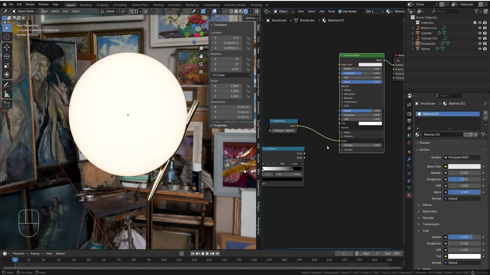
Add a Layer Weight node and plug the Facing output into the Emission Strength socket. Out of the box this falls off the wrong way: the rim of the sphere ends up bright and the centre dark. To flip it, add a Color Ramp node between Layer Weight and the strength input, then swap the positions of the black and white handles so the gradient runs the other direction.
With the ramp reversed you get a proper halo: a bright centre that softens to a dark edge. Drag the handles inwards to tighten the halo. Pull the black handle in to extend the dark rim and the white handle in to keep the bright core punchy. Bring them too close together and it starts to look like a glass ball with a separate light source floating inside, which is a happy side effect of the setup.
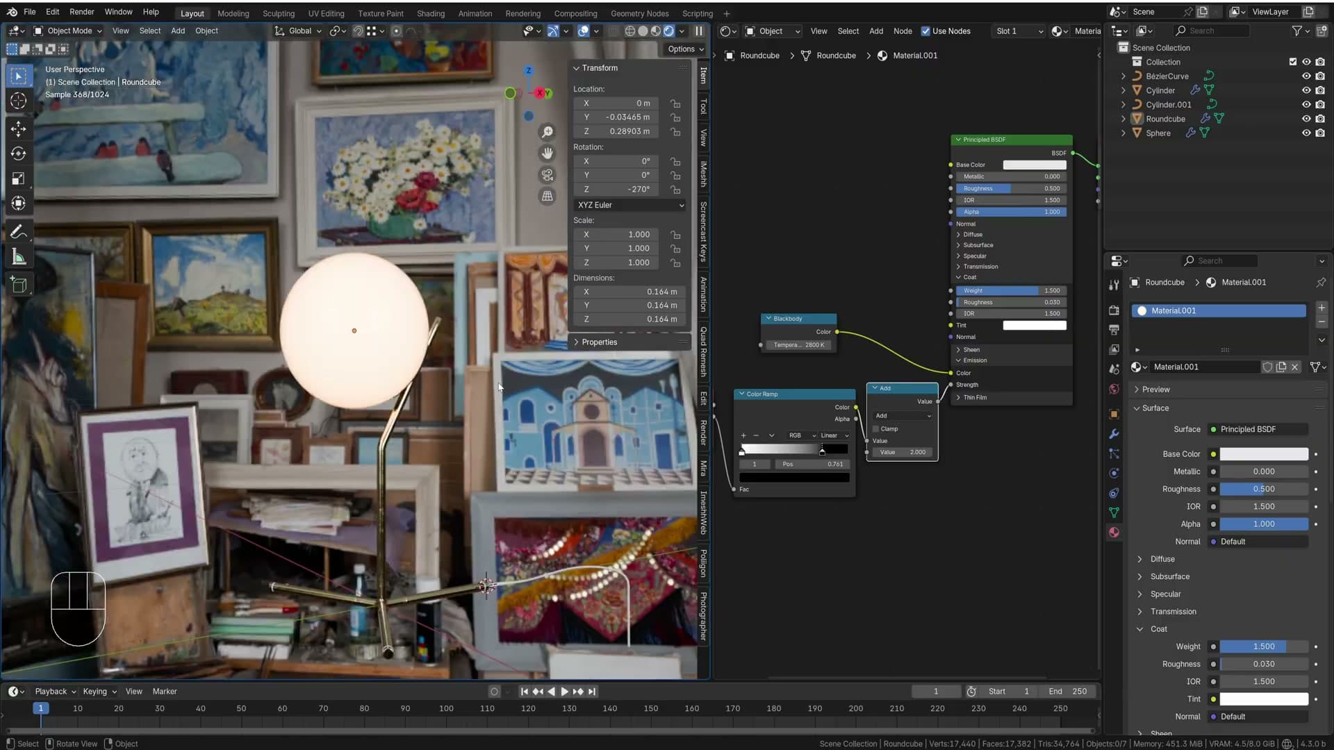
One last problem: a Color Ramp only outputs values between zero and one, so the strength is capped at 1 and you cannot make the bulb any brighter from that node alone. Drop in a Math node set to Multiply, route the ramp through the first Value socket, and type a number into the second. A value of 2 is enough to make the globe sit confidently above the rest of the scene without blowing out the edge halo. The end result reads as glowing backlit glass in Cycles and renders far cheaper than modelling an actual glass shell with a real emitter inside.
Finishing with plastic feet and parenting
A quick black plastic shader gets linked to the rubber feet and connector; viewport display colours separate the parts. Ctrl+P keeps the whole lamp moving as one object.
Quick black plastic material
The rubber feet and the connector ring at the top of the pole still carry the default material, so they need their own shader before the lamp is finished. With one of those parts selected, hit New on the material slot and dial the Base Color down to black. Kristian flags that you could unwrap these pieces and reuse the chrome material with metallic switched off, but for an asset this small a plain non-metallic black does the job.
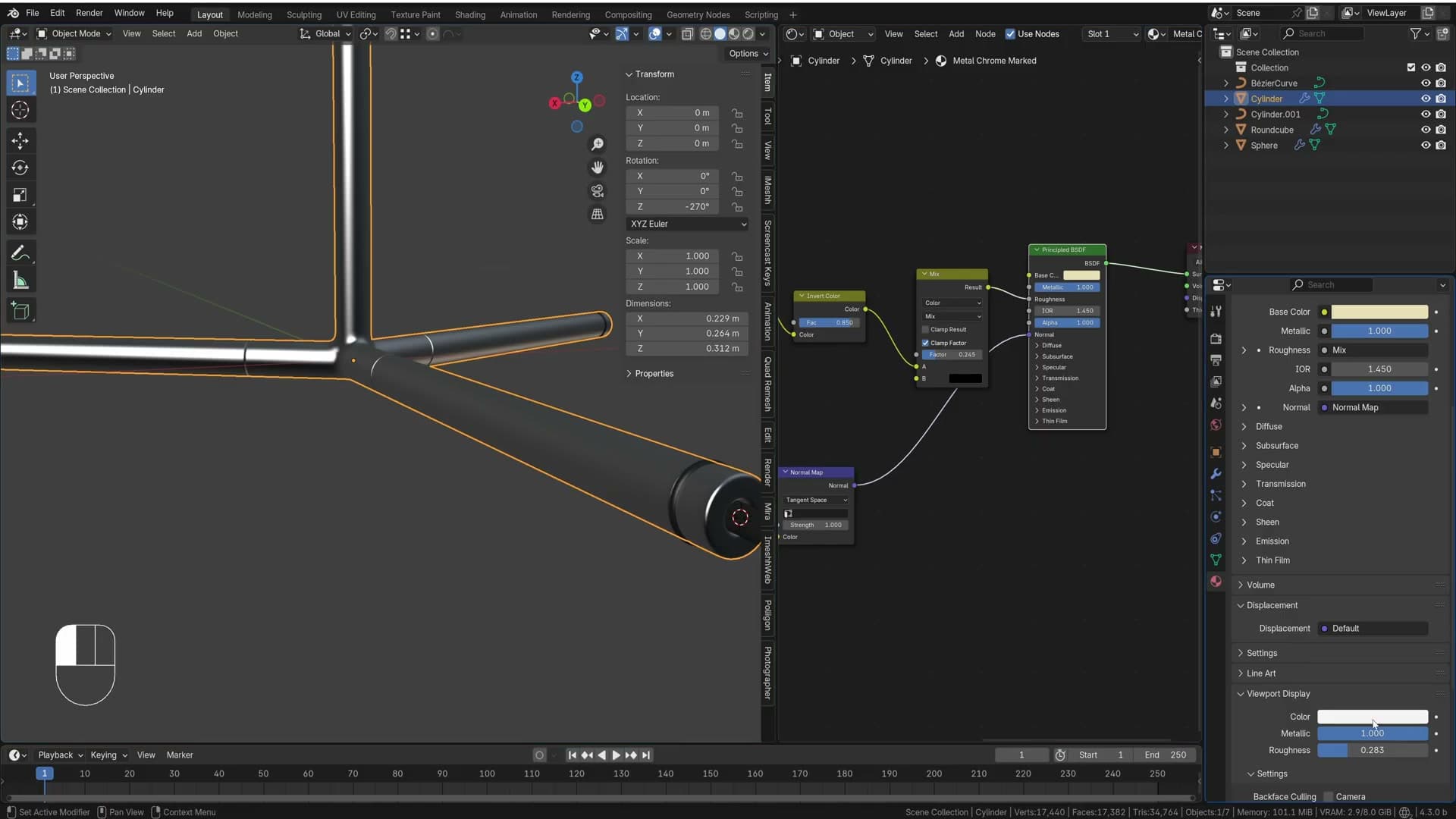
Rather than build the same shader twice, select the remaining plastic parts, then shift-select the one you just shaded so it becomes the active object, and press Ctrl+L → Link Materials. Every selected object now shares the same datablock, so any later tweak to roughness or colour propagates across all of them.
Solid viewport shading still draws everything in the same default grey, which makes it hard to see what's what while you work. Open the material's Viewport Display panel and set the colour swatch to black for the plastic, and to a warm gold for the connector and bulb fitting that are actually using the chrome shader. The parts now read at a glance even before you switch to a rendered view.
Parenting every part to the base
The lamp is currently a loose collection of objects, so moving it onto a scene means dragging each piece individually. Parent everything to the base instead. Press A to select all of the lamp's parts, then shift-click the base last so it becomes the active object. The parent always has to be selected last. Hit Ctrl+P and choose Object (Keep Transform).

Now grabbing the base drags the globe, pole, connector, feet and wire along with it, ready to drop onto whatever table or shelf you want to render it on. That wraps the build. You have a complete, non-destructive desk lamp that you can pose, light and render however you like.
Tools and credits
Everything mentioned in this tutorial, with links.
- Blender (the renderer this entire build runs in).
- iMeshh (studio platform for project management, client review, asset library and invoicing). The asset library used in this tutorial is included with every iMeshh Pro plan.
- Poly Haven (free CC0 textures and HDRIs).
Pillar guide: Scene Builds hub