Meet the iMeshh pipe system
A quick tour of what the iMeshh pipe rig is, why low-poly mode matters when you're editing it, and what the underlying mesh actually looks like under the geometry nodes.
What the iMeshh pipe system is
The iMeshh pipe system is a procedural rig bundled into the paid iMeshh library. It uses geometry nodes to turn a handful of vertices into a complete run of pipes (connectors, corner parts, supports and all), and it works as a neat showcase of what geometry nodes can do for archviz scenes, whether or not you have access to the rig itself.
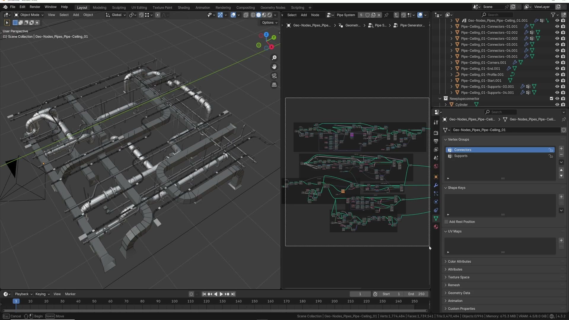
Credit where it's due: I didn't build this rig myself. It was put together by an outside geometry-nodes specialist whose knowledge of the node tree runs far deeper than mine.
Because the system is effectively a piece of code built out of nodes, it has rough edges. The biggest one is Blender's curve behaviour. If the rig decides a curve should run in one direction and a stray vertex sits in the wrong place, the whole run can flip orientation. That quirk comes up several times later in this walkthrough. The build shown here is the best version available right now, and a version two is on the cards.
Why low-poly mode exists
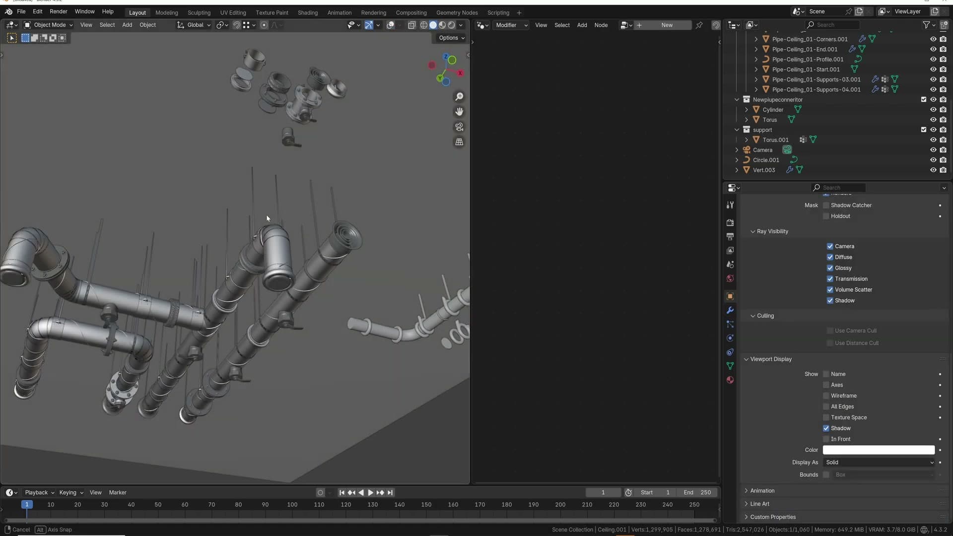
A long pipe run with lots of instanced connectors, corner parts and supports can drag the viewport down. Every edit you make to the underlying edge chain forces the geometry-nodes rig to rebuild all of that detail. That's where low-poly mode comes in.
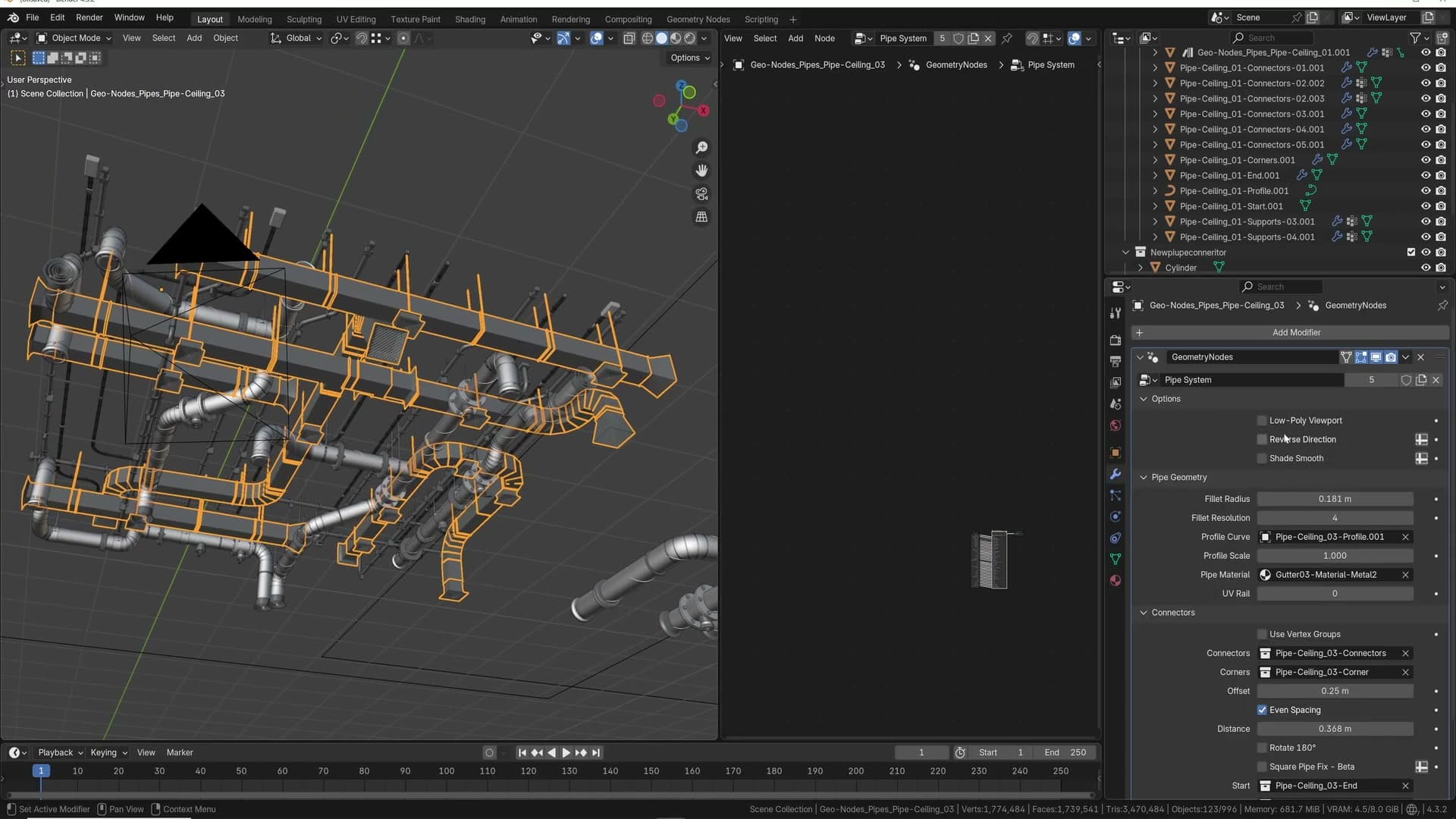
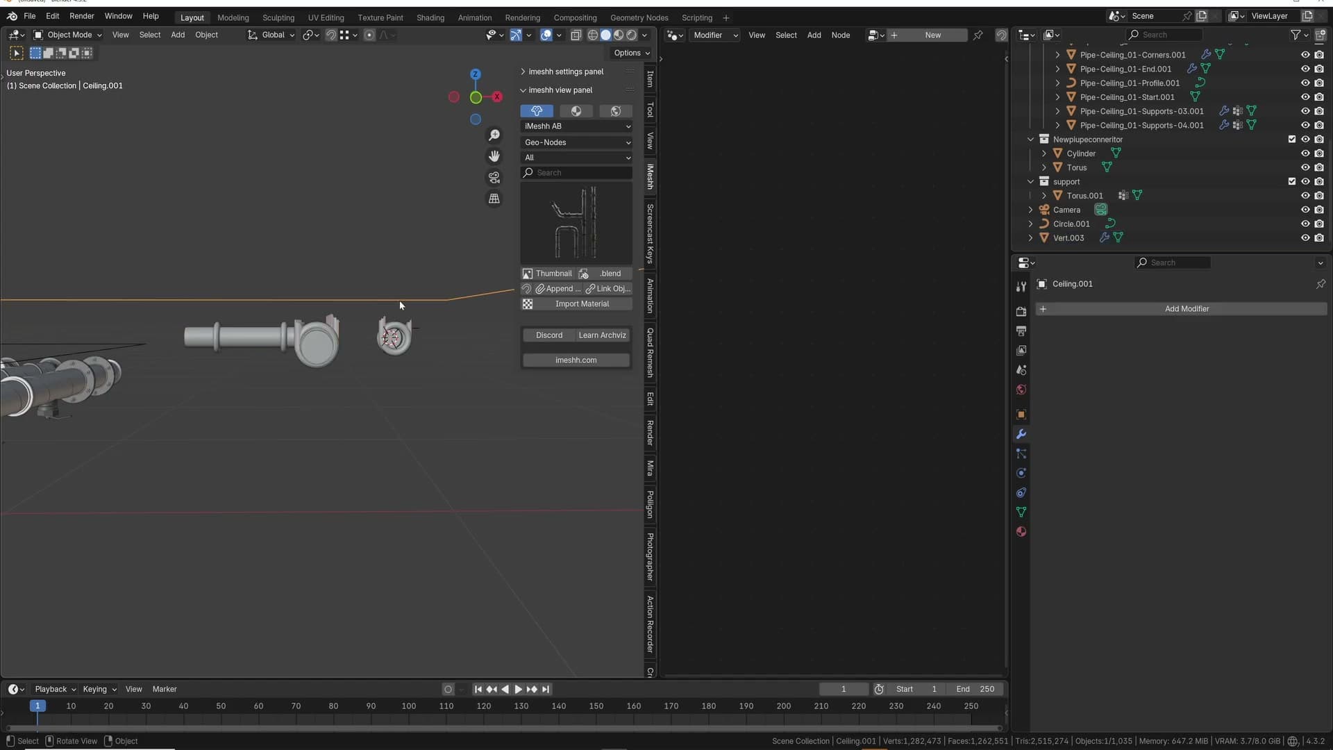
Toggle low-poly mode on while you're editing. The viewport drops the heavy instanced geometry for lightweight placeholders, so dragging vertices, extruding new sections and reshaping the run all stay responsive.
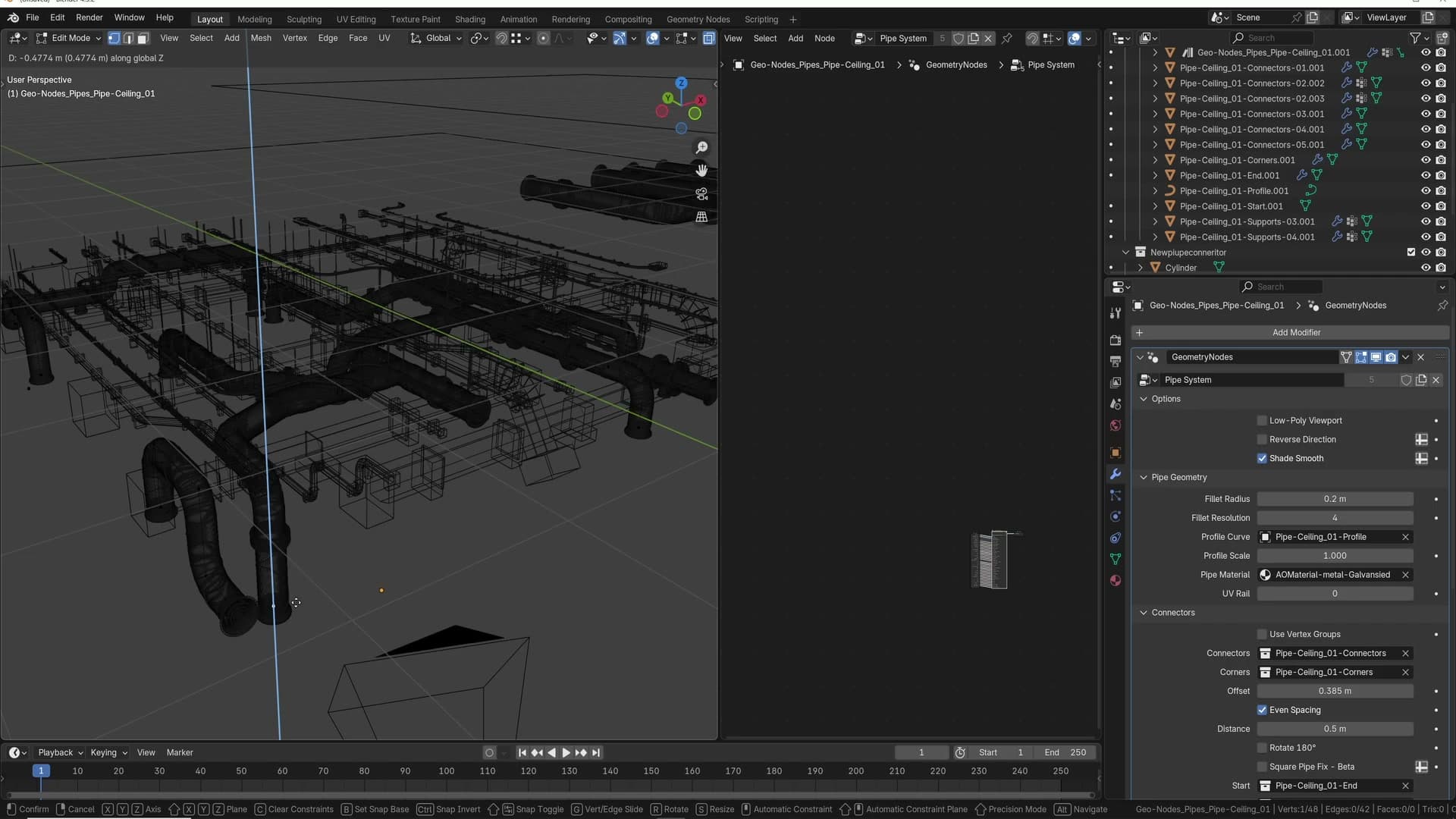
When you want to see the finished result, flip the viewport into render preview (or simply turn low-poly mode back off). There's no separate bake or generate step. The full-detail pipe renders straight away. Some of the materials also carry ambient occlusion so the connectors, corners and supports read as a single joined object rather than a stack of separate instances.
The underlying mesh is just edges
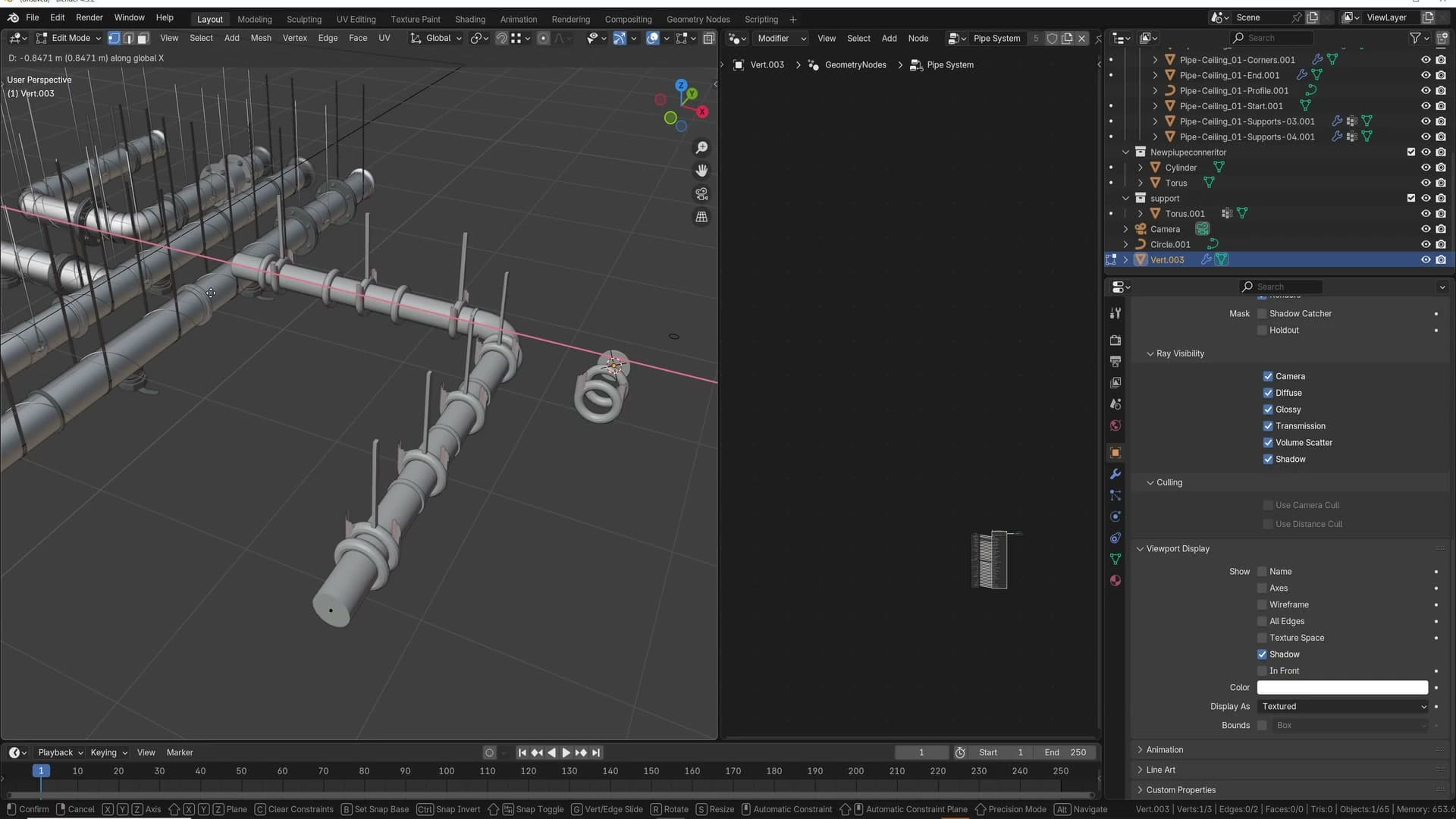
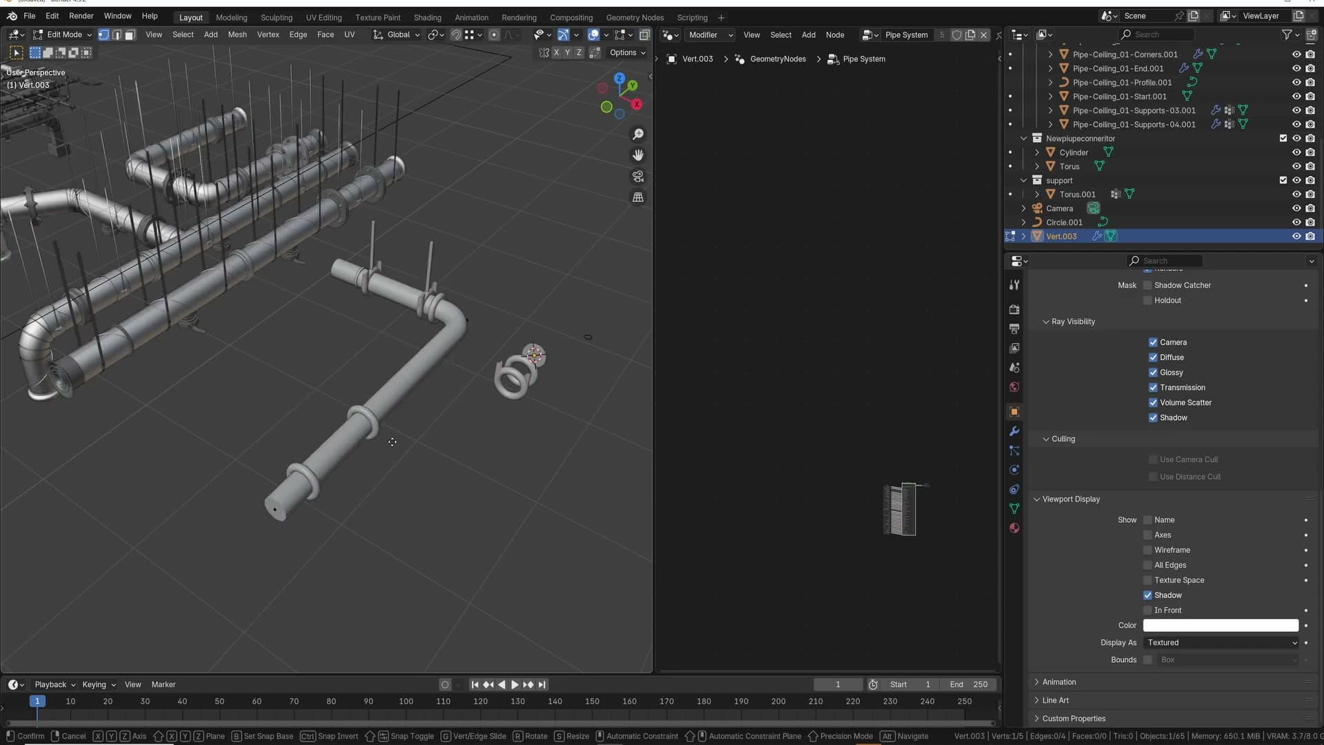
Drop into edit mode on the pipe object and you'll see something surprisingly simple: a single vertex extruded along a path, forming a plain edge chain. No curve object, no profile, no instancing. Just a sequence of vertices connected by edges.
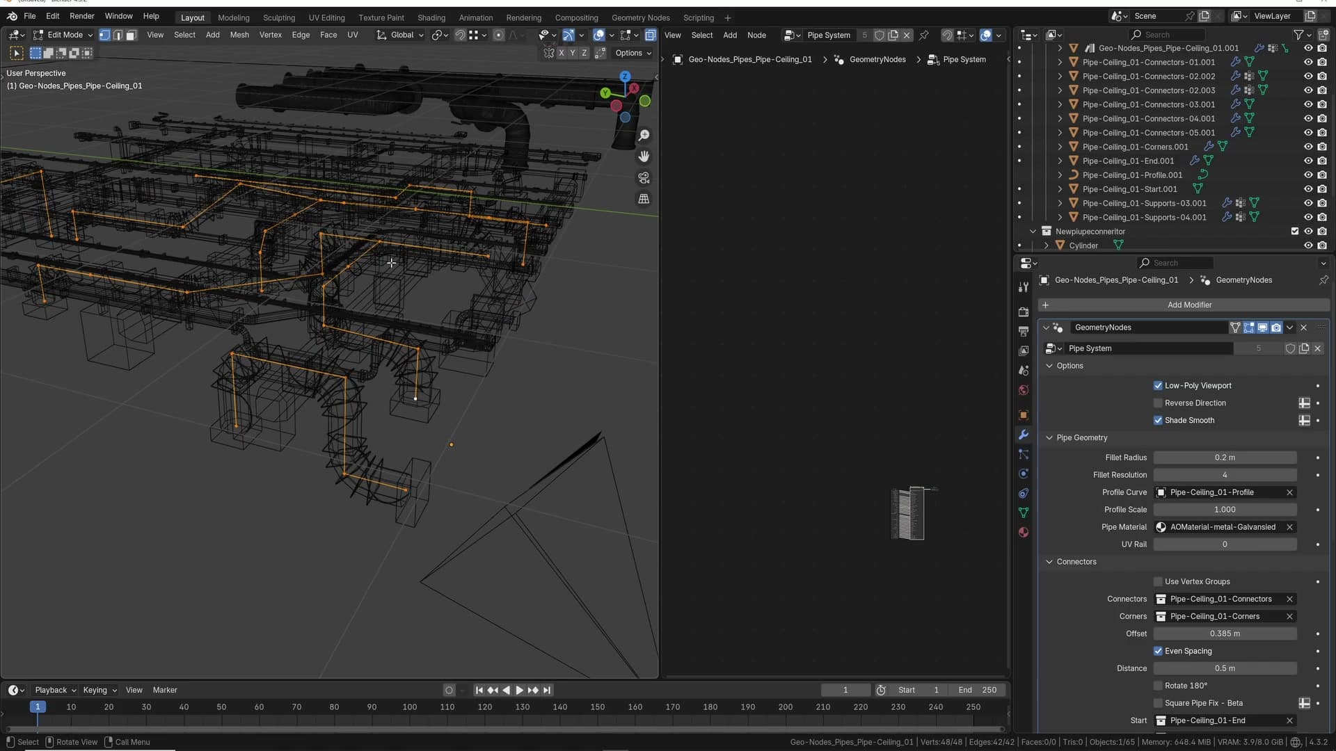
The geometry-nodes rig takes that edge chain, converts it into a curve internally, and uses the curve to drive everything else: the pipe profile, the connectors, the corner parts and the supports. You stay editing a lightweight mesh while the rig handles the curve conversion and instancing under the hood. That's exactly why low-poly mode is so effective. The source you're touching is already tiny.
Use the pre-made templates
Where to find the bundled straight, curved and T-junction presets and why you should reach for them before building anything from scratch.
Finding the iMeshh presets
Before you start building pipe runs from scratch, it is worth knowing that iMeshh ships a handful of ready-made templates so you can skip the rig-from-scratch dance entirely. Open the iMeshh menu and you will see a small set of pre-made pipe systems waiting for you.
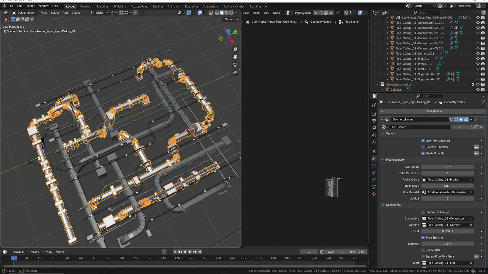
Three shapes are bundled: a straight run, a curved run and a T-junction. Each one is a complete pipe with all the supports, connectors and corner parts already wired up, so all you have to do is drop it in and reshape the underlying curve to fit your scene.
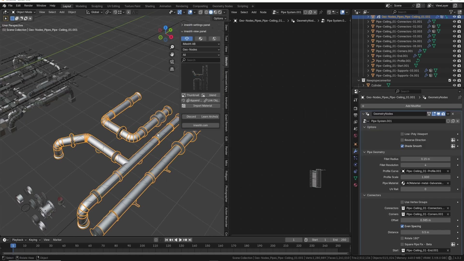
Straight runs are the easiest case and behave exactly as you would expect. Curved runs work most of the time. T-junctions are the awkward one, because of how Blender orientates the curves underneath. That's exactly why a preset exists for them in the first place.
Why the templates exist
The reason the T-junction preset exists at all is a quirk of building one yourself. If you take an existing pipe curve and extrude a new vertex out from the middle, some of the connectors and supports will simply vanish from certain branches and refuse to render. The geometry is technically there, but the rig stops distributing parts onto it correctly.
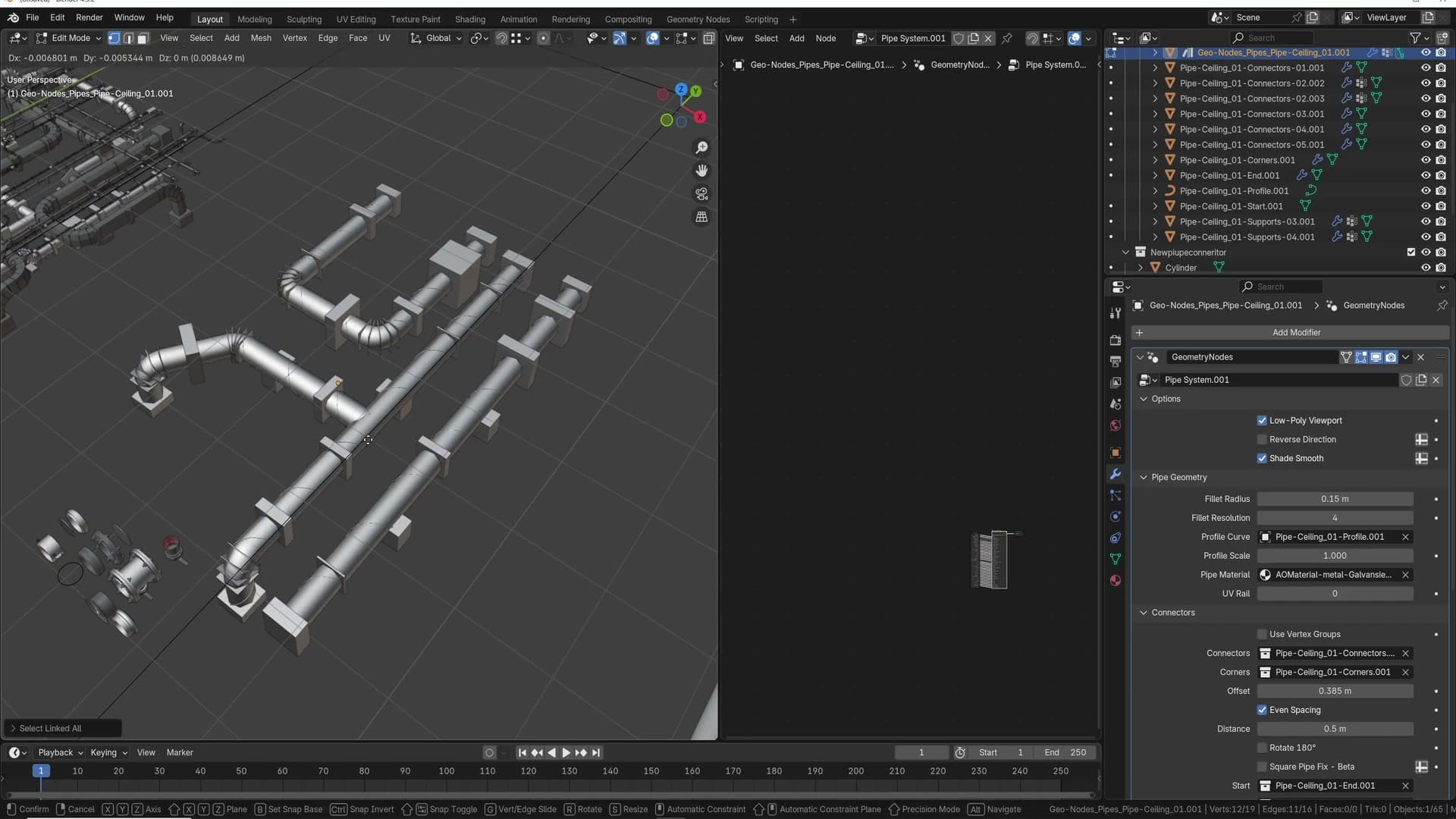
The bundled T-junction sidesteps the problem entirely. It is a configuration that has been tested and known to work, so every connector and support sits where you would expect. Reshape that template to match the layout you actually need rather than trying to rebuild the topology by hand.
The rule of thumb is simple: if you need a T-junction, reach for the preset first. Edit the existing curve to fit your scene and let the rig do the rest.
Straight runs are the exception. They're the easiest to construct from a fresh single vertex, which is exactly what the next module covers.
Build a pipe from scratch
Adding a single vertex, extruding the edge chain and assigning the Pipe System geometry-nodes setup to a fresh mesh.
Add Single Vert and extrude
To understand what the rig is actually doing, it helps to build a pipe from nothing. The starting point is always a single vertex with one or more edges extruded from it. That edge chain is the path the geometry nodes follow when they generate the pipe.
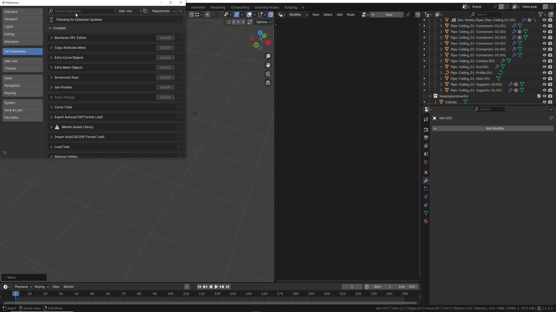
Make sure the Extra Mesh Objects extension is enabled first. Head to Edit > Preferences > Extensions, find it in the list and confirm it's installed (update it if the panel offers one). That extension is what surfaces the Single Vert option in the Add menu.
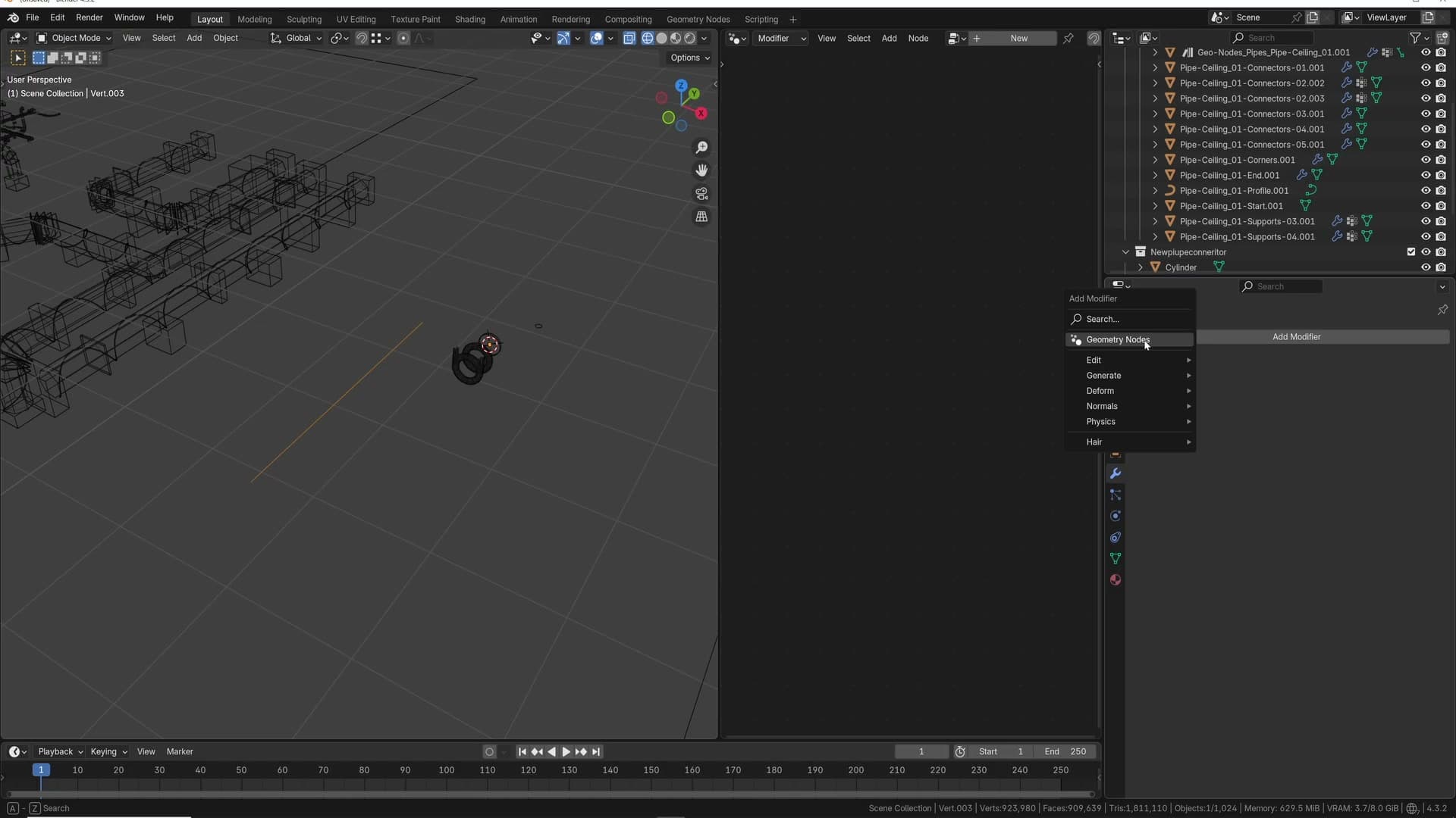
With the extension live, drop a one-vertex mesh into the scene from the Add menu's Single Vert option. Tab into Edit Mode, press E to extrude and then Y to lock the new vertex to the Y axis, and click to confirm. You're left with a single straight edge running along Y. That's exactly the input the Pipe System wants.
Assign the Pipe System geometry nodes
With the single edge selected, jump back to Object Mode and open the modifier stack. Add a Geometry Nodes modifier and, from the node-group dropdown, pick the same node group that powers every one of the pre-made systems from the previous module.
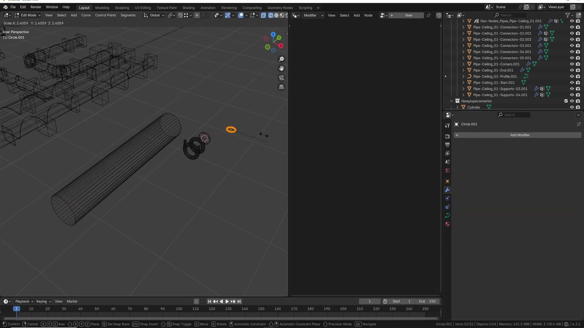
As soon as the modifier is assigned the rig needs a profile curve. The profile is the shape that gets swept along the edge chain, so it defines the cross-section of the whole pipe. Add a separate curve object to the scene (a small Bezier circle is the obvious choice for a round pipe) and point the modifier's profile input at that curve object.
From here, the profile is live. Tab into the profile curve in Edit Mode and scale it. The entire pipe thickens or shrinks in the viewport in real time. Reshape it into something non-circular and every instanced section follows. The geometry nodes are doing all the sweeping; the profile is just a normal curve you can edit at any time.
Profile curve and corner parts
Picking a profile curve to control the cross-section, then adding corner parts that decorate the bends.
Setting the pipe profile
With the edge chain converted to a pipe by the Pipe System modifier, three more slots on the rig add the visual layers that make a run look real: corner parts that decorate the bends, connector pieces that scatter along the straights, and supports that fix the run to a wall or ceiling. I'll step through each in turn, beginning with the corners.
Corner parts on bends
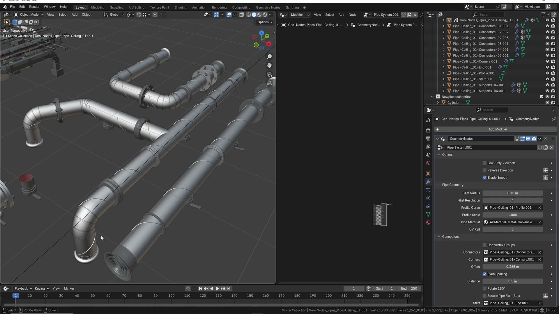
Corner parts are dedicated meshes that drop onto each bend in the run. They're the banded, slightly fussier geometry you'd expect to see on a real pipe where it turns through 90°. They're the first of the three optional layers stacked on top of the base extrusion.
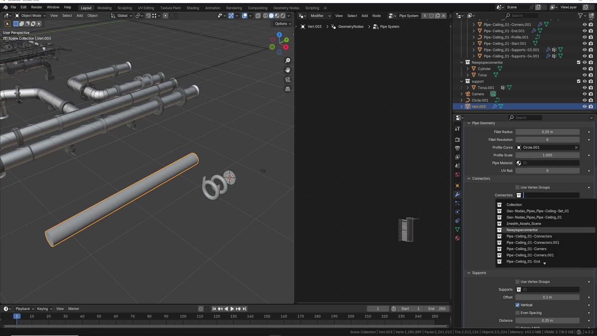
I built them into the rig deliberately. This is some nice detail, which I really wanted in this system. With a corner-part collection plugged into the modifier, every bend in the underlying edge chain gets one of those meshes placed and oriented automatically, so a long ceiling run with dozens of turns picks up the extra detail without any per-corner work.
Connectors, fillet radius and end caps
Random connector distribution, even spacing, fillet radius for smoother bends, plus the start and end cap collections that finish the pipe.
Connector collections and seed
With a connector collection ready, the geometry nodes pick one mesh from it for every point they place along the run. The collection in this example holds two connector variants, which the rig randomises between as it walks the pipe. A long straight run won't show the same elbow piece repeated end-to-end.
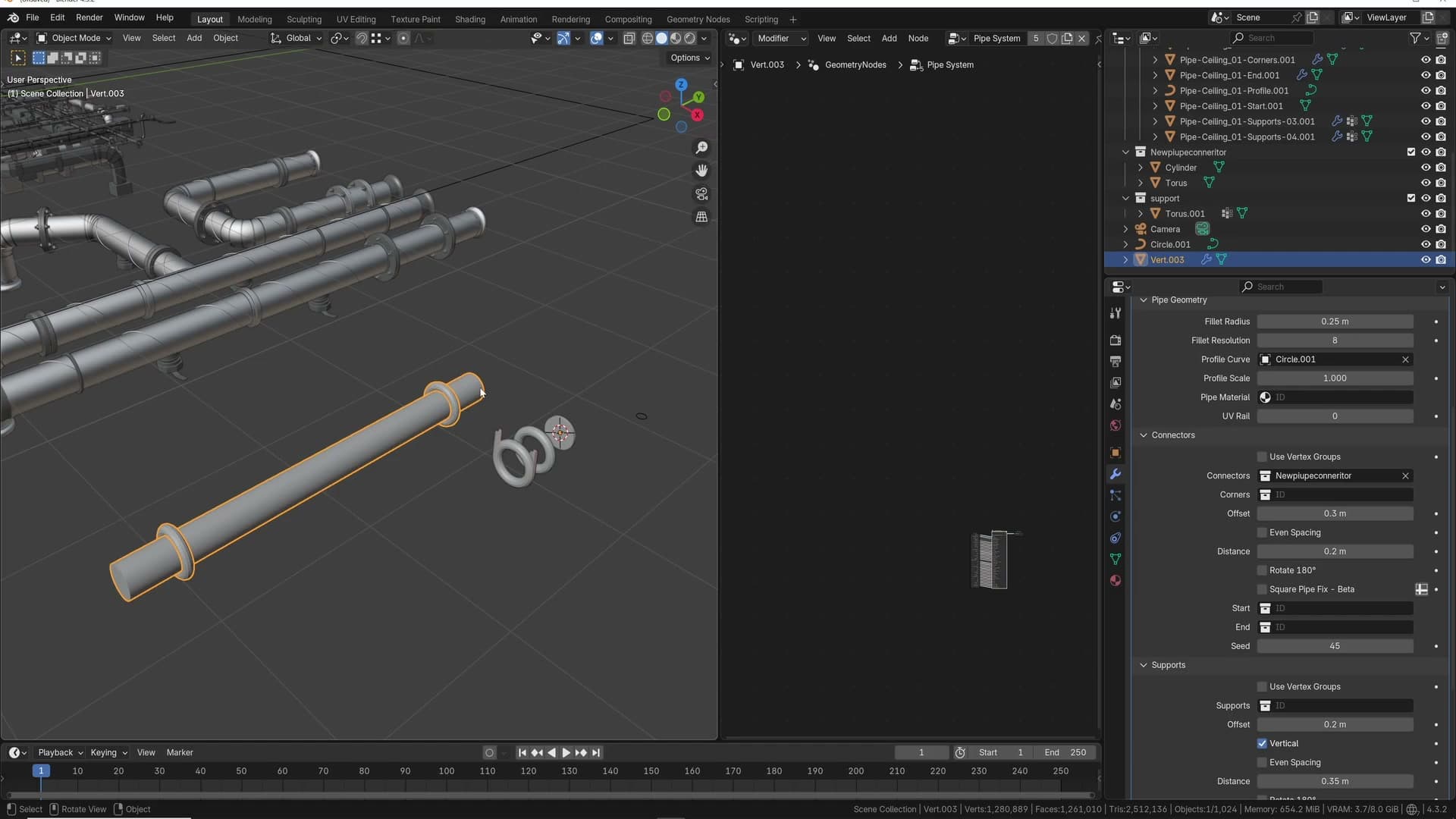
Width drives how many connectors actually appear on a typical system. I aim for about two connectors per run as a comfortable starting density. Shorter pipes might only get one, longer pipes may get more, but two is a useful target that reads well without crowding the geometry.
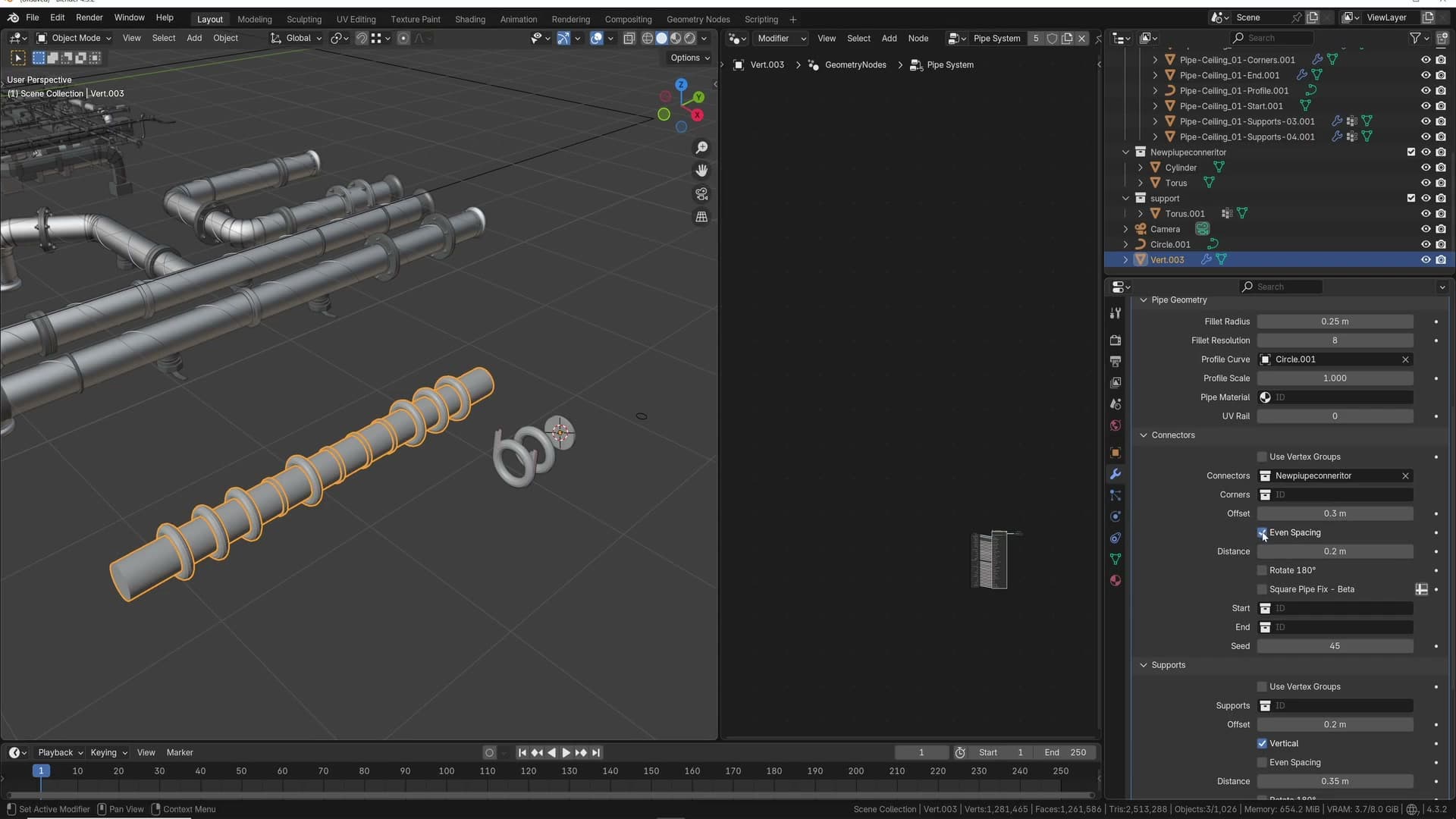
When an arrangement looks unlucky (the same variant twice in a row, or a bulky connector sitting somewhere awkward), change the seed. Reseeding reshuffles which connector lands on each point without touching the collection or the underlying curve, so you can scrub through options until the distribution feels right.
Even spacing and offset
Turn on even spacing next. I turn this on almost every time. Rather than letting the rig drop connectors wherever happens to be convenient on the curve, even spacing distributes them at a consistent interval along the whole run.
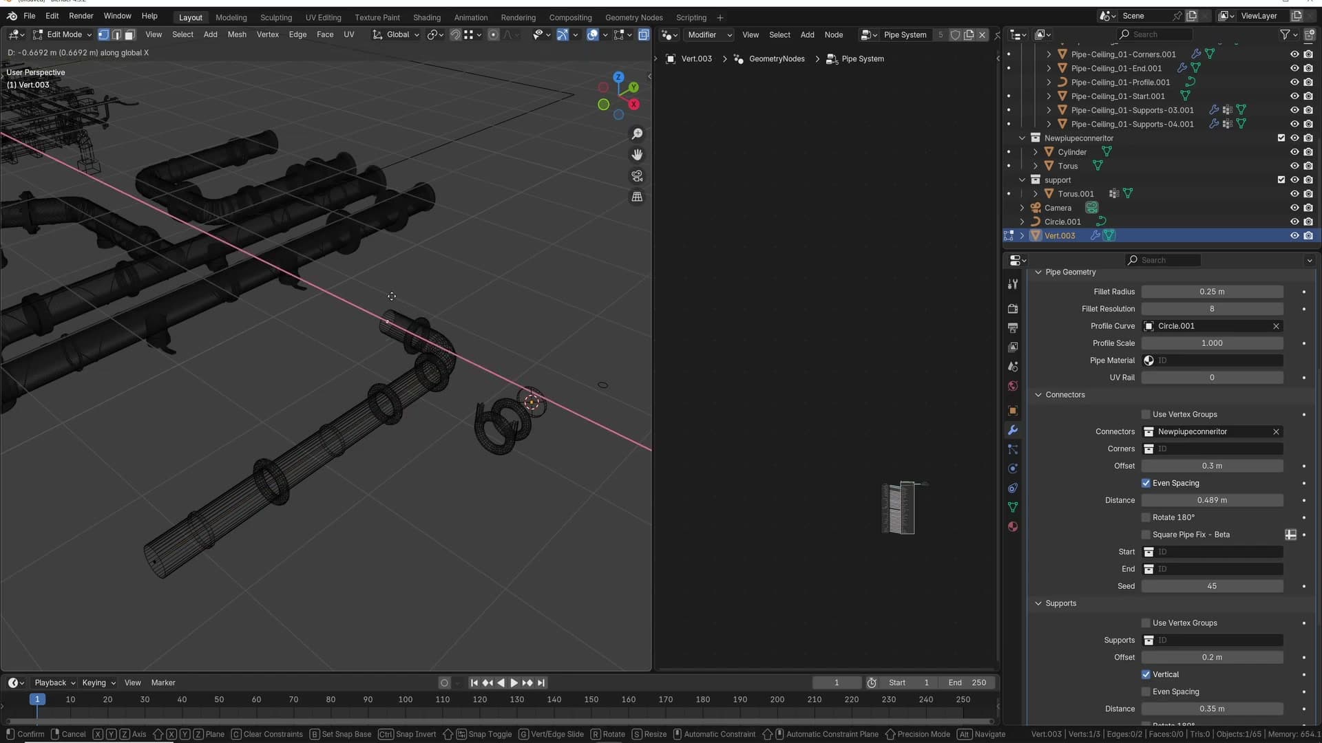
With even spacing on, the spacing (or distance) input controls how tightly packed the connectors are. Smaller values bring them closer together; larger values stretch them out across the system. Tune it visually against the length of your pipe. There's no fixed number, just what reads cleanly.
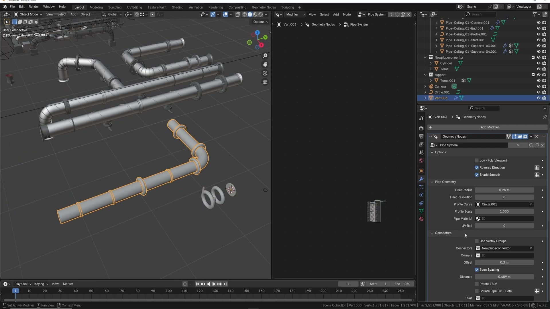
Offset is the second knob and it solves a specific problem. Without it, connectors can end up sitting on top of corner parts where two pieces meet, doubling up geometry at the bend. Increase the offset and the connectors get pushed away from those corners, leaving the bend itself to read on its own without anything piled against it.
Fillet radius for smoother bends
Back in edit mode, extruding the vertex out on the X axis adds a corner to the pipe. Out of the box that corner is a sharp 90° turn. It's a useful starting point, but rarely what you want for a finished render where pipes need to look bent rather than mitred.
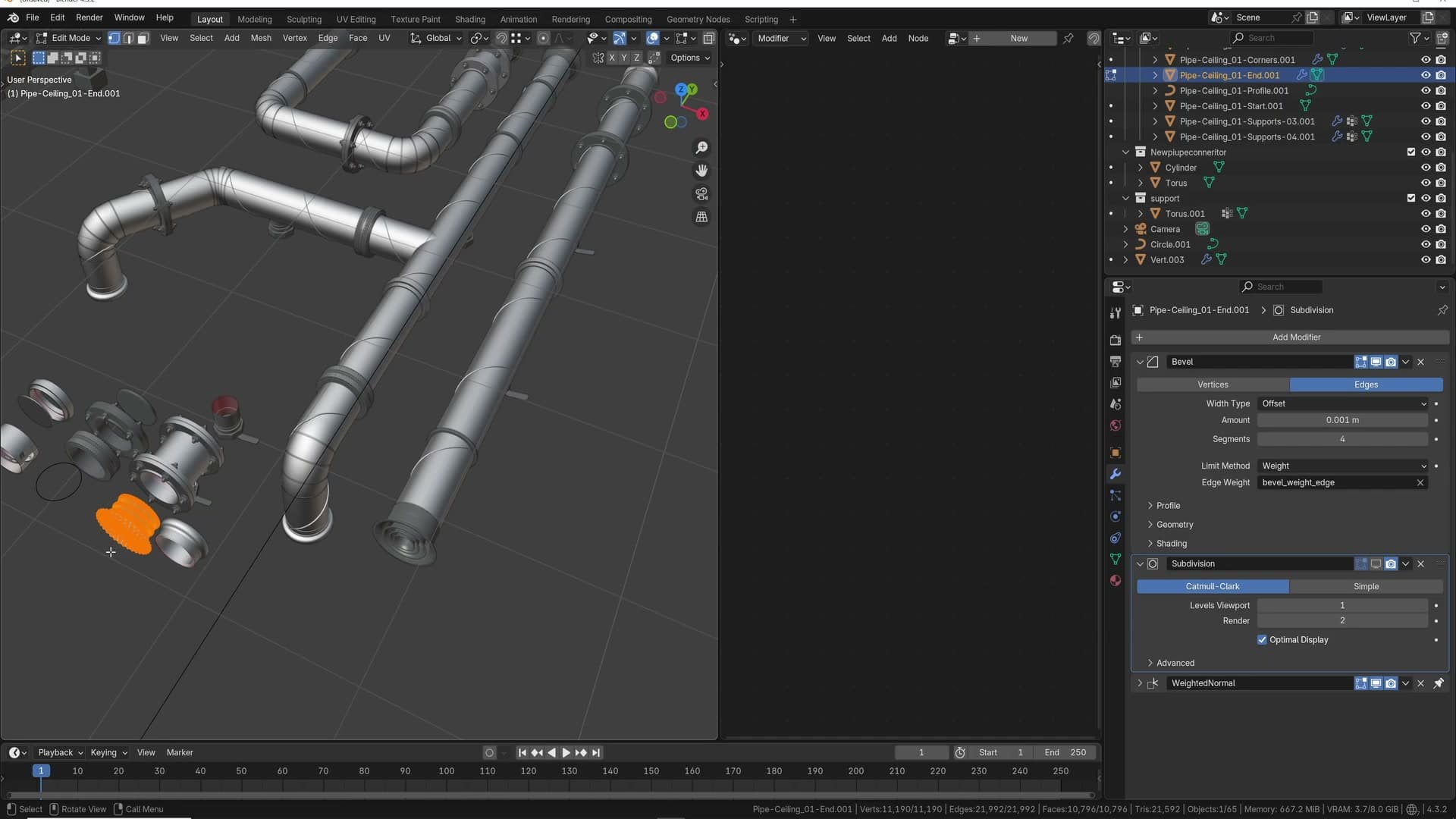
Open the Fillet Radius input on the rig and dial it in. Lower values keep the corner crisp; higher values soften it into a smoother arc. I prefer some nice roundness on most runs, so err on the side of a visible curve rather than a knife-edge. The connectors and corner parts read better against a soft bend.
After changing the fillet, revisit the connector offset from the previous step. I cycle between the two settings until both the bend and the surrounding connectors sit comfortably together. A small adjustment to one usually wants a small adjustment to the other.
Start and end caps
Each pipe has a start cap and an end cap, each with their own collection wired into the rig. Which end of the curve counts as start versus end isn't decided by how the geometry looks in the viewport. It's decided by the direction of the underlying curve, which is why the same mesh can appear flipped depending on where you slot it.
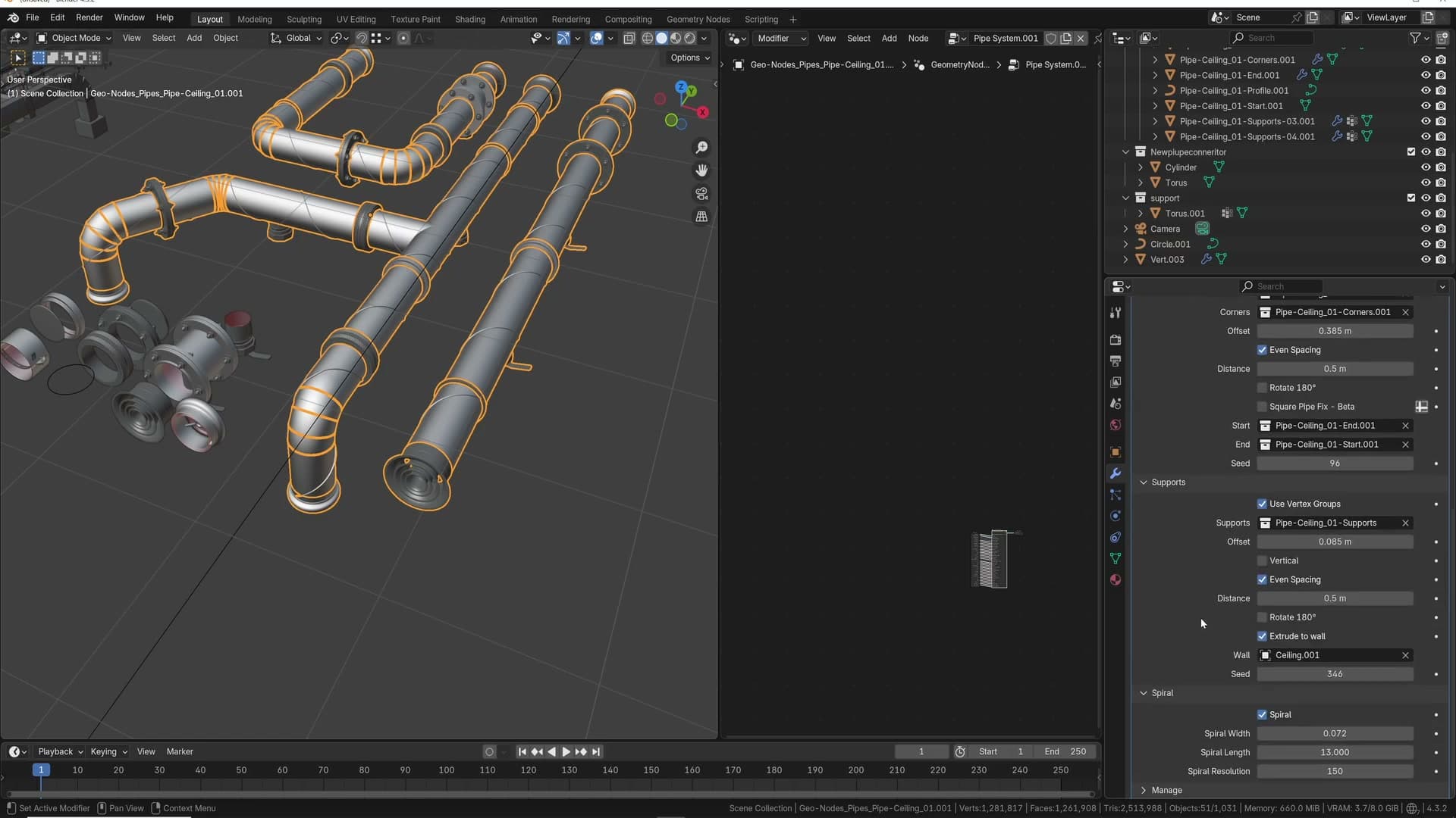
To check orientation, open the start cap object in edit mode, press A to select all of its vertices and rotate them on the Z axis. The cap on the pipe rotates with it, so you can see which way the rig thinks the start is currently facing and decide whether that matches your intent.
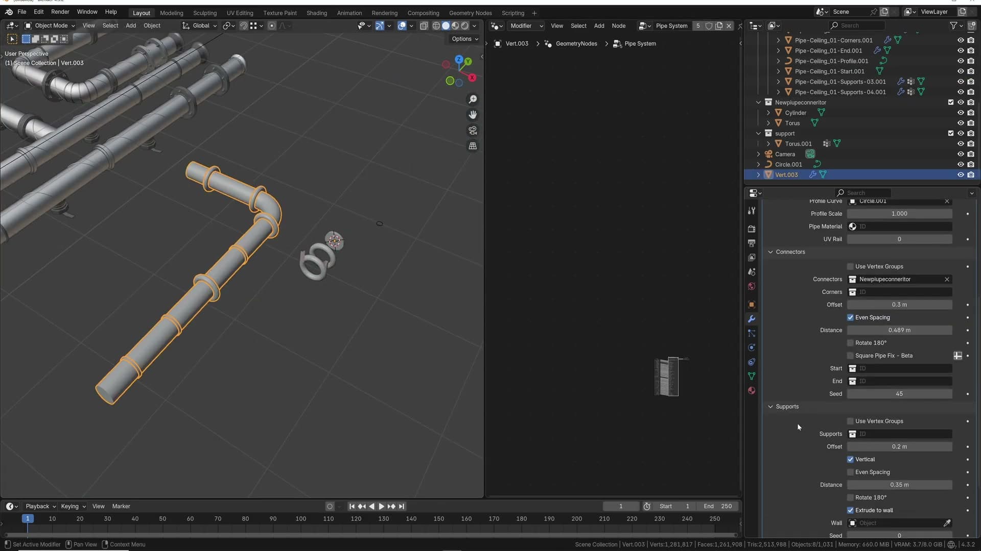
Like connectors, the cap collections randomise across whatever you put in them. The bundled pipe systems ship with two or three variants per cap so the two ends of a long run don't look identical. Adding more meshes to the start or end collection extends that variety without any further setup on the rig.
Supports and extrude-to-wall
Configuring vertical supports for ceiling pipes, controlling their offset and spacing, and snapping them onto a wall using the extrude vertex group.
Vertical vs sideways orientation
The support element ships with an orientation control, and by default it is set to vertical. That default exists because the same rig also drives other pipe systems (guttering, for example) where the supports need to run sideways into a wall rather than straight up. By telling the system which way the support is going, the rig knows where to place the bracket relative to the pipe.
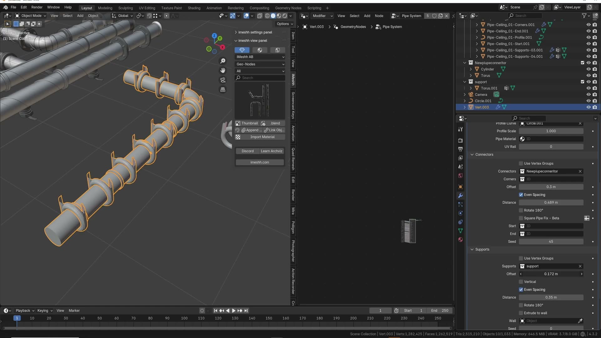
For a ceiling-mounted run the support is not going sideways into a wall. It is going up to the ceiling. Leave the orientation on vertical and each support points cleanly at the surface above the pipe, ready to anchor into it.
Support offset and even spacing
With a support placed, the next two inputs to reach for are offset and even spacing. Offset controls how far the supports sit in from the ends of the run. Increase it and the supports push further away from the end caps. That's what you want: supports generally belong along the body of the pipe rather than crowding the start and end fittings.
Enabling even spacing then distributes whatever supports remain in a predictable, regular pattern along the length of the pipe. You can also dial the number of supports up or down from there: reduce the count and the rig redistributes the survivors so they are still evenly spaced, just sparser.
Extrude-to-wall vertex group
The last support feature is extrude to wall, which lets the rig solve the support length automatically against a surface (usually a ceiling for an overhead run, or a wall for a horizontal one). The setup needs two ingredients: a target object with a flat face for the supports to land on, and a vertex group on that object so the rig knows which face is the target.
On the target object, head into the Object Data properties and add a new vertex group. The group should be called extrude, exactly that spelling. Assign the relevant face (in this case the ceiling face the pipe sits beneath) to the group.
Back on the pipe object, enable the extrude option on the support and then pick the ceiling object as the wall target in the support's input slot. Every support along the run now extends itself up to the ceiling face automatically. There is no manual measuring, no per-support placement. The rig handles the connection between the pipe and the surface for you, even on a long run with dozens of supports.
One quirk to be aware of: occasionally the supports will flip the wrong way and point at the floor instead of the ceiling. It does not happen every time, but when it does the fix is usually a small nudge to the input value. Adjust it ever so slightly and the orientation snaps back to where it should be.
T-junctions, spirals and axis flipping
The known quirks: broken T-junctions when extruding mid-curve, the spiral wrap with its resolution control, and how curve normals flip orientation across multiple axes.
Why T-junctions break
The pipe rig handles most curve shapes you throw at it, but T-junctions are the one consistent trouble spot. If you extrude a new vertex out of the middle of an existing pipe to form a side branch, you can end up with one arm of the T rendering perfectly and the other losing its connectors and supports entirely. Try the opposite branch and that one works fine. There's no obvious reason why one direction breaks and the other doesn't.
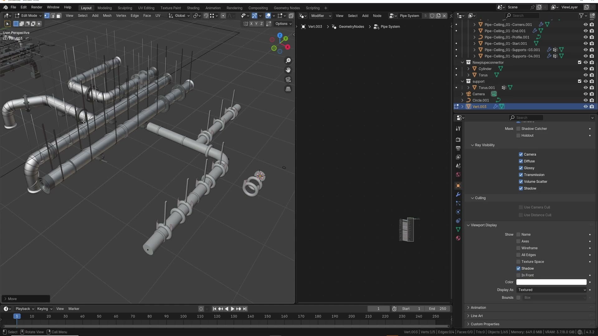
I'll be candid: something about the flow direction Blender assigns to the underlying curve is what's tripping the geometry nodes, and I'm not entirely sure which way the chain has to run for both arms to behave. Working it out from scratch took trial and error.
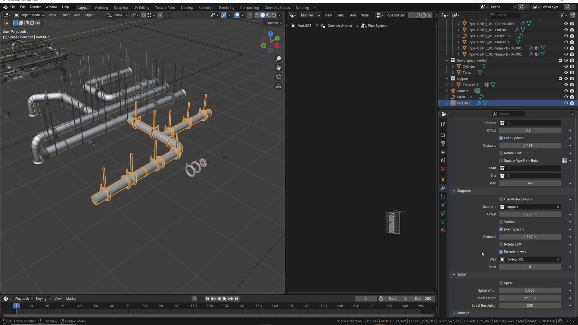
The workaround is to skip the manual approach entirely and use the pre-made T-junction template that ships with the system. Drop in the preset, then reshape its existing vertices to match your run. Even with the preset, if connectors or supports vanish on one side, drop the offset value until they reappear on that branch.
Spiral wrap and resolution
The system also includes a spiral wrap that coils around the outside of the pipe. It's the kind of ribbed detail you see on real industrial conduit and flexible ducting. It's a separate input on the geometry-nodes setup, so you can enable it on any run without rebuilding the chain.
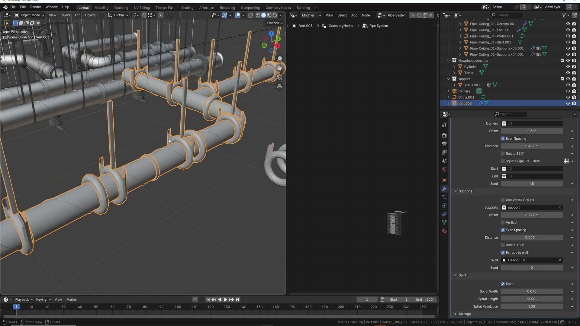
Width is the first control to reach for. A value of 0.07 is a sensible starting point for the spiral thickness; nudge it up or down depending on the gauge of pipe you're building.
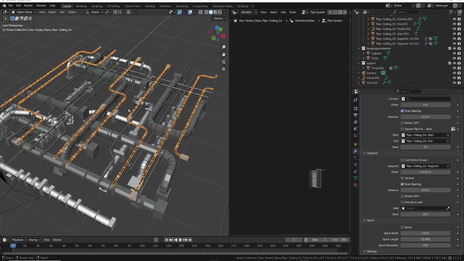
The second control is spiral resolution. This matters most on the corner pieces: if the resolution is too low, the spiral steps around the bends in jagged segments rather than following the curve smoothly. Raise it until the corners read as a continuous coil. On straight runs the default is almost always fine. It's only the corners that expose the segmentation.
Plug socket and axis flipping
Among the bundled presets is a plug-socket variant. From a ceiling-level distance you'd barely register it as a plug, but the geometry is there: the start cap is a wire disappearing into the ceiling and the end cap is the plug itself. It's the kind of detail that fits a loft apartment where exposed conduit drops down a wall to a socket someone can actually plug into.
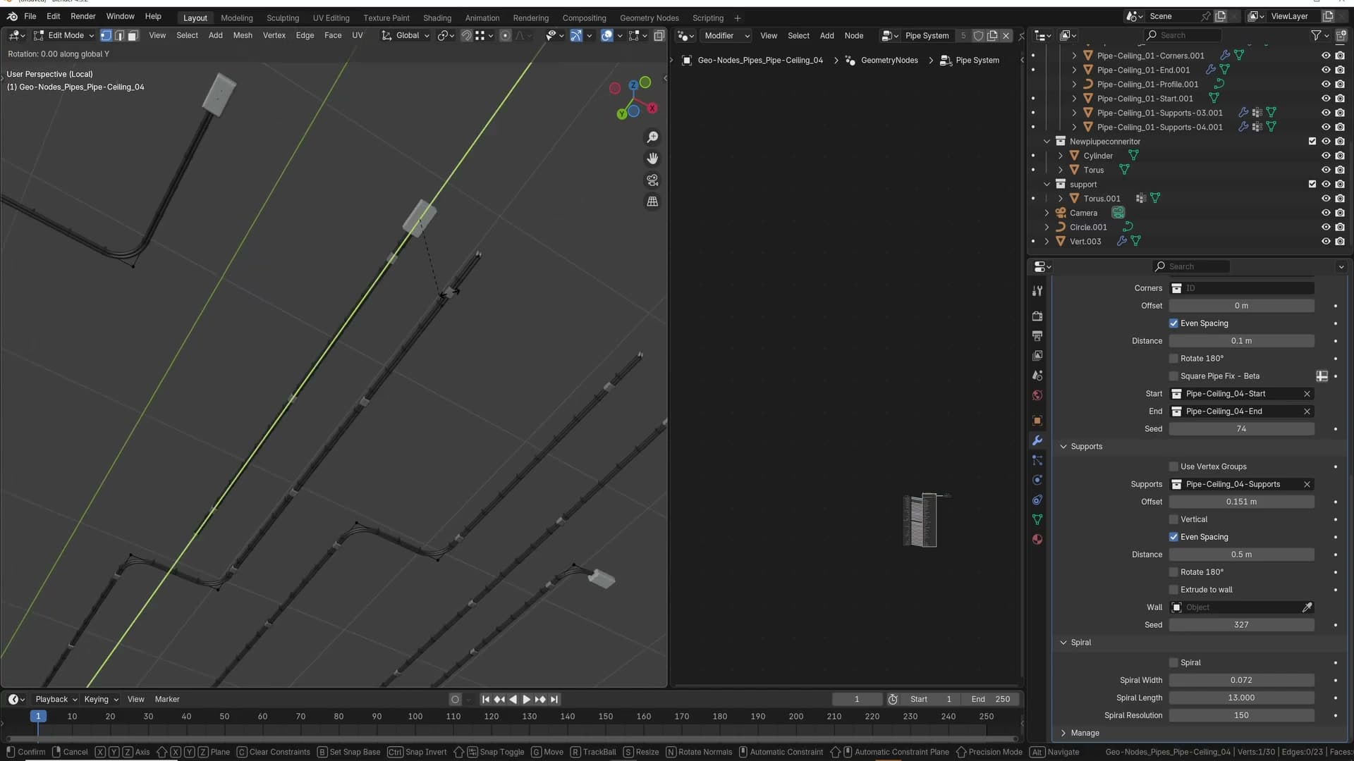
This preset is also where the axis-flipping quirk becomes obvious. Select the end vertex of the chain and extrude. Everything looks right. Select what you think is the same end on the other side and extrude that way instead, and Blender reassigns which vertex it considers the start. The whole system flips: the wire end and the plug end swap places.
The same behaviour appears whenever you extrude across more than one axis. Build a run along the ceiling, then extrude down the wall, and the corner part where the chain turns can rotate 90° from where you expect it. The geometry of the corner is correct, just oriented to the wrong axis, because Blender's curve normals reorient when the chain changes direction.
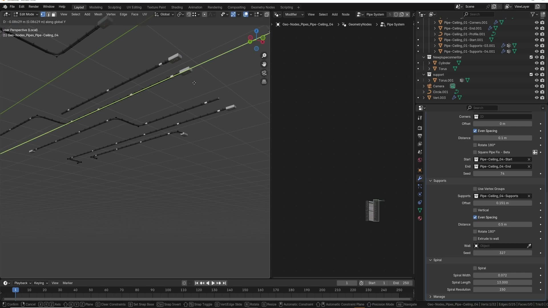
There's no clean fix inside the rig itself. There's no real way for Blender to know which way a one-dimensional edge should be facing. In practice the system still works most of the time. When it doesn't, fall back to one of the pre-made presets and reshape that rather than building the multi-axis chain from a single vertex.
The guttering preset
How the separate guttering rig behaves, the correct direction to extrude from, and the trick for keeping multiple gutter sections aligned in the same scene.
Guttering quirks and flipped supports
Guttering is the most temperamental part of the rig. To make it predictable, the add-on ships a pre-made guttering system you can drop straight into the scene rather than building one from scratch.
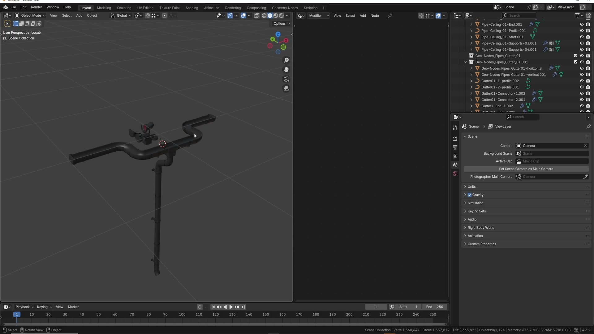
The quirk to know about: if you take an edge from the supplied guttering rig and extrude it out, some of the supports flip upside down. There's no obvious reason. Blender simply decides the curve needs to flow in the opposite direction. Delete the vertex you just created and the supports snap back to the correct orientation, which confirms that the new geometry is what's confusing the rig rather than the preset itself.
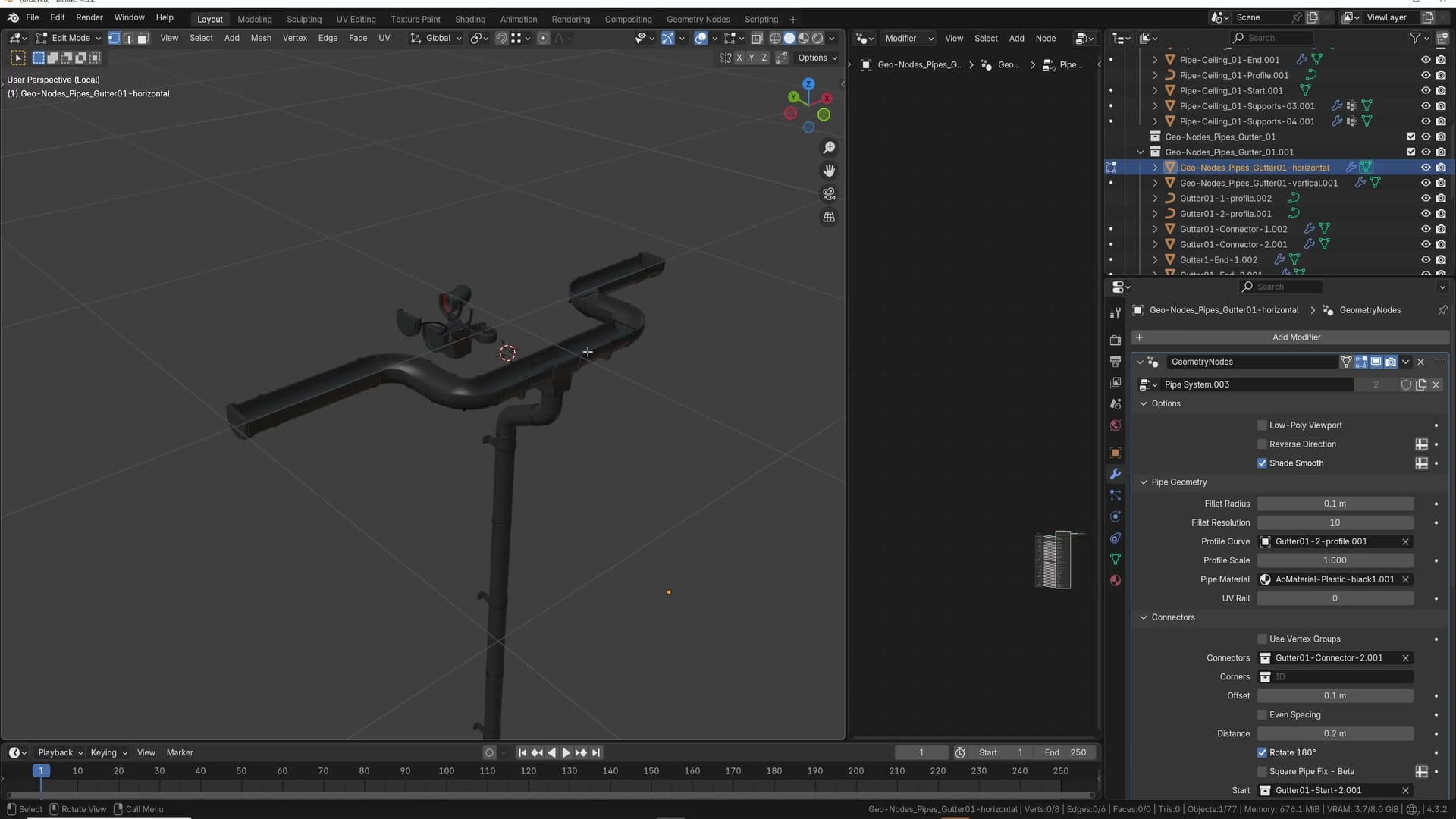
The takeaway is to treat the preset as a starting point that already has its flow direction sorted. Build outward from the correct end (covered in the next sub-lesson) and you avoid the flipping behaviour entirely.
Extrude in the direction of flow
The pipe system has an internal sense of which way it considers "flow" along the guttering rig. Extrude in that direction and the supports stay oriented correctly; extrude from the opposite end and you get the flipped-support behaviour from the previous sub-lesson.
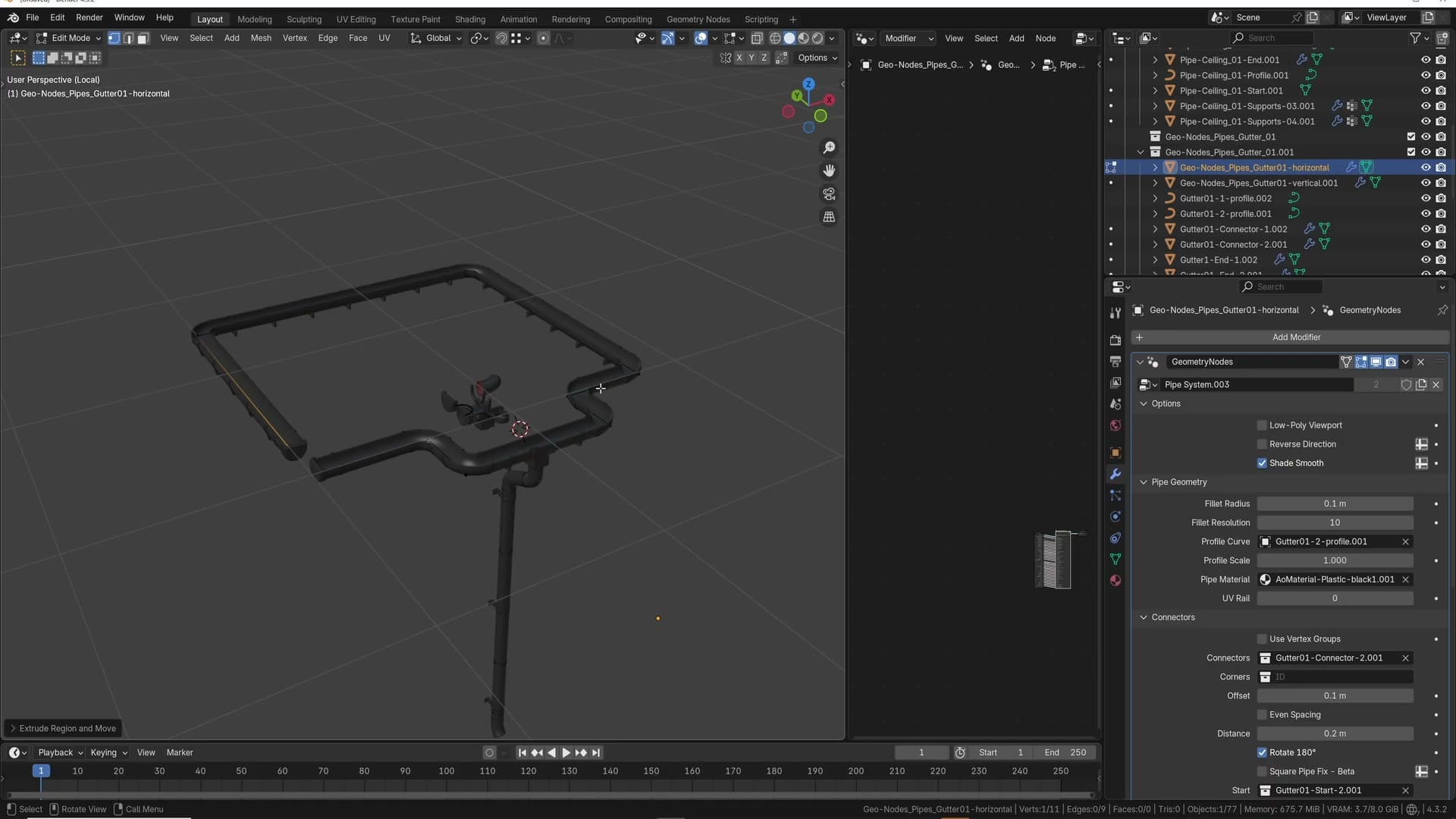
Select the edge on the flow-correct side and extrude outward along that axis. If some of the supports still look wrong, nudge the new vertex slightly along the X axis. The bug is length-sensitive, and a small offset is often enough to settle the rig. Once that first leg is behaving, you can extrude again on the Y axis to turn the corner and keep going.
That's how you wrap guttering around a full building: each new extrusion follows on from the last, and because you started from the correct end every leg inherits the right orientation. Toggling low-poly mode while you work keeps the viewport responsive; flip it back off to see the supports at full detail.
The general rule is simple: use the supplied preset, remember which side is the extrude-from side, and only build outward from there. Extruding from the start side is where the problems begin.
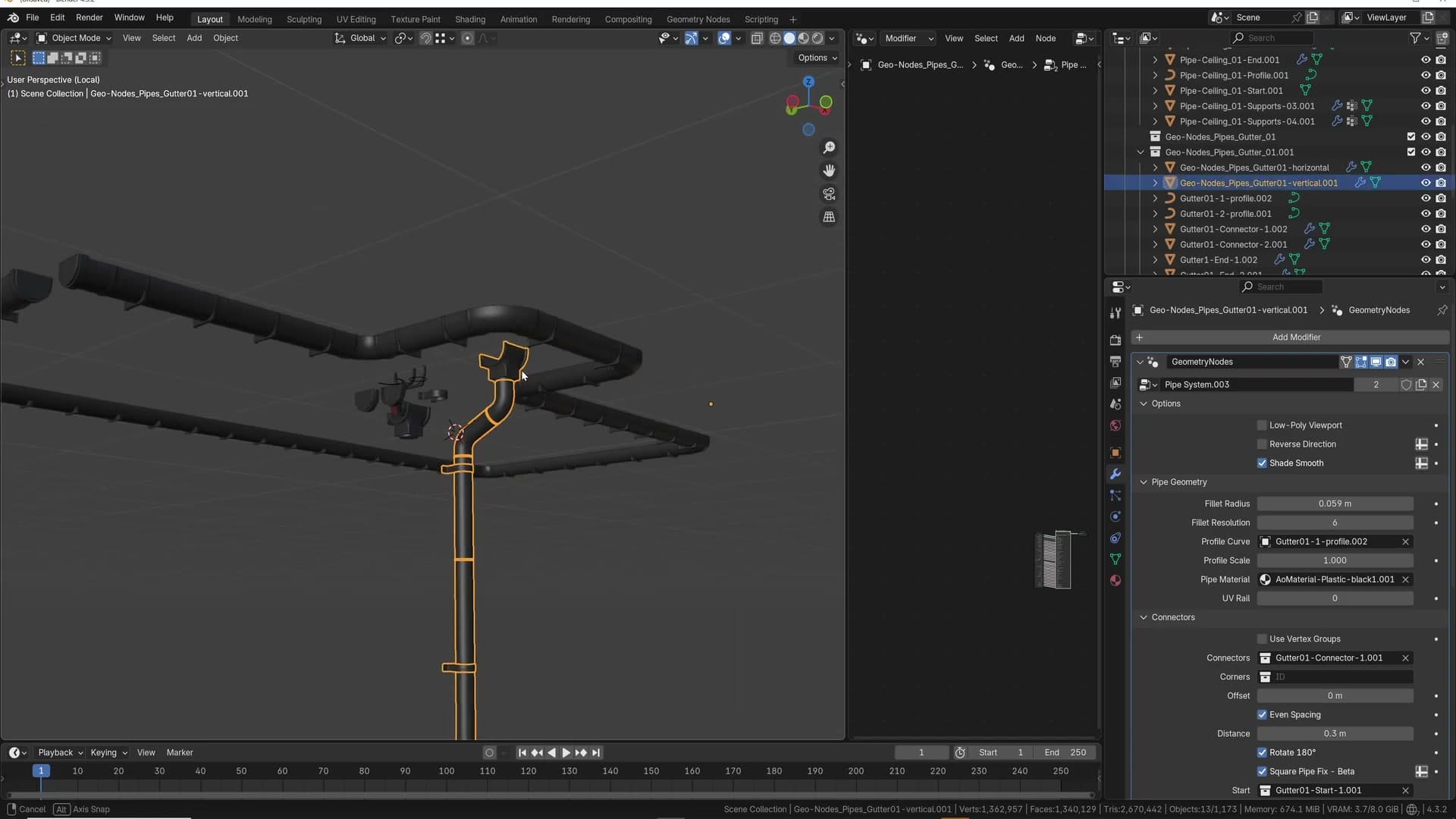
Aligning independent gutter sections
Each guttering rig in the scene is independent. It has its own supports and its own connector geometry, which is what lets the system stay flexible, but it also means two separate runs won't automatically line up to the same height when you place them in the same scene.
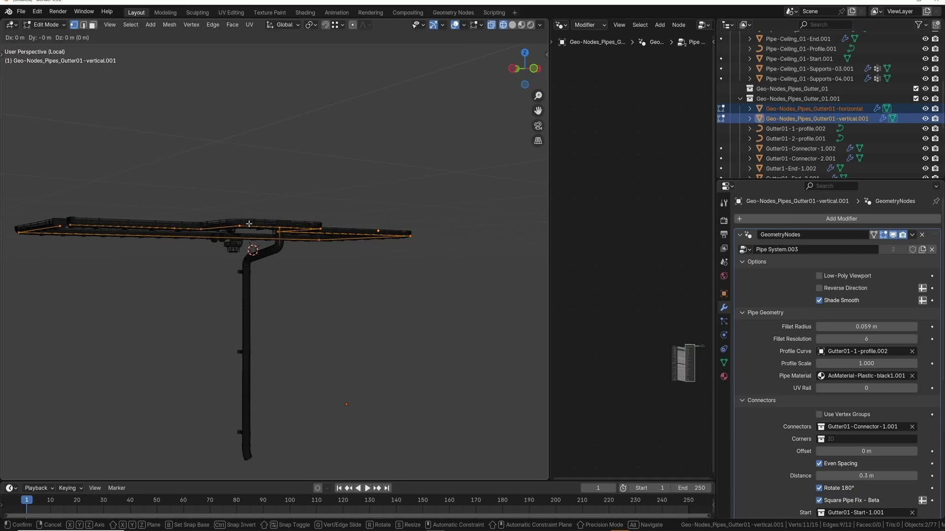
To match them up, drop the second run roughly where you want it (for example pulled out on the Y axis), then select both objects and tab into edit mode together. Select all the vertices you want aligned, then press G, Z, . , 1 and the matching vertices snap to the same height in one move.
From there the two runs read as one continuous piece of guttering, even though under the hood they remain two independent rigs with their own modifier inputs.
Performance, VRAM and what's next
Why the instanced rig keeps VRAM use low even on dense ceiling runs, where the system goes next, and how iMeshh subscribers can get support when they hit one of the quirks.
Instancing keeps VRAM tiny
The detail you see across a finished run isn't being duplicated under the hood. Each connector, support and corner part exists as a single source mesh, and the geometry-nodes rig instances it everywhere the curve calls for one. That's why a dense ceiling run with hundreds of fittings still leaves the VRAM counter almost untouched. You're paying for one of each, not one per placement.
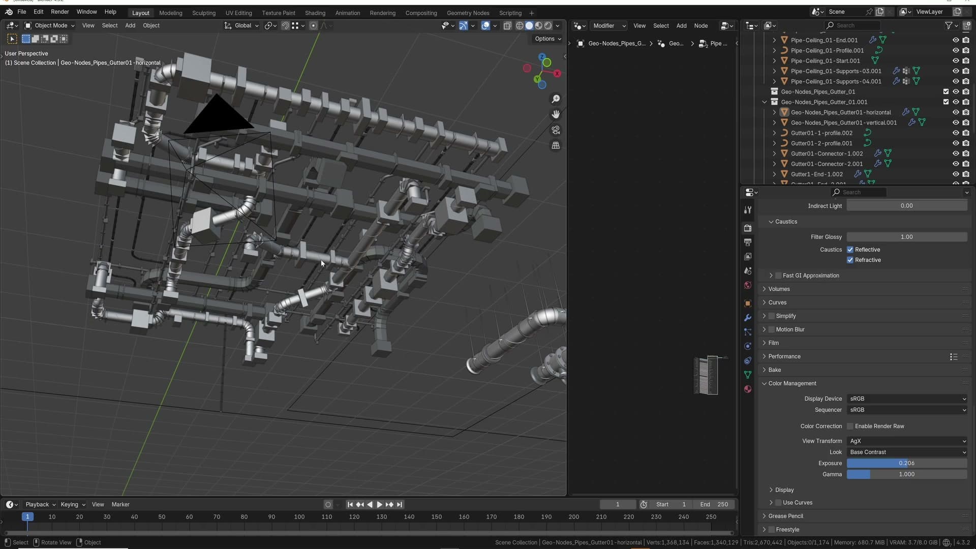
The practical upside is that you can lean on high-detail parts without thinking about cost. Guttering and pipework are the kind of thing that gets cut for time on archviz jobs. Sometimes you end up dropping in a plain cylinder just to get the shot out the door. Having a system that produces proper detail at instance-level cost means there's no longer a trade-off between schedule and finish.
Version two and getting support
The rig isn't finished. A version two is on the cards with the original geometry-nodes author, and the priority is the rough edges covered earlier in the post: the curve-orientation flipping that rotates corner parts and the T-junctions that don't always distribute supports cleanly. Until then, the bundled templates exist precisely so you don't have to fight those cases. When you need a T-junction or a multi-axis run, grab the preset and reshape it rather than rolling one from scratch.
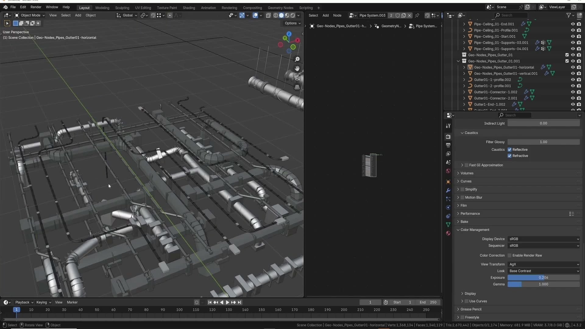
If you do hit a problem with the system and you're an iMeshh subscriber, get in touch through the usual support channels and the team will work through it with you. The further you stray from a simple in-plane run (branching on multiple axes, mixing several systems, unusual angles), the more chance you'll meet one of the quirks that version two is targeting, so it's worth flagging anything reproducible.
What you're left with most of the time, though, is a high-detail pipe run that drops into a render and looks the part without manual modelling time. If you want a deeper walkthrough of how the underlying node graph is put together, leave a comment on the video. There's room for a follow-up that opens up the rig itself. Thanks for watching.
Tools and credits
Everything mentioned in this tutorial, with links.
- Blender: the renderer this entire build runs in.
- iMeshh: studio platform (project management, client review, asset library, invoicing). The asset library used in this tutorial is included with every iMeshh Pro plan.
- Poly Haven: free CC0 textures and HDRIs.
Pillar guide: Imeshh Tools hub